Tripp Lite VGA over Cat5 Extenders/Splitters 9 Owner's manual
- Category
- AV extenders
- Type
- Owner's manual

1
Owner’s Manual
VGA Over Cat5 Extenders
and Extender/Splitters
Extender Kit Models: B130-101-2, B130-101A-2,
B130-101-WP-1, B130-101A-WP-2, B130-101S-2,
B130-111, B130-111A and B130-101-U
Transmitter Unit Models: B132-002-2,
B132-002A-2, B132-004-2, B132-004A-2 and
B132-008A-2
Receiver Unit and Remote Repeater Models:
B132-100-1, B132-100A, B132-100-WP-1,
B132-100A-WP-1, B132-110 and B132-110A
1111 W. 35th Street, Chicago, IL 60609 USA • www.tripplite.com/support
Copyright © 2015 Tripp Lite. All rights reserved.
All trademarks are the sole property of their respective owners.
PROTECT YOUR INVESTMENT!
Register your product for quicker service
and ultimate peace of mind.
You could also win an ISOBAR6ULTRA
surge protector—a $100 value!
www.tripplite.com/warranty
15-08-104-933289-EN.indd 1 8/21/2015 3:45:46 PM

2
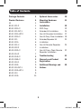
Table of Contents
Package Contents 3
Product Features 4
All 4
B130-101-2 4
B130-101A-2 4
B130-101-WP-1 4
B130-101A-WP-2 5
B130-101S-2 5
B130-111 5
B130-111A 6
B130-101-U 6
B132-002-2 7
B132-002A-2 7
B132-004-2 7
B132-004A-2 8
B132-008A-2 8
B132-100-1 9
B132-100A 9
B132-100-WP-1 9
B132-100A-WP-1 9
B132-110 9
B132-110A 10
Optional Accessories 10
Mounting Hardware 11
Instructions
Installation 12
EDID Copy 12
Extender Kit Installation 14
Non-Kit Standard Installation 17
Non-Kit Daisy Chain Installation 19
Extender/Repeater Kit 21
Installation
Non-Kit Remote Repeater 24
Installation
Non-Kit Daisy Chain Remote 27
Repeater Installation
Troubleshooting 31
Warranty and Product 34
Registration
Additional Warnings and 35
Notices
15-08-104-933289-EN.indd 2 8/21/2015 3:45:46 PM

3
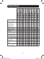
Package Contents
B130-101-2
B130-101A-2
B130-101-WP-1
B130-101A-WP-2
B130-101S-2
B130-111
B130-111A
B130-101-U
B132-002-2
B132-002A-2
B132-004-2
B132-004A-2
B132-008A-2
B132-100-1
B132-100A
B132-100-WP-1
B132-100A-WP-1
B132-110
B132-110A
Local Unit (L), Remote
Unit (R) or Both (B)
B B B B B B B B L L L L L R R R R R R
1 or 2 External
Power Supplies
(Input: 100-240 V,
50/60 Hz, 0.5 A
Output: 5 V, 2 A)
2 2 2 2 2 2 2 0 1 1 1 1 1 1 1 1 1 1 1
Mounting Hardware X X X X X X X X X X X X X X
Wallplate Screws X X X X
Screwdriver X X X X X X X X X X X X X X
3.5 mm Male to DB9
Male Adapter Cable
X
3.5 mm Male to DB9
Female Adapter Cable
X
1 ft. VGA Splitter Cable X
1 ft. VGA + Audio
Splitter Cable
X
1 ft. VGA Daisy Chain
Cable
X
1 ft. VGA + Audio
Daisy Chain Cable
X X
15-08-104-933289-EN.indd 3 8/21/2015 3:45:46 PM

4
Product Features
All
• Support a maximum resolution of 1920 x 1440 @ 60 Hz.
• All operating systems supported.
• Plug and play; no software or drivers required.
• HDCP compliant.
B130-101-2
• Extends a VGA video signal (1024 x 768 @ 60 Hz) up to 1,000 ft. from
the source.
• Features an additional VGA port, allowing for the connection of a local
monitor.
• Includes mounting hardware that allows units to be wall-mounted, rack
mounted or pole mounted.
• Features built-in equalization and gain controls to adjust the video image.
• EDID copy feature ensures optimal display compatibility.
B130-101A-2
• Extends both a VGA video (1024 x 768 @ 60 Hz) and an audio signal
up to 1,000 ft. from the source.
• Features additional VGA and 3.5 mm ports, allowing for the connection
of a local monitor and speakers.
• Includes mounting hardware that allows units to be wall-mounted, rack
mounted or pole mounted.
• Features built-in equalization and gain controls to adjust the video image.
• EDID copy feature ensures optimal display compatibility.
B130-101-WP-1
• Extends a VGA video signal (1024 x 768 @ 60 Hz) up to 1,000 ft. from
the source.
• Includes a VGA splitter cable, which allows for the connection of a local
monitor.
• Includes RJ45 jacks, allowing for easy connection via standard patch
cables; no 110 punchdown connections required.
• Features built-in equalization and gain controls to adjust the video image.
15-08-104-933289-EN.indd 4 8/21/2015 3:45:46 PM

5
B130-101A-WP-2
• Extends both a VGA video (1024 x 768 @ 60 Hz) and an audio signal
up to 1,000 ft. from the source.
• Includes a VGA + audio splitter cable, which allows for the connection
of a local monitor and speakers.
• Includes RJ45 jacks, allowing for easy connection via standard patch
cables; no 110 punchdown connections required.
• Features built-in equalization and gain controls to adjust the video image.
• EDID copy feature ensures optimal display compatibility.
B130-101S-2
• Extends both a VGA video (1024 x 768 @ 60 Hz) and RS-232 Serial
signal up to 1,000 ft. from the source.
• Includes mounting hardware that allows units to be wall-mounted, rack
mounted or pole mounted.
• Features built-in equalization and gain controls to adjust the video image.
• EDID copy feature ensures optimal display compatibility.
B130-111
• Kit comes with both local transmitter and remote repeater units.
• Locate multiple monitors at different points in a chain of up to 2,000 ft.
by connecting an additional remote receiver unit (B132-100-1 or
B132-100-WP-1), or a remote repeater unit (B132-110).
• Up to 4 remote units (3 remote repeaters and 1 receiver) can be
connected together, providing video to up to 4 remote displays in a full chain.
• Extends a 1024 x 768 (60 Hz) signal up to 1,000 ft. between the local
transmitter and the first remote repeater unit in the installation.
• Extends a 1024 x 768 (60 Hz) signal up to an additional 1,000 ft. from
the first remote repeater unit to the last display in the installation, for a
maximum extension distance of 2,000 ft.
• Local unit includes an additional VGA port, allowing for the connection
of a local monitor.
• Features built-in equalization and gain controls to adjust the video image.
• Includes mounting hardware that allows units to be wall-mounted,
rack mounted or pole mounted.
Product Features continued
15-08-104-933289-EN.indd 5 8/21/2015 3:45:46 PM

6
Product Features continued
B130-111A
• Kit comes with both local transmitter and remote repeater units.
• Locate multiple monitors/speakers at different points in a chain of up to
2,000 ft. by connecting an additional remote receiver unit (B132-100A
or B132-100A-WP-1), or a remote repeater unit (B132-110A).
• Up to 4 remote units (3 remote repeaters and 1 receiver) can be
connected together, providing audio/video to up to 4 remote displays/
speakers in a full chain.
• Extends a 1024 x 768 (60 Hz) video and audio signal up to 1,000 ft.
between the local transmitter and the first remote repeater unit in the
installation.
• Extends a 1024 x 768 (60 Hz) video and audio signal up to an
additional 1,000 ft. from the first remote repeater unit to the last set
of display and speakers in the installation, for a maximum extension
distance of 2,000 ft.
• Local unit includes additional VGA video and 3.5 mm audio ports,
allowing for the connection of a local monitor and speakers.
• Features built-in equalization and gain controls to adjust the video image.
• Includes mounting hardware that allows units to be wall-mounted,
rack mounted or pole mounted.
B130-101-U
• Extends a VGA video signal (1024 x 768 @ 60 Hz) up to 500 ft. from
the source.
• Power is supplied by the USB connection on the local transmitter unit;
no external power supplies are required.
• Dongle-style local and remote units come with built-in VGA connectors;
no external VGA cables are required.
• Features built-in equalization and gain controls to adjust the video image.
15-08-104-933289-EN.indd 6 8/21/2015 3:45:46 PM

7
Product Features continued
B132-002-2
• Works with the B132-100-1 and B132-100-WP-1 remote units to extend a
VGA video signal (1024 x 768 @ 60 Hz) up to 1,000 ft. from the source.
• Able to transmit a single VGA video signal to 2 monitors.
• Includes mounting hardware that allows unit to be wall-mounted, rack
mounted or pole mounted.
• EDID copy feature ensures optimal display compatibility.
B132-002A-2
• Works with the B132-100A and B132-100A-WP-1 remote units to
extend both a VGA video (1024 x 768 @ 60 Hz) and an audio signal up
to 1,000 ft. from the source.
• Transmits a single VGA video and audio signal to 2 sets of monitors and
speakers.
• Includes mounting hardware that allows unit to be wall-mounted, rack
mounted or pole mounted.
• EDID copy feature ensures optimal display compatibility.
B132-004-2
• Features an additional VGA port, allowing for the connection of a local
monitor.
• Works with the B132-100-1 and B132-100-WP-1 remote units to extend a
VGA video signal (1024 x 768 @ 60 Hz) up to 1,000 ft. from the source.
• Able to transmit up to 5 (4 remote, 1 local) VGA video signals.
• Expand the number of connected monitors to up to 25 (24 remote,
1 local) by daisy chaining up to 6 local units together.
Note: B132-002-2 local units cannot be daisy chained.
• Includes mounting hardware that allows unit to be wall-mounted, rack
mounted or pole mounted.
• EDID copy feature ensures optimal display compatibility.
• Up to three local units can be connected to a Tripp Lite B132-004-RB
rackmount bracket and mounted in just 1U of rack space.
15-08-104-933289-EN.indd 7 8/21/2015 3:45:46 PM

8
Product Features continued
B132-004A-2
• Works with the B132-100A and B132-100A-WP-1 remote units to
extend both a VGA video (1024 x 768 @ 60 Hz) and an audio signal up
to 1,000 ft. from the source.
• Features additional VGA and 3.5 mm ports, allowing for the connection
of a local monitor and speakers.
• Transmits a single VGA video and audio signal to up to 5 sets
(4 remote, 1 local) of monitors and speakers.
• Expand the number of connected monitors/speakers to up to 25
(24 remote, 1 local) by daisy chaining up to 6 local units together.
Note: B132-002A-2 local units cannot be daisy chained.
• Includes mounting hardware that allows unit to be wall-mounted, rack
mounted or pole mounted.
• Up to three local units can be connected to a Tripp Lite B132-004-RB
rackmount bracket and mounted in just 1U of rack space.
• EDID copy feature ensures optimal display compatibility.
B132-008A-2
• Works with the B132-100A and B132-100A-WP-1 remote units to extend
both a VGA video (1024 x 768 @ 60 Hz) and an audio signal up to 1,000
ft. from the source.
• Features additional VGA and 3.5 mm ports, allowing for the connection of a
local monitor and speakers.
• Transmits a single VGA video and audio signal to up to 9 sets (8 remote, 1
local) of monitors and speakers.
• Expand the number of connected monitors/speakers to up to 49 (48
remote, 1 local) by daisy chaining up to 6 local units together.
Note: B132-002A-2 local units cannot be daisy chained.
• Includes mounting hardware that allows unit to be wall-mounted, rack
mounted or pole mounted.
• EDID copy feature ensures optimal display compatibility.
15-08-104-933289-EN.indd 8 8/21/2015 3:45:46 PM

9
Product Features continued
B132-100-1
• Includes mounting hardware that allows unit to be wall-mounted, rack
mounted or pole mounted.
• Features built-in equalization and gain controls to adjust the video image.
B132-100A
• Includes mounting hardware that allows unit to be wall-mounted, rack
mounted or pole mounted.
• Features built-in equalization and gain controls to adjust the video image.
B132-100-WP-1
• Includes RJ45 jacks, allowing for easy connection via standard patch
cables; no 110 punchdown connections required.
• Features built-in equalization and gain controls to adjust the video image.
B132-100A-WP-1
• Includes RJ45 jacks, allowing for easy connection via standard patch
cables; no 110 punchdown connections required.
• Features built-in equalization and gain controls to adjust the video image.
B132-110
• Extends and expands your Tripp Lite VGA over Cat5 installation, allowing
you to locate multiple monitors at different points in a chain of up to
2,000 ft.
• Up to 4 remote units (3 remote repeaters and 1 receiver) can be connected
together, providing video to up to 4 remote displays in a full chain.
• Extends a 1024 x 768 (60 Hz) signal up to 1,000 ft. between the local
transmitter and the first remote repeater unit in the installation.
• Extends a 1024 x 768 (60 Hz) signal up to an additional 1,000 ft. from
the first remote repeater unit to the last display in the installation, for a
maximum extension distance of 2,000 ft.
• Features built-in equalization and gain controls to adjust the video image.
• Includes mounting hardware that allows unit to be wall-mounted, rack
mounted or pole mounted.
15-08-104-933289-EN.indd 9 8/21/2015 3:45:46 PM

10
Optional Accessories
• B132-004-RB 1U Rackmount Bracket
• N001-Series Cat5e Snagless Patch Cables
• N002-Series Cat5e Patch Cables
• N020-01K-GY Gray Cat5e Bulk Stranded Cable – 1,000 ft.
• N022-01K-GY Gray Cat5e Bulk 24 AWG Solid Cable – 1,000 ft.
• N030-010 10-pack of RJ45 Plugs for Solid-wire Cat5e Cable
• N031-050 50-pack of RJ45 Plugs for Stranded-wire Cat5e Cable
• N201-Series Cat6 Snagless Patch Cables
• N202-Series Cat6 Snagless 24 AWG Solid Patch Cables
• N222-01K-GY Gray Cat6 Bulk 24 AWG Solid Cable – 1,000 ft.
• P312-Series Audio Cables
Product Features continued
B132-110A
• Both extends and expands your Tripp Lite VGA + audio over Cat5
installation, allowing you to locate multiple monitors/speakers at
different points in a chain of up to 2,000 ft.
• Up to 4 remote units (3 remote repeaters and 1 receiver) can be
connected together, providing audio/video to up to 4 remote displays/
speakers in a full chain.
• Extends a 1024 x 768 (60 Hz) video and audio signal up to 1,000 ft.
between the local transmitter and the first remote repeater unit in the
installation.
• Extends a 1024 x 768 (60 Hz) video and audio signal up to an
additional 1,000 ft. from the first remote repeater unit to the last set
of display and speakers in the installation, for a maximum extension
distance of 2,000 ft.
• Features built-in equalization and gain controls to adjust the video image.
• Includes mounting hardware that allows unit to be wall-mounted, rack
mounted or pole mounted.
15-08-104-933289-EN.indd 10 8/21/2015 3:45:46 PM

11
Optional Accessories continued
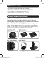
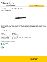
Mounting Hardware Instructions
All of the non-wallplate VGA extender products come with mounting
hardware that allows them to be mounted in a variety of ways. The
following images show the different ways the included mounting brackets
can be attached for different mounting methods.
Note: The images below show a B140-101X DVI Extender, but mounting is the
same for the VGA Extenders. The B132-004-2 and B132-004A-2 can also be
mounted to a Tripp Lite B132-004-RB 1U rackmount bracket. Up to 3 B132-004-2
or B132-004A-2 local units can be connected to a B132-004-RB.
Wall-Mount 1 Wall-Mount 2
19” Rack Mount Pole Mount
• P502-Series VGA Monitor Cables with RGB Coax
• P504-Series VGA Monitor + Audio Cables with RGB Coax
• P520-006 RS-232 Serial Extension Cable – 6 ft.
• P524-01K Zero-Skew UTP Bulk Cable – 1,000 ft.
15-08-104-933289-EN.indd 11 8/21/2015 3:45:48 PM

12
Installation
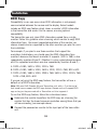
EDID Copy
Compatibility issues can occur when EDID information is not properly
communicated between the source and the display. Select models
include an EDID copy feature which stores a monitor’s EDID information
in the transmitter and sends it to the source, ensuring optimal
compatibility.
The transmitter can only store EDID information copied from a single
monitor. Follow this guideline when choosing which monitor to copy EDID
information from: the lowest supported resolution of the monitor you
choose should also be supported by the other monitors you plan to use in
the installation.
For example, if you plan to use three monitors that support the
resolutions listed below, you should copy the EDID information from
monitor A because the lowest resolution it supports (1024 x 768) is also
supported by monitors B and C. (Monitor A is also a good choice because
all of its supported resolutions are also supported by monitors B and C.)
A. 1920 x 1080, 1600 x 1200, 1024 x 768
B. 1920 x 1080, 1680 x 1050, 1600 x 1200, 1024 x 768, 800 x 600
C. 1920 x 1080, 1680 x 1050, 1280 x 768, 1600 x 1200, 1152 x 768,
1024 x 768, 800 x 600
If you are not using the EDID copy feature, the transmitter will use a
default set of EDID information.
Note: VGA over Cat5 Extender Kits and Transmitter units with a -2 at the end of
their model name support the EDID copy feature. Remote units will support EDID
copy as long as they are used with a Transmitter unit that supports it.
To use the EDID copy feature, follow the instructions below:
1
Determine the monitor to perform the EDID copy on, choosing the
monitor that has the lowest common resolution among those that you
will be connecting (see example above).
2
Connect the powered-on monitor to the input port of the transmitter
unit.
15-08-104-933289-EN.indd 12 8/21/2015 3:45:48 PM

13
3
Connect the external power supply to the transmitter unit and plug
it into a Tripp Lite Surge Protector, Power Distribution Unit (PDU) or
Uninterruptible Power Supply (UPS).
4
Wait 10 seconds for the EDID information to be copied, and then
disconnect the monitor from the transmitter unit’s input port and
proceed per the installation instructions in this manual.
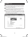
5
You can verify that the EDID information was copied via the Display
Settings screen in your computer. If the model name of the monitor
that you copied is shown in the Display field of the screen, the EDID
information has been copied successfully.
Installation continued
15-08-104-933289-EN.indd 13 8/21/2015 3:45:49 PM

14
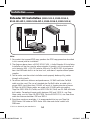
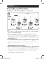
Extender Kit Installation (B130-101-2, B130-101A-2,
B130-101-WP-1, B130-101A-WP-1, B130-101S-2, B130-101-U)
Note:
1. For models that support EDID copy, perform the EDID copy procedure described
in this manual prior to installation.
2. The diagram above shows a B130-101A-2 VGA + Audio Extender Kit installation.
Installation will be the same for other extender kit models, with the exception of
units featuring VGA + RS-232 serial or VGA only. The B130-101-U gets power
from the USB cable built-in to the local unit, and doesn’t require external power
supplies.
3. Test to make sure the entire installation works properly before pulling cables
through ceilings/walls.
4. To achieve maximum distance and performance, 24 AWG solid-wire Cat5e/6
cable must be used. The use of stranded wire Cat5e/6 cable, or cable with a
gauge (AWG) size higher than 24 AWG, will result in shorter extension distance.
All Tripp Lite N202-Series cables are made with 24 AWG solid-wire cabling.
Tripp Lite N022-01K-GY (Cat5e) and N222-01K-GY (Cat6) are 24 AWG solid-wire
bulk cables. For optimal image quality between 500 and 1,000 ft., use Zero-
Skew cable, such as Tripp Lite P524-01K. For the B130-101-U, use Zero-Skew
cable for distances between 250 and 500 ft.
5. To achieve maximum resolution, it is recommended that you use Tripp Lite
P502-Series VGA video or P504-Series VGA video and audio* cables with
RGB coax.
Installation continued
*If this is a feature of your extender kit.
Transmitter Unit
Receiver Unit
15-08-104-933289-EN.indd 14 8/21/2015 3:45:49 PM

15
Installation continued
1
Make sure that the VGA, audio* and RS-232 serial* source is
powered off.
2
(B130-101-2, B130-101A-2 and B130-101S-2 only) – Connect
the VGA and audio* source to the INPUT port(s) on the transmitter
unit using a VGA and audio* cable.
3
(B130-101S-2 only) – Connect the included 3.5 mm Male to DB9
Female adapter cable to the 3.5 mm INPUT port on the transmitter
unit, and then connect the computer to the adapter using a DB9 cable.
4
(B130-101-U only) – Connect the built-in VGA and USB connectors
on the transmitter unit to the source computer.
5
(B130-101-WP-1 and B130-101A-WP-2 only) – If you wish to
connect a local monitor and speakers*, connect the male end of the
included splitter cable to the INPUT port(s) on the transmitter unit,
and then connect one of the female ends of the splitter cable to
the source using VGA and audio* cable. If you are not connecting a
local monitor and speakers*, the source can be connected directly to
the INPUT port(s) on the transmitter unit without using the included
splitter cable.
6
(Optional) – Connect a local monitor and speakers* to the LOCAL
port(s) on the transmitter unit, or the remaining female connector(s)
on your splitter cable*, using a VGA and audio* cable.
Note: The B130-101S-2 comes with a local video port only, and does not
contain a local RS-232 Serial port.
7
Connect the external power supply to the transmitter unit, and then
plug it into a Tripp Lite Surge Protector, Power Distribution Unit (PDU)
or Uninterruptible Power Supply (UPS). The B130-101-U gets power
from the USB cable built-in to the transmitter unit and doesn’t require
external power supplies.
8
Using Cat5e/6 cable, connect the RJ45 OUTPUT port on the
transmitter unit to the RJ45 INPUT port on the receiver unit.
9
(B130-101-U only) – Connect the built-in VGA connector on the
receiver unit to the VGA port on a monitor.
*If this is a feature of your extender kit.
15-08-104-933289-EN.indd 15 8/21/2015 3:45:49 PM

16
Installation continued
10
Connect a monitor and speakers* to the OUTPUT ports on the
receiver unit using a VGA and audio* cable.
11
(B130-101S-2 only) – Connect the included 3.5 mm Male to DB9
Male adapter cable to the 3.5 mm OUTPUT port on the receiver unit,
and then connect the serial device to the adapter using a DB9 cable.
12
Connect the external power supply to the receiver unit, and then plug
it into a Tripp Lite Surge Protector, Power Distribution Unit (PDU) or
Uninterruptible Power Supply (UPS). The B130-101-U gets power
from the USB cable built-in to the transmitter unit and doesn’t require
external power supplies.
13
Turn on the power to the monitor, speakers* and RS-232 serial
device.*
14
Turn on the power to the monitor, audio* and RS-232 serial* source.
15
If necessary, adjust the equalization and gain controls using the
included screwdriver to improve the video image.
Note: The B130-101-U receiver unit contains a switch that changes the upper
and lower limits of the Gain adjustment control depending on the length of your
installation. If using 50 ft. of Cat5e/6 cable or less, this setting should be L. If
over 50 ft., it should be set to H.
*If this is a feature of your extender kit.
15-08-104-933289-EN.indd 16 8/21/2015 3:45:49 PM

17
Installation continued
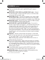
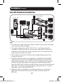
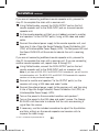
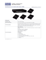
Non-Kit Standard Installation
Note:
1. For models that support EDID copy, perform the EDID copy procedure described
in this manual prior to installation.
2. The diagram above shows a B132-004A-2 VGA + Audio Extender/Splitter
installation. Installation will be the same for non-audio models, except that an
audio source and speakers will not be connected. Also, the number of ports on
transmitters will vary from 2 to 4 to 8.
3. Test to make sure the entire installation works properly before pulling cables
through ceilings/walls.
4. To achieve maximum distance and performance, 24 AWG solid-wire Cat5e/6
cable must be used. The use of stranded wire Cat5e/6 cable, or cable with a
gauge (AWG) size higher than 24 AWG, will result in shorter extension distance.
All Tripp Lite N202-Series cables are made with 24 AWG solid-wire cabling.
Tripp Lite N022-01K-GY (Cat5e) and N222-01K-GY (Cat6) are 24 AWG solid-wire
bulk cables. For optimal image quality between 500 and 1,000 ft., use Zero-
Skew cable, such as Tripp Lite P524-01K.
5. To achieve maximum resolution, it is recommended that you use Tripp Lite
P502-Series VGA video or P504-Series VGA video and audio cables with
RGB coax.
Source PC
B132-100A-WP-1B132-004A-2
B132-100A
15-08-104-933289-EN.indd 17 8/21/2015 3:45:49 PM

18
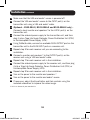
1
Make sure that the VGA and audio* source is powered off.
2
Connect the VGA and audio* source to the INPUT port(s) on the
transmitter unit using a VGA and audio* cable.
3
(Optional – B132-004-2, B132-004A-2 and B132-008A-2 only)
–
Connect a local monitor and speakers* to the LOCAL port(s) on the
transmitter unit.
4
Connect the external power supply to the transmitter unit, and then
plug it into a Tripp Lite Surge Protector, Power Distribution Unit (PDU)
or Uninterruptible Power Supply (UPS).
5
Using Cat5e/6 cable, connect an available RJ45 OUTPUT port on the
transmitter unit to the RJ45 INPUT port on a receiver unit.
6
Repeat step 5 for each receiver unit you are connecting to the
installation.
7
Connect a monitor and speakers* to the OUTPUT port(s) on the
receiver unit using a VGA and audio* cable.
8
Repeat step 7 for each receiver unit in the installation.
9
Connect the external power supply to the receiver unit, and then plug
it into a Tripp Lite Surge Protector, Power Distribution Unit (PDU) or
Uninterruptible Power Supply (UPS).
10
Repeat step 9 for each receiver unit in the installation.
11
Turn on the power to the monitor and speakers.*
12
Turn on the power to the monitor and audio* source.
13
If necessary, adjust the Equalization and Gain controls using the
included screwdriver to improve the video image.
Installation continued
*If this is a feature of your extender kit.
15-08-104-933289-EN.indd 18 8/21/2015 3:45:50 PM

19
Installation continued
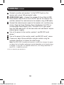
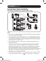
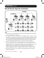
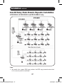
Non-Kit Daisy Chain Installation
(B132-004-2, B132-004A-2 and B132-008A-2 only)
Note:
1. For models that support EDID copy, perform the EDID copy procedure described
in this manual prior to installation.
2. The diagram above shows a B132-004A-2 VGA + Audio Extender/Splitter daisy
chain installation. Installation will be the same for non-audio models, except that
an audio source and speakers will not be connected. Also, the number of ports
on transmitters will vary from 4 to 8.
3. Test to make sure the entire installation works properly before pulling cables
through ceilings/walls.
4. To achieve maximum distance and performance, 24 AWG solid-wire Cat5e/6
cable must be used. The use of stranded wire Cat5e/6 cable, or cable with a
gauge (AWG) size higher than 24 AWG, will result in shorter extension distance.
All Tripp Lite N202-Series cables are made with 24 AWG solid-wire cabling.
Tripp Lite N022-01K-GY (Cat5e) and N222-01K-GY (Cat6) are 24 AWG solid-wire
bulk cables. For optimal image quality between 500 and 1,000 ft., use Zero-
Skew cable, such as Tripp Lite P524-01K.
5. To achieve maximum resolution, it is recommended that you use Tripp Lite P502-
Series VGA video or P504-Series VGA video and audio cables with RGB coax.
Source PC
Local PC and
Speakers (Optional)
B132-100A-WP-1
B132-004A-2
B132-100A
15-08-104-933289-EN.indd 19 8/21/2015 3:45:50 PM

20
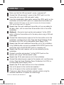
1
Make sure that the VGA and audio* source is powered off.
2
Connect the VGA and audio* source to the INPUT port(s) on the
transmitter unit using a VGA and audio* cable.
3
Using the included daisy chain cable, connect the LOCAL port(s) on the
transmitter unit to the INPUT ports on a second-level transmitter unit.
Note: A standard VGA cable can be used to increase the distance between
units with no more than 6 ft. between.
4
Repeat step 3 for each additional transmitter unit you are adding to
the daisy chain, with no more than 6 transmitter units in the entire
installation.
5
(Optional) – Connect a local monitor and speakers* to the LOCAL
port(s) of the last transmitter unit in the daisy chain using a VGA and
audio cable.
6
Connect the external power supply to the first transmitter unit in the
installation, and then plug it into a Tripp Lite Surge Protector, Power
Distribution Unit (PDU) or Uninterruptible Power Supply (UPS).
7
Repeat step 6 for each additional transmitter unit in the installation.
8
Using Cat5e/6 cable, connect an available RJ45 OUTPUT port on the
transmitter unit to the RJ45 INPUT port on a receiver unit.
9
Repeat step 8 for each receiver unit you are connecting to the
installation.
10
Connect a monitor and speakers* to the OUTPUT ports on the
receiver unit using a VGA and audio* cable.
11
Repeat step 10 for each receiver unit in the installation.
12
Connect the external power supply to the receiver unit, and then plug
it into a Tripp Lite Surge Protector, Power Distribution Unit (PDU) or
Uninterruptible Power Supply (UPS).
13
Repeat step 12 for each receiver unit in the installation.
14
Turn on the power to the monitor and speakers.*
15
Turn on the power to the monitor and audio* source.
16
If necessary, adjust the equalization and gain controls using the
included screwdriver to improve the video image.
Installation continued
*If this is a feature of your extender kit.
15-08-104-933289-EN.indd 20 8/21/2015 3:45:50 PM
Page is loading ...
Page is loading ...
Page is loading ...
Page is loading ...
Page is loading ...
Page is loading ...
Page is loading ...
Page is loading ...
Page is loading ...
Page is loading ...
Page is loading ...
Page is loading ...
Page is loading ...
Page is loading ...
Page is loading ...
Page is loading ...
-
 1
1
-
 2
2
-
 3
3
-
 4
4
-
 5
5
-
 6
6
-
 7
7
-
 8
8
-
 9
9
-
 10
10
-
 11
11
-
 12
12
-
 13
13
-
 14
14
-
 15
15
-
 16
16
-
 17
17
-
 18
18
-
 19
19
-
 20
20
-
 21
21
-
 22
22
-
 23
23
-
 24
24
-
 25
25
-
 26
26
-
 27
27
-
 28
28
-
 29
29
-
 30
30
-
 31
31
-
 32
32
-
 33
33
-
 34
34
-
 35
35
-
 36
36


Tripp Lite VGA over Cat5 Extenders/Splitters 9 Owner's manual
- Category
- AV extenders
- Type
- Owner's manual
Ask a question and I''ll find the answer in the document
Finding information in a document is now easier with AI
Related papers
-
Tripp Lite B132-002A-2 Owner's manual
-
Tripp Lite VGA Over Cat5 Extenders and Extender/Splitters User manual
-
Tripp Lite B130-101-U Owner's manual
-
Tripp Lite B140-101X-U DVI over Cat5 Extender Kit Owner's manual
-
Tripp Lite VGA Over Cat5 Extender Kits Owner's manual
-
-
-
-
Tripp Lite B126-1A1-POC Owner's manual
-
Tripp Lite B132-100A Owner's manual
Other documents
-
 Cables Direct VGA-V180 Datasheet
-
 StarTech.com PANEL4524 Datasheet
-
 Cables Direct VGA-VART300QD Datasheet
-
Black Box AC2000A Datasheet
-
AVLink VGA-EDXW PRO Owner's manual
-
Eminent AB7862 Datasheet
-
 StarTech.com PANEL4512 Datasheet
-
Newstar NS121UTP Specification
-
Hubbell Wiring Device-Kellems PD2793 Installation guide
-


