Rocktron EN50082-1 Owner's manual
- Category
- Audio equalizers
- Type
- Owner's manual
This manual is also suitable for

24-BIT DIGITAL SIGNAL PROCESSOR
USER'S MANUAL
May be covered by one or more of the following: U.S. Patents #4538297, 4647876, 4696044, 4745309, 4881047, 4893099, 5124657,
5263091, 5268527, 5319713, 5333201, 5402498, 5493617 and 5638452. Other patents pending. Foreign patents pending.

Copyright ©1997 Rocktron Corporation. All rights reserved.
Your Intellifex
®
XL has been tested and complies with the following Standards and Directives as set forth by the
European Union:
Council Directive(s): 89/336/EEC Electromagnetic Compatibility
Standard(s): EN55013, EN50082-1
This means that this product has been designed to meet stringent guidelines on how much RF energy it can emit,
and that it should be immune from other sources of interference when properly used. Improper use of this equip-
ment could result in increased RF emissions, which may or may not interfere with other electronic products.
To insure against this possibility, always use good shielded cables for all audio input and output connections.
Also, bundle audio cables separately from the AC power cables. These steps will help insure compliance with the
Directive(s).
For more information about other Rocktron products, please see your local dealer or one of our importers closest
to you (listed on the enclosed warranty sheet).
PRECAUTIONS
NOTE: IT IS VERY IMPORTANT THAT YOU READ THIS SECTION TO PROVIDE YEARS OF TROUBLE FREE USE.
THIS UNIT REQUIRES CAREFUL HANDLING.
All warnings on this equipment and in the operating instructions should be adhered to and all operating instructions
should be followed. Do not use this equipment near water. Care should be taken so that objects do not fall and liquids
are not spilled into the unit through any openings. The power cord should be unplugged from the outlet when left
unused for a long period of time.
DO NOT ATTEMPT TO SERVICE THIS EQUIPMENT. THIS EQUIPMENT SHOULD BE SERVICED BY QUALIFIED
PERSONNEL ONLY. DO NOT MAKE ANY INTERNAL ADJUSTMENTS OR ADDITIONS TO THIS EQUIPMENT AT
ANY TIME. DO NOT TAMPER WITH INTERNAL ELECTRONIC COMPONENTS AT ANY TIME. FAILURE TO
FOLLOW THESE INSTRUCTIONS MAY VOID THE WARRANTY OF THIS EQUIPMENT, AS WELL AS CAUSING
SHOCK HAZARD.
POWER REQUIREMENTS
This unit accepts power from the 9VAC/1.5A adaptor supplied with the unit. This 9 volt RMS AC voltage is internally
processed by a voltage doubler which generates a bipolar ±15 volts to maintain the headroom and sound quality of
professional, studio quality equipment. Using an external power source such as this minimizes excessive noise and hum
problems often associated with internal transformers, providing optimal performance for the user.
OPERATING TEMPERATURE
Do not expose this unit to excessive heat. This unit is designed to operate between 32° F and 104° F (0° C and 40° C).
This unit may not function properly under extreme temperatures.

Contents
1. Introduction .................................................................................................................................. 1
2. Quick Setup .................................................................................................................................. 2
3. Front Panel ................................................................................................................................... 3
4. Rear Panel .................................................................................................................................... 5
5. Connections ................................................................................................................................. 6
6. Function/Parameter Descriptions ............................................................................................... 9
MIXER Function ...................................................................................................................................... 9
EQ Function .......................................................................................................................................... 11
HUSH Function ...................................................................................................................................... 12
REVERB Function ................................................................................................................................. 13
DELAY Function .................................................................................................................................... 15
DUCKER Function ................................................................................................................................. 17
VOICE/DLY Function ............................................................................................................................ 18
7. Configurations ........................................................................................................................... 21
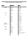
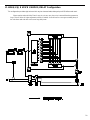
A. HUSH; EQ; CHORUS; DELAY; REVERB Configuration .................................................................. 22
B . HUSH; EQ; REVERB Configuration ................................................................................................ 24
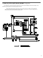
C. HUSH; EQ; DELAY; DUCKER Configuration .................................................................................... 26
D. HUSH; EQ; 8 VOICE CHORUS; DELAY Configuration .................................................................... 29
E. HUSH; EQ; PITCH SHIFT; DELAY Configuration ............................................................................ 31
F. HUSH; EQ; PITCH SHIFT; DELAY; REVERB Configuration ............................................................ 33
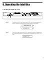
8. Operating the Intellifex .............................................................................................................. 35
A. Recalling an Intellifex XL preset ....................................................................................................... 35
B. Changing preset parameters ............................................................................................................. 36
C. Storing modified parameter values ................................................................................................... 37
D. Editing a preset title .......................................................................................................................... 39
E. Selecting a Power On preset ............................................................................................................ 40
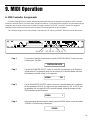
9. MIDI Operation ........................................................................................................................... 41
A. MIDI Controller Assignments ............................................................................................................ 41
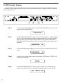
B. MIDI Program Mapping ..................................................................................................................... 44
C. MIDI Channel .................................................................................................................................... 46
D. MIDI Dump/Load ............................................................................................................................... 47
E. Factory Restore ................................................................................................................................ 53
10. Appendix .................................................................................................................................. 54
A. MIDI Implementation Chart ............................................................................................................... 54
B. Specifications ................................................................................................................................... 55

1
The Rocktron Intellifex
®
XL is a 24-bit digital effects processor utilizing two 20-bit con-
verters and Sigma-Delta A/D conversion, achieving a 64x oversampling rate and better than
100dB dynamic range. The Intellifex XL is totally programmable and allows for complete
MIDI control. The unit features pitch shifting, 8 voice stereo chorusing effects, digital delay
effects including 2-tap, stereo and ping ponging effects, unsurpassed digital reverb quality
and highly flexible configuration programming allowing for simultaneous operation of up to 5
effects plus complete mixing capabilities. The unit also offers Hush Systems’ first fully digital
implementation of patented HUSH
®
noise reduction at the unit’s input, along with delay and
reverb ducking capabilities.
For a thorough explanation of the Intellifex
®
XL and its functions, please read this manual
carefully and keep it for future reference. A better understanding of how the Intellifex
®
XL
operates will help make designing your own preset sounds much easier.
After removing the Intellifex
®
XL from the box, save all packing materials in case it
becomes necessary to ship the unit.
What makes the Intellifex
®
XL unique?
* Super quiet operation due to use of digital HUSH
®
and high quality 20-bit converters.
* High purity sound due to the use of a 64X oversampling A/D converter, which samples the
signal 64 times as often as a conventional converter, and also due to the use of a separate
dual D/A converter. Most "bargain" digital effects units use a single converter multiplexed 3
ways, for decidedly higher distortion and lower dynamic range.
* 24-Bit processing and memory circuits to maintain maximum dynamic range.
* Ability to store up to 8 unique MIDI controller patches with each preset.
* Very high quality effects algorithms.
* Highly stereo effects with panning available on almost all signals.
* 8 Voice chorusing with an enormous number of parameters for the richest chorus ever.
* High quality 4 voice pitch shifting over 3 full octaves.
* 2-voice pitch shifting or 4-voice chorusing offered simultaneously with Hush
®
, Delay and
Reverb.
* Double-precision 4-band parametric EQ
* Programming via knobs instead of push buttons.
* Easy to read, wide viewing angle display.
1. Introduction

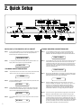
2
2. Quick Setup
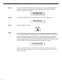
STEP 3 Now press the STORE button a second time to store the modified values
into the selected preset location. The Intellifex XL will display "STORED"
briefly before displaying the new preset number/title.
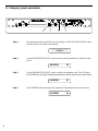
RECALLING A STORED INTELLIFEX XL PRESET
STEP 1 To recall a stored Intellifex XL preset, first turn the PRESET control to the
desired preset number you wish to recall. The display will alternate
between the preset number/title selected and:
PRESS RECALL FOR
STEP2 To call up the preset you have selected, press the RECALL button. The
display will now show only the new preset number/title.
14 PRESET TITLE
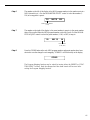
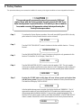
CHANGING PRESET PARAMETERS
STEP 1 The parameter menu for each effect can be called up via the FUNCTION
SELECT control. Turn this control to the effect to be changed.
**** REVERB ****
STEP 2 Turn the PARAMETER SELECT control to select which parameter select
the parameter to be modified.
REV DECAY 59
STEP 3 Use the PARAMETER ADJUST control to modify the parameter value.
The LED above the STORE button lights to indicate that a parameter
value has been modified from the stored preset.
REV DECAY 32
STEP 4 The COMPARE button may be used to compare the stored value to the
new one.
REV DECAY 59
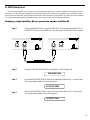
STORING MODIFIED PARAMETER VALUES
STEP 1 To store modified parameter values, press the STORE button while
viewing a parameter or effect title to begin the store procedure. The
Intellifex XL will alternate displaying the current preset number/title and:
STORE TO PRESET
STEP 2 Turn the PRESET control to select the desired preset number to store the
new parameter values into (if the new values are to be stored into the
current preset location, this step is not necessary). User presets may be
stored in preset locations 1-80. Presets 81-160 are factory presets and
cannot be copied over. The Intellifex XL will now alternate displaying the
new preset number/title and:
STORE TO PRESET
STORED
STEP 4 After the modified parameters have been stored into a new preset
location, the Intellifex XL will display "COPY TITLE TOO?". This occurs
only when a new preset location is selected to store the modified
parameters into, and allows for the title from the original preset to be
copied to the new preset location as well. To copy the title, press the
STORE button a third time. The display will again flash "STORED".
NOTE 1 If it is not desired to copy the title from the original preset, turn either the
PRESET or FUNCTION SELECT control to exit the store procedure.
NOTE 2 If a modified preset is edited without completing the store procedure (i.e.
"STORED" displayed at least one time), all edited parameter values will
be lost and the preset will revert to its original condition the next time it is
recalled. When saving altered parameters, always make sure the Intellifex
XL flashes "STORED" at least once before exiting the preset to ensure
that the desired modifications were stored into memory.

3
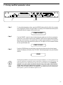
Some of the controls on the Intellifex XL front panel have more than one function, dependent
upon what mode the unit is currently operating in. Please read this section to become better
aquainted with these functions.
1) POWER switch
2) RECALL button:
This button recalls the displayed preset.
3) PRESET control:
The function of this control is dependent on status of the CONFIG button.
When the CONFIG LED is off, turning the PRESET control will cause the Intellifex XL to
exit its current function. The PRESET control may then be used to scroll through the
successive factory and user presets and titles stored in its memory.
When the CONFIG LED is on, the PRESET control is again used to scroll through the
successive presets, but instead of displaying preset titles the Intellifex XL will display the
effect configuration stored for each preset.
4) CONFIG button:
The CONFIG button is used to toggle between displaying either the preset title or the
configuration of the currently displayed preset. The configuration display indicates both
which effects the displayed preset executes and the order in which they are executed. The
LED above the CONFIG button is lit when the configuration is displayed.
5) DISPLAY panel:
The DISPLAY panel consists of 16 characters. Each character consists of 14 segments.
6) COMPARE button:
The COMPARE button may be used to compare a modified parameter value to its stored
value. (If comparing an altered value to the stored value and the stored value is currently
being viewed, turning a knob or pressing a button that changes the parameter value
displayed will cancel the previous modified value.)
The COMPARE button may also be used to simultaneously compare multiple modified
parameters under the same effect heading (i.e. Reverb, Mixer, etc.) to the stored values. To
do so, turn to the effect heading where the modified parameters are located and press the
COMPARE button. When the STORE LED is off, the stored parameter values are currently
active. When the STORE LED is lit, the modifed values are active.
If a knob is turned or a button is pressed which changes the effect heading when the stored
parameters are active (STORE LED off), any modified parameter values under that heading
will be lost. This is also true if a MIDI control change is received while the stored
parameters are active.
3. Front Panel

4
7 PARAMETER ADJUST control:
This control is used to adjust the displayed parameter value. When the parameter is changed
from its original value, the LED above the STORE button will light until either (a) the new
value is stored, (b) a new preset is selected or (c) the parameter is returned to its original
value.
8) STORE button:
This button is used to store values into the Intellifex XL memory when modified. See
"Storing Modified Parameters" in Chapter 8 for more information.
9) PARAMETER SELECT control:
When monitoring parameter values, this control scrolls through the available parameters
under the current effect heading.
In the "TITLE EDlT" function, this control scrolls through the available characters in the
title that may be edited.
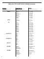
10) FUNCTION SELECT control:
This control allows access to each function of the Intellifex XL. Depending on which
configuration the current preset is built upon, these functions may include:
Preset Select Reverb Mixer
HUSH EQ MIDI Controller Mapping
Chorus Delay MIDI Program Mapping
Pitch Shift Ducker MIDI Channel
Title Edit Factory Restore MIDI Dump/Load
11) BYPASS button:
When pressed, the LED is lit and all effects are bypassed.
12) INPUT LEVEL meter:
These LEDs provide visual indication of the peak level of the input signal. For the optimal
signal-to-noise ratio, it is best to adjust the input level so that the last LED (0dB) is rarely lit.
This will guard against the possibility of overdriving the unit.
13) INPUT LEVEL control:
This control adjusts the unit's gain to match the signal level at the input of the Intellifex XL.
The gain can be adjusted from -12dB to +12dB. Use the INPUT LEVEL meter to determine
the setting of this control.
14) CLIP L.E.D.:
This L.E.D. is part of the output section and, when lit, indicates that the final analog output
is being overdriven because the Effects Level, Direct level, and Output Level control are set
too high. If this occurs, reduce these levels until this L.E.D. does not light.
15) OUTPUT LEVEL control:
This control is used to adjust the output level of the unit and may be adjusted from zero
signal to a small amount of gain.
16) REFERENCE LEVEL switch:
This switch determines the output range of the unit and may be set at either -10dB or +4dB.
When using professional studio equipment providing a nominal input level of +4dB, it is
recommended that the +4 setting on the Intellifex XL be used for best results. If connecting
the Intellifex XL to a high sensitivity input, such as the input to a guitar amp, the -10 setting
should be used.

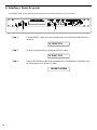
5
1) R(MONO) INPUT jack:
This standard 1/4" mono jack provides input to the right channel of the Intellifex XL. When
using only one input (mono), this jack should be used.
2) L INPUT jack:
This standard 1/4" mono jack provides input to the left channel of the Intellifex XL. When
using only one input, this jack should not be used.
3) R OUTPUT jack:
This standard 1/4" mono jack provides an output for the right channel of the Intellifex XL.
When using the unit in a mono application, either output jack may be used.
4) L OUTPUT jack:
This standard 1/4" mono jack provides output for the left channel of the Intellifex XL. When
using the unit in a mono application, either output jack may be used.
5) PHANTOM POWER jack:
This jack offers the ability to power the Rocktron MIDI Mate
™
Foot Controller from a seven
pin MIDI cable which connects from the MIDI Mate to the MIDI IN jack on the rear panel
of the Intellifex XL, eliminating the need to find an AC outlet near where the footpedal
would be placed during a performance - or the need to run an extension cord out to the
MIDI Mate. Instead of inserting the adaptor into the MIDI Mate
™
POWER jack, plug it into
the PHANTOM POWER jack on the Intellifex XL. This will power the MIDI Mate
™
through pins 6 and 7 of the MIDI cable connecting the two units. A 7-pin MIDI cable must
be used and is available through your Rocktron dealer.
6) MIDI IN jack:
This 7-pin DIN connector receives MIDI information from the device which is transmitting
the MIDI commands for the Intellifex XL to execute.
7) MIDI OUT/THRU jack:
This standard 5-pin DIN connector passes on the MIDI information that is received at the
MIDI IN jack to other MlDI-compatible devices via a MIDI cable. It also outputs MIDI data
when performing a memory dump.
Note: Inherently in MIDI there is a limit to the number of devices which can be chained
together (series connected). With more than three devices, a slight distortion of the MIDI
signal can occur (due to signal degradation) which can cause an error in MIDI signal
transmission. Should this problem arise, a MIDI box can be used which connects directly to
the MIDI device which transmits MIDI information and has multiple connectors for the
multiple devices receiving MIDI. MIDI cables should not exceed 50 feet (15 meters) in
length.
8) POWER jack:
This jack accepts power from the 9VAC/1500mA adaptor supplied with the unit.
4. Rear Panel
G
Note
When using a mono input and a
mono output, the left and right
effect signals will be summed at
the single output.

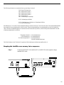
6
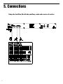
5. Connections
Using the Intellifex XL with the auxiliary sends and returns of a mixer

7
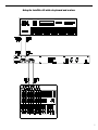
Using the Intellifex XL with a keyboard and a mixer

8
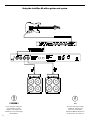
Using the Intellifex XL with a guitar rack system
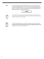
Note
For best results when using the
Intellifex XL with high gain
distortion, always put the
Intellifex XL after the distortion in
the signal chain, never before it.
G
!
!! CAUTION !!
Never connect the outputs of a
power amplifier or guitar
amplifier to the inputs of the
Intellifex XL. This could damage
the Intellifex XL.

9
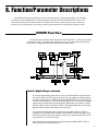
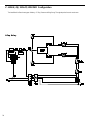
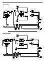
6. Function/Parameter Descriptions
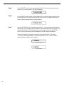
Caution: Digital Output overload
As the input signal enters at the unit’s input (A), the unaltered direct signal is fed to
the Direct Pre/Post HUSH
®
Selector (B). Here you may choose for the direct signal
to remain unaltered (Pre) or feed it through the digital HUSH
®
(E) and 4-band EQ (F)
sections of the Intellifex XL (Post). Before being fed to the HUSH
®
section, the signal
must first be converted from an analog signal to digital via the converter (D). When
the direct signal is fed to the HUSH
®
section, it will remain digital until it is summed
together with the output of the Effects Level control (H).
It is important to remember that it is possible to overload the Digital to Analog
Converter (I) if the effects levels and direct signal level are set too high when using
the
HUSH
®
section with the direct signal. If this occurs, reduce these levels until the
front panel CLIP L.E.D. does not light.
Also note that when passing the direct signal through the digital HUSH
®
(Post), a
stereo signal will be converted to mono.
The first function accessible when turning the FUNCTION SELECT control in any preset
is the Mixer function. This digital mixer allows you to control the signal levels pertaining to
each preset’s configuration and stores these levels for each preset.
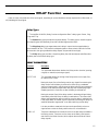
MIXER Function
The Intellifex provides many parameters to achieve the widest variety of preset sounds possible. The parameters
available for a given configuration are divided into sections accessible via the FUNCTION SELECT control. This
section will discuss each of the functions that are available which relate to a preset's overall sound. Utility-based
functions, such as MIDI operation, title editing, and factory preset restoration, are described in Chapters 8 and 9.

10
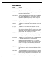
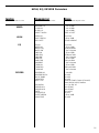
Mixer Parameters
Parameter Description
EFFECT LVL
This controls the level of the entire effect signal. This control should be
set relative to the levels of the Left and Right Direct signals. In configu-
rations which do not include a master Effects Level, the single effect
level parameter (Chorus Level, Delay Level, etc.) is considered the
master Effect Level control.
L/R DIR LEVEL
These controls allow for the left and right Direct signal levels to be set
individually, thereby allowing for panning of the Direct signal to the left or
right output. These controls are available in all configurations.
DIRECT HUSH
This determines whether the direct signal passes through the digital
HUSH
®
section of the Intellifex XL or bypasses it. Selecting "Post" will
pass the Direct signal through the HUSH
®
system while selecting "Pre"
will bypass this section. (Note: Selecting "Post" converts a stereo direct
signal to mono.)
CHORUS LVL,
In configurations which include a Master Effects Level control, these
DELAY LVL,
control the level of each individual effect (Chorus, Reverb, etc.).
REVERB LVL,
These should be set relative to each other when defining individual
etc.
levels. In configurations which do not include a Master Effects Level
control, the individual effect level acts as a Master effect level.
REGEN L/R
Configurations which include chorus or delay effects provide individual
left and right regeneration level controls to determine the number of
times the delayed signals are repeated. Regeneration is achieved by
feeding the delayed output back into the input. Higher levels of regen-
eration will result in more repeats.
Note that the Intellifex XL provides
Regeneration Limiting.
This feature
guards against the possibility of overloading the processor when using
high regeneration levels in configurations where a combination of
multiple voices is panned to the left or right. If the regeneration level is
set too high, the Intellifex XL triggers the Regeneration Limiting and a
limit is internally set for the regeneration. This limit can not be exceeded
by increasing the
Regen L
or
Regen R
parameter values in the Mixer
section.
If, for example, in the
Hush; Chorus; Delay; Reverb
configuration, Voice
1 is panned to the left and the
Regen L
parameter is set to its maximum
level, panning a second voice to the left regeneration loop will trigger the
Regeneration Limiter and reduce the regeneration to a level such that
runaway regeneration will not occur. The original regeneration level can
be reset only by recalling the preset, or, by accessing the
Regen L
parameter, decreasing its value and setting it back to its original value
after removing the second Voice from the regeneration loop. This
feature of the Intellifex XL is particularly desirable in live situations
where panning and regeneration levels may be controlled by continuous
controllers.

11
EQ Function
The EQ function is available in all presets—regardless of the current configuration. The Intellifex XL provides four
bands of double-precision parametric EQ for all configuration types. Each band provides adjustable level, frequency and
bandwidth parameters.
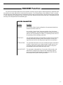
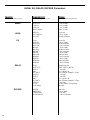
EQ Parameters
Parameter Description
EQ I/O
The EQ can be inserted or removed from the signal chain (IN or OUT).
BASS LVL
The BASS LEVEL parameter can be used to cut or boost the low
frequencies by up to 15dB.
BASS FRQ
The BASS FREQUENCY parameter specifies a center frequency
between 21Hz and 500Hz to be cut or boosted by the BASS LVL
parameter.
BASS BW
The BASS BANDWIDTH parameter specifies (in octaves) the width of
the selected bass band.
LMID LVL
The LOW MID LEVEL parameter can be used to cut or boost the low
mid-band frequencies by up to 15dB.
LMID FRQ
The LOW MID FREQUENCY parameter specifies a center frequency
between 250Hz and 2kHz to be cut or boosted by the LMID LVL param-
eter.
LMID BW
The LOW MID BANDWIDTH parameter specifies (in octaves) the width
of the selected low mid-band.
HMID LVL
The HIGH MID LEVEL parameter can be used to cut or boost the high
mid-band frequencies by up to 15dB.
HMID FRQ
The HIGH MID FREQUENCY parameter specifies a center frequency
between 1kHz and 8kHz to be cut or boosted by the HMID LVL param-
eter.
HMID BW
The HIGH MID BANDWIDTH parameter specifies (in octaves) the width
of the selected high mid-band.
TREB LVL
TheTREBLE LEVEL parameter can be used to cut or boost the high
frequencies by up to 15dB.
TREB FRQ
The TREBLE FREQUENCY parameter specifies a center frequency
between 2kHz and 16kHz to be cut or boosted by the TREBLE LVL
parameter.
TREB BW
The TREBLE BANDWIDTH parameter specifies (in octaves) the width
of the selected high band.

12
HUSH Function
HUSH
®
is Rocktron's patented single-ended noise reduction system. The HUSH
®
system contained in the Intellifex XL
is a fully digital implementation of HUSH achieved through Digital Signal Processing (DSP), and is modeled after the latest
HUSH design.
The low level expander of the HUSH
®
system operates like an electronic volume control. The analog design utilizes a
voltage-controlled amplifier (VCA) circuit which can control the gain between the input and output from unity to 30, 40 or
even 50dB of gain reduction. When the input signal is above the user preset threshold point, the VCA circuit is at unity
gain. This means that the amplitude of the output signal will be equal to that of the input signal. As the input signal ampli-
tude drops below the user preset threshold point, downward expansion begins. At this point the expander operates like an
electronic volume control and gradually begins to decrease the output signal level relative to the input signal level. For
example, if the input signal were to drop below the threshold point by 2dB, the output would drop approximately 3dB. As
the input signal drops further below the threshold point, downward expansion increases. For example, if the input signal
dropped 6dB below the threshold point, the output level would drop by approximately 14dB. A drop in the input level by
20dB would cause the output level to drop by approximately 54dB (i.e. 34dB of gain reduction). In the absence of any input
signal, the expander will reduce the gain such that the noise floor becomes inaudible.
HUSH
®
Parameters
Parameter Description
HUSH I/O
This parameter determines whether the HUSH
®
circuit will be in the
signal path or bypassed.
EXP THRESH
The Expander Threshold parameter determines the level at which
downward expansion begins. For example, if the expander threshold
was set at -20dB and the input signal dropped below -20dB, downward
expansion would begin. Typically, this parameter should be set between
5-20dB above the quiescent noise floor of the input signal (i.e. if the
noise floor was -60dB, a setting between -40 and -55dB will produce the
proper expansion).
REL RATE
The Release Rate parameter determines the amount of time required
for the downward expander to decrease the level of the output signal.
This rate is adjustable from 25mS to 800mS to accommodate a wide
variety of applications. For example, when using the expander for gating
applications on drums, a very quick release rate (25-200mS) should be
used. When used with individual instruments such as guitar, a setting of
200mS or higher will provide adequate expansion without being as
harsh as a gate. When used with sources which have long decay times
(cymbals, etc.) a very slow release rate should be used.

13
REVERB Function
Reverb, or reverberation, is the continuance of sound within a given room or enclosed chamber after the source of the
sound has stopped producing it. More specifically, it is a multitude of echoes so densely spaced that, to the human ear,
seem as a single continuous sound. These echoes gradually decrease in intensity until they are ultimately absorbed by the
boundaries and obstacles within the room or enclosure. As the sound waves from the signal source strike the walls or
boundaries of the room, a portion of the energy is reflected away from the obstacle and another portion is absorbed into it,
thereby causing both the continuance of sound and the decaying or "dying out" of the sound.
Reverb Types
The Intellifex XL HUSH; REVERB configuration offers 8 different reverb types:
Plate A
,
Plate
B
,
Room A
,
Room B
,
Hall A
,
Hall B
,
Stadium
and
Dual
.
The Plate reverb type simulates an artificial method of producing reverberation, popular in
the early years of recording, which involved using a fairly large, but very thin, metal plate
suspended at its four corners by steel wires under tension. This metal plate becomes excited
by a driver unit (similar to a dynamic speaker without the diaphragm) and the resulting
reverberation is picked up by contact microphones.
The Intellifex XL offers two Plate reverb types which reflect the most common plate charac-
teristics. This type of reverb is often used on drum and vocal tracks.
Room reverb effects simulate various rooms of different sizes and surfaces. For example, a
room which is made up of primarily hardened surfaces (such as tile or hard wood) will
generate reflections containing much more high frequency information than one which is
made up of softer surfaces (such as thick carpeting). The Room reverb effects offered by the
Intellifex XL can generate virtually any imaginable room setting via highly efficient and
adjustable reverb parameters.
Hall reverb simulates the reverberation characteristics of a very large room with a high
ceiling. Reflections in a hall are much longer than a typical room, as the length of time it
takes for the sound waves to travel from one surface to the next is greatly increased.
Stadium reverb simulates the characteristics of a large stadium or arena and should be
used with large amounts of predelay and high frequency damping.
Dual reverb is unique in that it allows for the left and right channels to be processed indepen-
dently one another. For example, the Predelay for the left channel can be set at 100mS while
the Predelay for the right channel can be set at 200mS. This results in reverb output from the
left channel 100mS before reverb is output from the right channel.

14
Reverb Parameters
Parameter Description
REVERB INPUT
This determines whether the input to the reverb section is
active
(pass-
ing a signal) or
muted
(not passing a signal).
REVERB LVL
This determines the level of the reverb signal at the output relative to the
direct signal and any other effect signals. It is accessible from both the
Mixer function and Reverb function.
REVERB DECAY
This specifies the length of time that the reverb signal will sound before
it has completely faded out (or until its echoes have been ultimately
absorbed by the boundaries within the given "room"). The maximum
length of this decay will vary dependent upon which reverb type is
active.
RV HF DAMP
High Frequency Damping is used to control the amount of high fre-
quency information in the reverb signal.
LOW FREQ
This determines the amount of low frequency information in the reverb
signal.
REV TYPE
This determines the current active reverb type (Room, Plate, etc.).
DIR IN PAN
This allows you to pan the direct input signal to the reverb section to the
left or right - allowing for only the left or right channel to be reverberated
when used with the Dual reverb type, or, for one channel to be reverber-
ated to a greater degree than the other. It is adjustable from 0 to 100—
where "0" = full left, "100" = full right and "50" = center.
PREDELAY L
This determines the amount of time after a signal is input to the Intellifex
XL that the left channel signal will be input to the Reverb. Delaying the
reverb signal provides greater separation of the input and reverb signals
and helps to increase the apparent size of the Room, Hall, or Stadium.
PREDELAY R
This determines the length of time after a signal is input to the Intellifex
XL that the right channel signal will be input to the Reverb.
GATE
Gating the reverb signal closes down the decay of the reverb very
quickly after a prescribed amount of time (most commonly a very short
period of time). This effect is often used on drums (particularly snare
drums) to produce the effect of a much fatter percussive sound. Note
that gating on the Intellifex XL acts on the reverb decay, not on the
reverb output as on many other units.
GATE DECAY
The Gate Decay parameter determines how quickly the gate will close
down the reverb decay after the reverb has sounded for the specified
time.
GATE THRESH
The Gate Threshold determines the threshold point at which gating will
take place. When the signal is below this threshold point for a period of
time, the reverb will be gated. When the input signal peak rises above
this threshold, the gate will open and reverb will be heard.
HOLD TIME
The Hold Time determines how long the reverb signal will sound before
the gate begins to close.

15
DELAY Function
Delay is simply a reproduction of the input signal, originating at a prescribed time (usually expressed in milliseconds, or
mS) following the input signal.
Delay Types
The Intellifex XL HUSH; Delay; Ducker configuration offers 3 delay types: Stereo, Ping-
Pong and 2-Tap.
The Stereo delay type provides two separate delays. This delay type is used for applica-
tions requiring two discrete delay lines with individual regeneration loops.
The Ping-Pong delay type regenerates each delay’s output into the opposite delay’s
input instead of its own. This causes the delayed signals to bounce back and forth from the
left channel to the right (provided the delay outputs are panned left and right).
The 2-Tap delay type provides a single long delay line with two outputs and offers twice
the delay time of the Stereo delay type.
DELAY PARAMETERS
Parameter Description
DELAY
This parameter determines whether the Delay section is active (passing
a signal) or muted (not passing a signal).
MUTE TYPE
This parameter allows for muting of the Delay section at its input (Pre),
its output (Post) or both.
Muting the input (Pre) of the Delay restricts any signal from entering the
delay section until the delay is switched in. When using a moderate
amount of regeneration, switching out the delay with the input muted will
generate a non-delayed signal which will play over the decaying regen-
erated signal which continues on after the delay is switched out.
Muting the output (Post) of the delay results in the delayed signal being
immediately turned off when the delay is switched out. This means that
delays and regeneration will not continue once the delay is switched out.
If the output were
not
muted, signals input before switching the delay out
would be allowed to regenerate - even after switching out the delay.
It is also possible to mute both the input and output (Both) so that no
signal enters or exits the Delay section when it is not switched in.
LEVEL 1/2
These are individual level controls for each of the two delays available in
the Delay section. These are not the same as the Delay Level param-
eter found in the Mixer function (which adjusts the overall level of both
delay signals).

16
PAN 1/2
This allows for the panning of each delay to the left or right output, if
desired. The Pan parameter is adjustable from 0 to 100 - where 0 = full
left, 100 = full right and 50 = center.
DLY TIME 1/2
These parameters determine the amount of time after a signal is input
that the delayed signal will begin to reproduce the input signal.
REGEN 1/2
This parameter is provided for each delay and determines the number of
times the delayed signal will repeat itself. This is achieved by feeding the
delayed output back into the input. Higher levels of regeneration will
result in more repeats.
D TYPE
The Delay Type parameter determines whether the Stereo, Ping-Pong
or 2-Tap delay type is currently active.
DL HF DAMP
Delay High Frequency Damping determines the amount of high fre-
quency content in the delayed and regenerated signals. Higher amounts
of damping will result in less high frequency information in the delayed
signal.

17
DUCKER Function
The process of Ducking enables the user to suppress the level of a given signal or effect dynamically, dependent upon
the presence of another signal which is desired to be prominent. The Ducking feature of the Intellifex XL works in conjunc-
tion with the Delay and Reverb sections to attenuate the delay and/or reverb level while a phrase is being played (resulting
in a less cluttered, more intelligible sound), yet return each to its original level when the phrase ends - thus allowing for the
full decay of the delayed and/or reverberated signal.
DUCKER PARAMETERS
Parameter Description
DUCKER
In the
HUSH; Delay; Ducker
configuration, this parameter determines
whether the Ducker is off or on.
In the
HUSH; Chorus; Delay; Reverb
and
HUSH; Pitch Shift; Delay;
Reverb
configurations, this parameter determines whether the Ducker is
either (A) off, (B) operating on the delay, (C) operating on the reverb, or
(D) operating on both the delay and reverb.
SENSITIVITY
This parameter determines the threshold point above which the ducker
will begin attenuating the delay and/or reverb signal. Until the input
signal reaches this level, the delay/reverb signal will not be affected.
ATTENUATION
This parameter determines how much the delayed signal is attenuated
(muted). It may be set for only a slight change in signal level or it can
completely attenuate the delay/reverb signal so that no delayed or
reverberated signal passes while ducking is active.
RELEASE RATE
This parameter is adjustable from .2 seconds to 9 full seconds, and
determines the length of time it takes for the muted delay signal to
return to its original signal level after the input signal falls below the
threshold point set by the Sensitivity parameter.
Page is loading ...
Page is loading ...
Page is loading ...
Page is loading ...
Page is loading ...
Page is loading ...
Page is loading ...
Page is loading ...
Page is loading ...
Page is loading ...
Page is loading ...
Page is loading ...
Page is loading ...
Page is loading ...
Page is loading ...
Page is loading ...
Page is loading ...
Page is loading ...
Page is loading ...
Page is loading ...
Page is loading ...
Page is loading ...
Page is loading ...
Page is loading ...
Page is loading ...
Page is loading ...
Page is loading ...
Page is loading ...
Page is loading ...
Page is loading ...
Page is loading ...
Page is loading ...
Page is loading ...
Page is loading ...
Page is loading ...
Page is loading ...
Page is loading ...
Page is loading ...
-
 1
1
-
 2
2
-
 3
3
-
 4
4
-
 5
5
-
 6
6
-
 7
7
-
 8
8
-
 9
9
-
 10
10
-
 11
11
-
 12
12
-
 13
13
-
 14
14
-
 15
15
-
 16
16
-
 17
17
-
 18
18
-
 19
19
-
 20
20
-
 21
21
-
 22
22
-
 23
23
-
 24
24
-
 25
25
-
 26
26
-
 27
27
-
 28
28
-
 29
29
-
 30
30
-
 31
31
-
 32
32
-
 33
33
-
 34
34
-
 35
35
-
 36
36
-
 37
37
-
 38
38
-
 39
39
-
 40
40
-
 41
41
-
 42
42
-
 43
43
-
 44
44
-
 45
45
-
 46
46
-
 47
47
-
 48
48
-
 49
49
-
 50
50
-
 51
51
-
 52
52
-
 53
53
-
 54
54
-
 55
55
-
 56
56
-
 57
57
-
 58
58


Rocktron EN50082-1 Owner's manual
- Category
- Audio equalizers
- Type
- Owner's manual
- This manual is also suitable for
Ask a question and I''ll find the answer in the document
Finding information in a document is now easier with AI
Related papers
-
Rocktron Intellipitch Owner's manual
-
-
-
-
-
Rocktron Programmable Bass Owner's manual
-
-
 Rocktron HUSH Owner's manual
-
-

Other documents
-
Yamaha SPX50D Owner's manual
-
-
Tascam HS-2 Owner's manual
-
Trust Tytan Stage 2.1 Installation guide
-
Roland Chorus echo RE-301 Instructions Manual
-
Fostex DE-10 User manual
-
Lexicon REFLEX - User manual
-
VocoPro SingTools Owner's manual
-
-
Custom Audio Electronics RS-10MKII MIDI Foot Controller User manual