Page is loading ...

INDOOR TRAINING BIKE
Item #1230
OWNER’S
MANUAL

SERVICE ------------------------------------------------------------------------ 2
WARNING LABEL PLACEMENT ------------------------------------------ 3
PRODUCT SAFETY ---------------------------------------------------------- 4
OVERVIEW DRAWING ------------------------------------------------------ 5
PART LIST ----------------------------------------------------------------------- 6
HARDWARE PACKING LIST & TOOL ------------------------------------ 8
ASSEMBLY ---------------------------------------------------------------------- 9
COMPUTER --------------------------------------------------------------------- 17
ADJUSTMENTS ---------------------------------------------------------------- 20
EMERGENCY STOP ---------------------------------------------------------- 23
MOVING THE BIKE ----------------------------------------------------------- 24
TROUBLESHOOTING & MAINTENANCE ------------------------------ 25
WARM UP ----------------------------------------------------------------------- 26
WARRANTY -------------------------------------------------------------------- 27
FAX FORM ---------------------------------------------------------------------- 28
TABLE OF
CONTENTS
1

IMPORTANT: FOR NORTH AMERICA ONLY
To request product service and order
replacement parts, please call our
customer service department at:
1-866-924-1688
Monday through Friday, 8:00 AM-5:00 PM Pacific Standard Time,
or email us at: service@paradigmhw.com
Please visit our website at www.paradigmhw.com.
Please have the following information ready when requesting for service:
Your name
Phone number
Model number
Serial number
Part number
Proof of Purchase
Before returning this product to the store please contact
customer service at the contact number.
Paradigm Health & Wellness, Inc.
1189 Jellick Ave,
City of Industry, CA 91748, USA
SERVICE
2

3
WARNING LABEL
PLACEMENT

Basic precautions should always be followed, including the following safety
instructions when using this equipment. Read all instructions before using
this equipment.
1. Read all the instructions in this manual and do warm up exercises before using
this equipment.
2. Before exercising and to avoid injuring your muscles, perform warm-up
exercise for each muscle group is highly recommended. Please refer to
Warm Up section of the Owner’s Manual.
3. Please make sure all components are not damaged and in working order before
use. This equipment should be placed on a flat surface while in use. Using a
mat or other material on the ground is recommended.
4. Please wear proper clothes and shoes when using this equipment; do not wear
clothes that might catch in any part of the equipment.
5. Do not attempt any maintenance or adjustments other than those described in
this manual. Should any problems arise, discontinue use and consult with
customer service at Paradigm.
6. Keep dry - do not operate in wet or moist condition.
7. Always hold on to the handlebar while using the training bike.
8. To dismount, reduce pedaling speed gradually before you stop.
9. Do not use the equipment outdoors.
10. This equipment is for household use only.
11. Only one person should be on the equipment at any time.
12. Keep children and pets away from the product while in use. This machine
is designed for adults only.
This product requires a minimum of 6 feet of space for safe operation.
13. If you feel any chest pains, nausea, dizziness, or short of breath, you should
stop exercising immediately and consult your physician before continuing.
14. The maximum weight capacity for this product is 325 lbs/147 kgs.
WARNING: Before beginning any exercise program consult your
physician. This is especially important for the people who are over 35 years
old or who have pre-existing health problems. Read all instructions before
using any fitness equipment.
CAUTION: Read all instructions carefully before operating this
product. Retain this Owner’s Manual for future reference.
PRODUCT SAFETY
4

5
OVERVIEW
DRAWING

No.
Description
Qty
No.
Description
Qty
001
Handlebar End Cap (Ø25.4x2.0)
6
029
Transport Wheel (Ø64x24)
2
002
Handlebar Foam Grip
Ø33xØ23x290
2
030
Nylon Nut M8
2
003
Handlebar Foam Grip
Ø33xØ23x220
2
031
Front Stabilizer (80x40x1.5tx600)
1
004
Left Elbow Protective Pad
1
032
Water Bottle
1
005
Elbow Protective Bracket
2
033
Water Bottle Holder
1
006
Handlebar
1
034
Bolt M5x16
4
007
Curve Washer Ø6
2
035
Right Foot Pedal 9/16"
1
008
Lock Nut M6 (Ø42x23)
2
036
Right Crank with Chain Wheel
1
009
Seat Cushion
1
037
Brake Knob Ø55
1
010
Seat Sliding Tube Square End
Cap (□30x1.5)
2
038
Left Crank
1
011
Seat Sliding Tube
1
039
Rectangle End Cap (80x40x1.5)
4
012
Square Nut (26x26x12)
1
040
Carriage Bolt M8x55mm
4
013
Adjustment Knob M10
2
041
Bolt M6x6
2
014
Seat Post
1
042
Computer (ST7604-67)
1
015
Left Foot Pedal 9/16"
1
043
Computer Bracket
1
016
Bushing (80x40x1.5)
2
044
Bolt M6x15
2
017
Round Knob M16x1.5
2
045
Extension Sensor Wire
1
018
Main Frame
1
046
Small Spring Plate (36x15.5x2)
1
019
Cap Nut M8
4
047
Brake Knob Sticker
1
020
Big Washer Ø8
5
048
Nut M10x1.25
2
021
Rear Stabilizer (80x40x1.5tx600)
1
049
Crank Cover
2
022
Adjustable Leveler Ø42.5
4
050
Inner C Ring D40
2
023
Right Elbow Protective Pad
1
051
Bearing 6203ZZ
2
024
Handlebar Post
1
052
Brake Knob Rod (Ø10x190)
1
025
Handlebar Adjustment Knob
Plate
1
053
Brake Block (19x19x10)
1
026
Lock Knob M8
2
054
Brake Knob Rod Sleeve
(Ø15.1x100)
1
027
Hexagon Head Bolt M8x40
2
055
Cap Nut M12
1
028
Hand Pulse Sensor with Wire
2
056
Bolt M5x12
1
PART LIST
6

No.
Description
Qty
No.
Description
Qty
057
Nut M5
2
074
Inner Chain Cover
1
058
Brake Plate (140x25x13)
1
075
Axle Ø20x135
1
059
Spring Plate
1
076
Chain
1
060
Bolt M6x12
2
077
Bolt M5x8
1
061
Cap Nut M10x1.0
2
078
Outer Chain Cover
1
062
Spring Washer Ø10
2
079
Flywheel Sleeve (Ø14x1.5x12.5)
1
063
Eyebolt M6
2
080
Nut M10x1.0x5.7mm
3
064
Screw ST4.2x19
2
081
Flywheel Axle (Ø10x149)
1
065
Spring Washer Ø6
2
082
Bearing 608ZZ
3
066
Nut M6
2
083
Hexagon Socket Head Cap Bolt
M6x20
4
067
Round Nut M6
2
084
Flywheel Bushing Ø80
1
068
Brake Pad (140x26x6)
1
085
Flywheel Sleeve (Ø14x1.5x56.7)
1
069
Washer Ø5
5
086
Flywheel Ø460
1
070
Oval End Cap 60x30x1.5
2
087
Pan Head Phillips Self Tapping
Screw ST2.9x10
2
071
Wire Grommet
2
088
Sensor with Wire
1
072
Bolt M5x20
2
089
Plastic Flexible Tube Ø10xØ10x85
2
073
Pan Head Phillips Self Tapping
Screw ST4.2x19
5
7
PART LIST

HARDWARE PACKING LIST &
TOOL
8
(13) Adjustment Knob M10
1 PC
(17) Round Knob M16x1.5
2 PCS
(19) Cap Nut M8
4 PCS
(25) Handlebar Adjustment
Knob Plate
1 PC
(26) Lock Knob M8
2 PCS
(34) Bolt M5x16
2 PCS
(40) Carriage Bolt M8x55mm
4 PCS
(41) Bolt M6x6
2 PCS
Multi Hex Tool with Phillips Screwdriver S13-14-15
1 PC
(20) Big Washer Ø8
4 PCS

1. Front and Rear Stabilizers Installation
Position the Front Stabilizer (31) in front of the Main Frame (18) and align bolt holes.
Attach the Front Stabilizer (31) onto the front curve of the Main Frame (18) with two
M8 Cap Nuts (19), two Ø8 Big Washers (20), and two M8x55 mm Carriage Bolts (40).
Tighten cap nuts with the Multi Hex Tool with Phillips Screwdriver provided.
Position the Rear Stabilizer (21) behind the Main Frame (18) and align bolt holes.
Attach the Rear Stabilizer (21) onto the rear curve of the Main Frame (18) with two M8
Cap Nuts (19), two Ø8 Big Washers (20), and two M8x55 mm Carriage Bolts (40).
Tighten cap nuts with the Multi Hex Tool with Phillips Screwdriver provided.
Hardware:
ASSEMBLY
9
Multi Hex Tool with Phillips
Screwdriver S13-14-15
Tool:
(19) Cap Nut M8
4 PCS
(40) Carriage Bolt M8x55mm
4 PCS
(20) Big Washer Ø8
4 PCS

2. Seat Post Installation
Insert the Seat Post (14) into the Bushing (16) on the tube of the Main Frame (18) and
then attach the Round Knob (17) onto the tube of the Main Frame (18) by turning it
in a clockwise direction to lock the Seat Post (14) in the suitable position.
NOTE: When adjusting the height of seat post, the STOP line cannot be higher
than the edge of bushing.
Finally, attach the M8 Lock Knob (26) onto the tube of the Main Frame (18) by turning it
in a clockwise direction to lock the Seat Post (14) in place.
Knobs:
ASSEMBLY
10
(17) Round Knob M16x1.5
1 PC
(26) Lock Knob M8
1 PC

3. Seat Cushion Installation
Loosen nuts from underside of the Seat Cushion (9) with the Multi Hex Tool with Phillips
Screwdriver provided. Then install the Seat Cushion (9) onto the Seat Sliding Tube (11)
and secure with nuts that were loosened. Tighten nuts with the Multi Hex Tool with
Phillips Screwdriver provided.
ASSEMBLY
Multi Hex Tool with Phillips
Screwdriver S13-14-15
Tool:
11

4. Handlebar Post Installation
Insert the Handlebar Post (24) into the Bushing (16) on the tube of the Main Frame (18)
and then attach the Round Knob (17) onto the tube of the Main Frame (18) by turning it
in a clockwise direction to lock the Handlebar Post (24) in the suitable position.
NOTE: When adjusting the height of seat post, the STOP line cannot be higher
than the edge of bushing.
Finally, attach the M8 Lock Knob (26) onto the tube of the Main Frame (18) by turning it
in a clockwise direction to lock the Handlebar Post (24) in place.
Knobs:
ASSEMBLY
12
(17) Round Knob M16x1.5
1 PC
(26) Lock Knob M8
1 PC

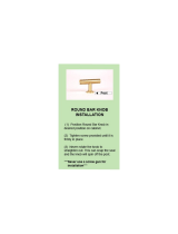
5. Handlebar Installation
Attach the Handlebar (6) onto the Handlebar Post (24) with one Handlebar Adjustment
Knob Plate (25) and M10 Adjustment Knob (13). Turn the M10 Adjustment Knob (13) in
a clockwise direction to lock the Handlebar (6) in the suitable position.
Knob: Hardware:
ASSEMBLY
13
(13) Adjustment Knob M10
1 PC
(25) Handlebar Adjustment
Knob Plate
1 PC

6. Water Bottle Holder Installation
Attach the Water Bottle Holder (33) onto the Main Frame (18) with two M5x16 Bolts (34).
Tighten bolts with the Multi Hex Tool with Phillips Screwdriver provided.
Install the Water Bottle (32) into the Water Bottle Holder (33).
Hardware:
ASSEMBLY
14
Multi Hex Tool with Phillips
Screwdriver S13-14-15
Tool:
(34) Bolt M5x16
2 PCS

7. Foot Pedals Installation
The Cranks, Pedal Shafts, and Foot Pedals are marked “R” for Right and “L” for
Left.
Insert the pedal shaft of Left Foot Pedal (15) into threaded hole in the Left Crank (38).
Turn the pedal shaft by hand in the counter-clockwise direction until snug.
Note: DO NOT turn left foot pedal shaft in the clockwise direction, doing so will
strip the threads.
Tighten the pedal shaft of Left Foot Pedal (15) with the Multi Hex Tool with Phillips
Screwdriver provided.
Insert pedal shaft of Right Foot Pedal (35) into threaded hole in Right Crank (36). Turn
the pedal shaft by hand in the clockwise direction until snug. Tighten pedal shaft of
Right Foot Pedal (35) with the Multi Hex Tool with Phillips Screwdriver provided.
Note: DO NOT turn right foot pedal shaft in the counter-clockwise direction, doing
so will strip the threads.
ASSEMBLY
Multi Hex Tool with Phillips
Screwdriver S13-14-15
Tool:
15

8. Computer Installation
Attach the Computer Bracket (43) onto the Handlebar (6) with two M6x6 Bolts (41).
Tighten bolts with the Multi Hex Tool with Phillips Screwdriver provided.
Remove two M6x15 Bolts (44) from the back of the Computer (42). Remove bolts
with the Multi Hex Tool with Phillips Screwdriver provided.
Attach the Computer (42) onto the Computer Bracket (43) with two M6x15 Bolts (44)
that were removed. Tighten bolts with the Multi Hex Tool with Phillips Screwdriver
provided.
Connect the Hand Pulse Sensor Wires (28) and Extension Sensor Wire (45) to the
wires that come from the Computer (42).
Hardware:
16
ASSEMBLY
Multi Hex Tool with Phillips
Screwdriver S13-14-15
Tool:
(41) Bolt M6x6
2 PCS

BUTTON FUNCTIONS:
MODE: Press the "Mode" button to change modes and to confirm setup.
SET: Used to set the values for TIME, DISTANCE, CALORIES and PULSE.
You can hold the button to increase the value at a faster rate. (Only works while
machine is stopped.)
RESET: To clear the set-up value. Press RESET key and hold for 2 seconds to reset all
function figures.
RECOVERY: An after workout cool down function. Gives a 1 minute cool down. To
test heart rate recovery status.
COMPUTER FUNTIONS:
SCAN: Displays all functions in sequence every 6 seconds.
RPM: Displays total Revolutions Per Minute. The display will automatically switch
between RPM and SPEED every 6 seconds after starting exercise.
SPEED: Displays current speed.
TIME: You can press “SET” button to set target time between 0:00 to 99:00 minutes for
count down function.
It can be set up by the user or accumulated automatically for count up function.
DISTANCE: Your can press “SET” button to set target distance between 0:00 to 99:50
miles for count down function.
It can be set up by the user or accumulated automatically for count up function.
CALORIES: You can press “SET” button to set target calories between 0 to 9990
calories for count down function.
It can be set up by the user or accumulated automatically for count up function.
PULSE: Displays the user’s pulse. User may set the target pulse. When pulse value
reaches to the target, the computer will alarm with “Bi” sound.
COMPUTER
17

OPERATION PROCEDURE:
1. Installs 2 pieces of AAA batteries, then the screen will display as following “Drawing
A” with a “Bi” sound at the same time, then enter into the main menu as “Drawing B”.
2. Gives you access the setup mode for TIME, DISTANCE, CALORIES and TARGET
PULSE. When you are in each setup mode, for instance the time setup, when the
time value is blinking, you can press the "SET" button to adjust the number. Press
the "MODE" button to confirm and move to the next part of setup. The setup for
DISTANCE, CALORIES & TARGET PULSE is the same as for TIME.
3. With the signal has been transmitted into the monitor, the value of TIME, DISTANCE,
or CALORIES start to count up as Drawing C. When there is any one of functions
has been pre-set the target (TIME, DISTANCE or CALORIES), the function will be
counting down from the pre-set value to zero. Once the target is achieved to zero,
the monitor start to beep for 8 seconds, and the function will be counting up from
zero immediately if the training is still going.
4. In SCAN mode shown as “Drawing C”. All functions will display in sequence every
6 seconds.
Drawing A
Drawing B
Drawing C
18
COMPUTER

5. You can also press “MODE” button to select single function display except RPM
and SPEED function. The RPM and SPEED function will switch display.
6. RECOVERY:
The Pulse Recovery is for personal orientation and compares the approximate pulse
rate before and after training. You will notice that your fitness will improve with
regular exercise. The Pulse Recovery feature is to be used directly after your
workout. RECOVERY function is only valid when there’s a heart rate input
detected. To use this function:
1) Grip the handlebar hand pulse sensors with both your hands during exercise.
2) Press the RECOVERY button.
3) The time will countdown from 0:60 to 0 seconds, see Drawing D. Grip the
handlebar hand pulse sensors with both your hands.
4) Your personal fitness Pulse Recovery level will appear on the display. When
countdown is complete, the Pulse Recovery grade will be displayed, see Drawing
E. (F1 is the best, F6 is the worst.)
If the count down action to 0:00 is not completed and there is no pulse signal, the
count down action has to be done and shown F6.
Before time reaches to 0:00, user can press the RECOVERY button to go back to the
main menu.
NOTE:
If you stop training for 4 minutes, the main screen will turn off. You may press any
button to turn on the computer, the original value will retain.
HOW TO INSTALL THE BATTERIES:
1. Remove the battery cover on the back of the computer.
2. Place two "SIZE-AAA" batteries into the battery housing.
3. Insure batteries are correctly positioned and battery springs are in proper contact
with batteries.
4. Re-install the battery cover.
5. If the display is illegible or only partial segment appears, remove batteries and wait
15 seconds before reinstalling.
19
COMPUTER
Drawing D
Drawing E
/