Page is loading ...

TABLE OF CONTENTS
Safety Precautions ...............2~5
Maintenance ................................4
Precautions on Use......................5
Preparation ..........................6, 7
Name of Parts ..........................6, 7
Switch ..........................................7
Installation .........................8~14
Preparation and Check
before Installation ...................8, 9
Cooker Hood Installation ....10~13
Operation Check .......................14
Maintenance ......................14~16
Caution for Maintenance ............14
Detaching/Attaching
Cleaned Parts ........................15, 16
Cleaning ......................................16
Other Information .............17, 18
Specifications ..............................17
Circuit Diagram ..........................17
Troubleshooting..........................18
Service and Warranty..................18
Cooker Hood
Thank you very much for your purchase of our cooker hood.
Before installing/operating the cooker hood, please read
this Manual thoroughly.
To the sales shop/installer:
A�er installation, please
give this manual to the user
without fail.
Installation/Operation Manual
FR-MT1990V
(Ventilating Type)
(Recycling Type)
FR-MT1990R
Ventilating Type
Recycling Type
Keep this manual in a convenient place for future reference.

2
Safety Precautions
WARNING
Mounting work should be done by 2 persons minimum.
Mounting
cautioned
Read the following safety instructions before operating, and use the cooker hood properly and securely.
These instructions are for correct operation of the product to prevent any risk of hazards or damages inflicting on
you or others. The instructions are classified into 2 categories as "WARNING" and "CAUTION" depending on their
emergency and severity. Pay attention and strictly observe the instructions as they are critical for safety.
Safety Precautions
Never attempt to disassemble, repair, or modify.
Entrust them to the qualified technician, otherwise fire, electric shock, or abnormal
performance may occur.
Disassembly,
repair, or
modification
prohibited
The cooker hood is intended to be installed over a hob with up to four hob elements
or burners.
Less than
4 burners
Don’t connect to the power voltage other than 220V/230V/240V AC.
Fire or electric shock may result in.
Using
prohibited
Be sure to disconnect the power plug from the wall outlet, or switch off the breaker
when care and maintenance. Also, don’t handle the power plug or breaker with
wet hand.
Electric shock or injury may result in.
Disconnect
the plug
When dust accumulated on the blades of the power plug or on their roots, wipe off
well.
Fire may result in.
Wipe off dust
When there may be a gas leak in your gas hob, don’t switch on or off the cooker hood.
Gas explosion may result in.
Operation
prohibited
Don’t spray water on the electric parts.
Fire or electric shock may result in.
Spraying
water
prohibited
Choose a mounting location where sufficient air flow is maintained.
CO poisoning may result if not ventilated adequately while using a natural vent type stove, etc.
Air supply
cautioned
Electric wiring must be made properly by the professional installer or personnel.
Incorrect wiring may be cause of electric leakage or fire.
Assembly
cautioned
WARNING
CAUTION
Alerts possible risk of
death
or serious injury
Alerts possible risk of
injury or
physical damage
, if not observed.
, if not observed.

3
Be sure to disconnect the power plug from the wall outlet, or switch off the breaker
when not using for a long time.
Insulation may be deteriorated, and fire or electric shock may result in.
Disconnect
by holding
the plug
Accessible parts may become hot when used with cooking appliances.
Don’t touch the filter or parts around it while cooking.
The filter or parts may drop, and burn or injury may result in.
Using
prohibited
Ensure that electric wiring is made safely according to the standard or
regulations related.
Incorrect wiring may result in fire or electrical shock.
Assemble the fan or component parts securely.
Injury by dropping may result in.
While disconnecting the power plug, hold the plug . Don’t pull the cord anyway.
The cord may be damaged, and fire or electric shock may result in.
Assembly
cautioned
Never use the product in a wet place such as bath room, etc. (Use a ventilation fan for
bath room.)
It may be cause of fire or failure if used.
CAUTION
There shall be adequate ventilation of the room when the cooker hood is used
at the same time as appliances burning gas or other fuels. (Not applicable to
appliances that only discharge the air back into the room.)
Air supply
cautioned
Mounting
cautioned
Mount the product securely a�er selecting a solid place.
Dropping may result in injury.
Improper
discharge
prohibited
The minimum distance between the wok pan support of the hob and the lowest
part of the cooker hood should be at least 750mm when the cooker hood is
located above the hob.
If the instructions for installation of the hob specify a greater distance, this has to
be taken into account.
The air must not be discharged into a flue which is used for exhausting fumes from
appliances burning gas or other fuels (not applicable to appliances that only
discharge the air back into the room).
WARNING
This appliance is not intended for use by person (including children) with reduced
physical, sensory or mental capabilities, or lack of experience and knowledge, unless
they have been given supervision or instruction concerning use of the appliance by
a person responsible for their safety.
Children should be supervised to ensure that they do not play with the appliance.
Supervision
requested
Exhaust adjustment must be ensured.
Ensure
adjustment
There is a fire risk if cleaning is not carried out in accordance with the instructions.
Clean
frequently
Do not flambé under the cooker hood.
Flambé
prohibited
Safety Precautions
Mounting
cautioned
Disconnect
the plug
Assembly
cautioned
Contact
prohibited

4
CAUTION
Caution
When the oil reaches one half of the oil tray, it must be cleaned to prevent overflow
and oil dripping during removal.
During installation, the hook and plastic expansion pipe (on the concrete wall) must
be matched with the product to prevent the product from falling.
In order to prevent the product from falling, the plastic expansion pipe used must be
equipped with a corresponding drill bit with a minimal gap between them.
The exhausting construction work should be carried out by the qualified person
in accordance to the related law and regulations.
Use attachment screws only.
If you fail to follow the instructions provided in this manual when installing other screws
or fixed equipment, it may cause an electrical hazard.
Contact FUJIOH or an agent when changing LED lamps in this product.
Prohibited
To avoid eye damage, do not look directly at the LED light while it is on.
If the power cord is damaged, it must be replaced by the manufacturer, its service agent
or similarly qualified persons in order to avoid a hazard.
Replace the
cord if it’s
damaged
Wear gloves
Be sure to wear gloves during care and maintenance.
Injury by the sharp edges or corners may result in.
Prohibited
Do not put anything on the cooker hood.
It may be cause of fire, failure, or injury by dropping.
Operation
prohibited
Switch off the cooker hood at once if the oil catches fire while cooking.
It’s dangerous if not switched off, as fire is built up.
Contact
prohibited
During operation, never insert fingers or other objects.
Failure or injury may result in.
Maintenance
Clean the cooker hood as many times as possible (especially, clean the filter once every month) as it
will become greasy. For a family size of 4 to 5 people and cooking twice a day, clean the filter once in
every two weeks.
If the cooker hood is le� unattended for a long time, much oil is accumulated and it will become
difficult to remove the hardened grease.
Safety Precautions
Caution
Caution
Caution
Mounting
cautioned
Mounting
cautioned

5
Operate the cooker hood without fail when using cooking wares.
Otherwise, it may be cause of the cooker hood damage or failure due to increased temperature.
Don’t use a gas range with nothing put on it.
The body of the cooker hood is heated, and it may cause trouble.
Prevent influence of direct wind from air conditioner.
Smoke capturing performance may be deteriorated if influenced. Especially, as the Induction
Heater (IH) provides nearly no ascending air current, it is easily influenced in open place.
When using with the Induction Heater (IH), smoke capturing performance may be
deteriorated by influence of cross wind. Also, the surface of the cooker hood may suffer
dew condensation if it is used in low temperature.
In this case, use the cooker hood a�er wiping off.
During operation, pay attention to sufficient air supply.
Provide adequate air intake slots on the wall opposite from the cooker hood, or open the door
of the room a little.
Otherwise, ventilation performance may be deteriorated, or abnormal noise/vibration may result in.
Separate gas heater more than 500mm from the cooker hood.
Since the surrounding of gas heater gets hotter, separate more than 500mm.
Never install the cooker hood above gas heater. If not, it may be cause of the cooker hood
damage or failure by increased temperature.
Do not use the cooker hood with its rectifier panel removed.
Smoke capturing performance may be deteriorated.
Precautions on Use
Safety Precautions

6
Preparation
Name of Parts
Preparation
Ventilating type
Recycling type
Main unit
LED
Fixing screw
Filter
Rectifier panel
Oil tray
Fan
Fan Guard
Duct Cover
Slide Duct Cover
Recycling Device
(Recycling type)
Duct Cover Fixing Bracket
(2 pieces)
Hanging Bracket

7
Preparation
List of included items
Main unit
Rectifier panel
Oil tray
Installation screw pack
Manual
Mounting the main unit
Main unit
Rectifier panel
Oil tray
Installation screw pack
Manual
Mounting the main unit
Installation screw pack list
ST5×50 Wood screw
Plastic expansion pipe
ST4.2×9.5 flat head screw
Li�ing the whole machine
Li�ing the whole machine
Li�ing the whole machine
Switch
Power button.........................ON/OFF
Low button.............................when the smoke is less or when desiring silent operation
Middle button.........................normal operation
High button.............................when there's much smoke or when desiring quick air exchange
Timer button ..........................3/6/9 minutes delay for shutdown of the whole machine under
working state
Lamp ON/OFF.........................ON/OFF of independently controlling the lamp
FR-MT1990V (Ventilating type)
Name
Usage
Quantity
1
1
1
1
1
1
2
FR-MT1990R(Recycling type)
4+(2)
7
7
4
1
1
1
1
1
1
1
2
1
1
1
1
Name
Usage
Quantity
Name
Usage
Quantity
Duct Cover
Duct Cover
Slide Duct Cover
Slide Duct Cover
Recycling Device
Hanging Bracket
Hanging Bracket
Mounting the slide duct cover/duct cover
Duct Cover Fixing Bracket
Duct Cover Fixing Bracket
Mounting the slide duct cover/duct cover
Mounting the main unit/slide duct cover/duct cover
Mounting the main unit/slide duct cover/duct cover/recycling unit
Recycling Device(Recycling type)
ST4×8 Cross recessed flat head screw

8
Installation
Preparation and Check before Installation
CAUTION
Checking mounting surface strength
The mounting surface should have sufficient strength enough to support the cooker hood.
Mount the cooker hood on a place durable to support the weight of the cooker hood.
In the case of boarded wall
If the thickness is more than 20mm, mount the cooker hood directly to the wall.
If the thickness is less than 20mm, embed a reinforcing board and mount the cooker hood to
this board.
In the case of a concrete/tile faced wall
Embed a reinforcing board in the wall in advance, or use a curl plug or the like.
Power plug
This product include a power plug. Be sure to use the wall outlet only for the cooker hood.
Checking accessory parts
Take out the main unit and accessory parts from the packing box, and check whether there is any shortage.
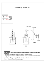
Installation
3. The air must not be discharged into a flue which is used for exhausting fumes from appliances burning
gas or other fuels (not applicable to appliances that only discharge the air back into the room).
1. Mount the cooker hood carefully and avoid contact with any metal parts (the lath in the wall or the
like) of the building.
2. Never embed the body of the cooker hood in the wall.Otherwise, electricity might leak in
the wall,which in any case flows to the body of the cooker hood.
4. The minimum distance between wok pan support of the hob and the lowest part of the cooker hood.
Should be at least 750mm while the cooker hood is located above the hob.
If the instructions for installation for the hob specify a greater distance, this has to be taken into
account.
5. Use a gas range having a narrower width than that of the cooker hood.
6. Avoid using the cooker hood with changes in the specification, for instance, with modifying the
switch.
7. Do not install the cooker hood in a wet area or in other wet rooms since it may result in electric
shock or damage.
8. Do not install the cooker hood at a place where its ambient temperature exceeds 40°C, otherwise it
may result in failure.
9. To protect your hands from injury, wear working gloves when installing the cooker hood.
10. If the power cord is damaged, it must be replaced by the manufacturer or its service agent or a
similarly qualified person in order to avoid a hazard.

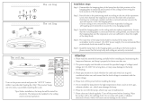
9
Installation
Confirmation of the installation location(Unit:mm)
Body mounting
hole(seven places)
FR-MT1990V
FR-MT1990R
600~1030(Ventilating type)
600~650(Recycling type)
≧750
80
80
Hanging Bracket
Duct Cover
Fixing Bracket
306
120
10.5
316
76
200
900
289
505
550
60
Power cord
97
91
187

Cooker Hood Installation
10
Installation
Installation method
1. Remove the fixing screw attached
to the front side of the filter.
Remove the filter.
3. Install the recycling device assembly
(for recycling type).
Secure the exhaust box assembly with
4 ST4×8 flat head screws.
2. Remove the fan guard from the
4 mounting screws attached to
the fan guard.
Use the appropriate accessories for installation (see page 7).
Note
4. 5 pieces of ST5×50 wood screws
(installation size on page 9)
The duct cover fixing bracket and
the hanging bracket are fixed on the wall.
If you use a plastic expansion pipe, use a
Ø10mm drill bit to drill holes in the wall.
The hole diameter is Ø10mm and the depth
is 55mm or more.
Filter
Fixing Screw
ST4×8
Flat head screws
Recycling Device
ST5×50 wood screws
Duct Cover
Fixing Bracket
Hanging
Bracket
Fan Guard
Mounting Screws
Note
Recycling type

11
Installation
5. Please ensure that breaker is in "off"
position,and then,plug power supply
into the socket.
Note
When you connect power plug,
please be sure to turn off the breaker
of switchboard.
6. Assemble the duct cover fixing bracket
and 2 ST4.2×9.5 flat head flat head screws
to duct cover.
Duct Cover
Fixing Bracket
ST4.2×9.5
Flat head screws
Duct Cover
7. Insert slide duct cover from the top
into the gap between duct cover fixing
bracket by laterally bending towards
the inside of duct cover.
Duct Cover
Slide Duct Cover
Duct Cover
Fixing Bracket
For the Ventilating type, as shown in the right figure,
cut the flexible tube duct to the required length and
shrink it before installing the flexible tube duct .
(Applicable to ventilating type)
Flexible Tube Duct
Taping with non-flammable
materials
(Aluminum tape,etc.)
8. Assemble the combination of duct cover
and slide duct cover to the main unit.
While assembling please, fit the lower part
of the duct cover combination unit first
while supporting the upper part to avoid
the falling of combination unit.
Slide Duct Cover
Duct Cover
Main unit
The longer the exhaust pipe, the worse the ventilation
performance. Straighten the exhaust pipe as much as
possible. The more turns, the worse the ventilation performance.
80
15
70
90
Power supply
installation location
Ventilating type
Note

12
Preparation
11. Fix slide duct cover and duct cover
fixing bracket with 2 ST4.2×9.5
flat head screws.
Slide Duct Cover
ST4.2×9.5
Flat Head Screws
13. Fix the fan guard with 4 fixing
mounting screws.
Mounting Screws
Fan Guard
9. Hook the main unit to the hanging bracket.
10.Fix 2 ST5×50wood screws in the hole
on the back of the main unit.
Main unit
ST5×50Wood screws
Flexible Tube Duct
Slide Duct Cover
Duct Cover
Ventilating type
Recycling type
12. For the ventilating type, please lengthen the
telescopic flexible tube duct and connect it to the
exhaust pipe connected to the outside with
a flame retardant metal tape.
Flexible Tube Duct
Exhaust Pipe
As shown in the figure to the right,
the ventilating type is equipped with
a flexible tube duct and then it is
mounted on the wall. (See page 11)
If the exhaust pipe has been installed
from the ceiling or the product height
is 750 mm or less, you can remove
the duct cover fixing bracket.
Note

13
16. Install the oil tray.
A.Align two feet of the oil tray with the
hole on the rectifier panel and insert
the oil tray into the hole,the direction
is shown in the right figure.
B.Push the oil tray into the slot.
Note:When removing the oil tray,push
one side out of the slot,and then push
the other side out of the slot.
15. Install the rectifier panel.
A. Put the rectifier panel on two rear hooking
brackets of the main unit.
B. Turn the rectifier panel horizontally, align it
with the le� and right ball catchers,and
push it forward towards the main unit.
Note: Ensure that the ball catchers in the
rectifier panel is completely clamped in
the clamp anchor. If it is not installed in
place, there may be a risk of falling.
Installation
14. Secure the filter with a fixing screw.
Hooking Bracket
Filter
Fixing Screw
Rectifier Panel
Ball Catch

14
Installation
1) Please install the oil tray matched with the product.
2) Turn on a breaker and check operation.
•
Check that the fan rotates normally at all speeds during operation.
•
Check that there are no abnormal sound or vibration.
Operation Check
Caution for Maintenance
Maintenance
Clean the cooker hood as many times as possible (especially, clean the filter once every month)
as it will become greasy. For a family size of 4 to 5 people and cooking twice a day,clean the
filter once in every two weeks. If the cooker hood is le� unattended for a long time,much oil is
accumulated and it will become difficult to remove the hardened grease.
• Before cleaning the cooker hood, be sure to disconnect the power plug from the receptacle,
or turn off the breaker.
• For safety, always wear a pair of rubber gloves while cleaning the filter, etc.
• Especially, be careful to prevent electric parts such as the motor, switch, connectors or the
like from coming into contact with water.
• Do not spray liquid or any types of detergent to the electric parts. It can cause trouble.
• Do not use solvents such as thinner, benzine, polishing powder or the like for cleaning the
painted surfaces, facing plates, etc. as these parts may become lusterless or scored.
• Do not wash parts with a hard brush or the like while cleaning as it can cause damage to the
product..
Power supply
Insert the power plug into the wall socket (220V/230V/240V AC).
Maintenance

15
Attaching
Rectifier Panel
Detaching
Hold the rectifier panel with two hands on both sides,
slightly pull it out to loosen the front end,then turn down
the rectifier panel to take it out of the cooker hood.
Note
Make sure that the rectifier panel is fixed securely.
It may be a cause of dropping if not fixed firmly.
Note
In order not to drop the rectifier panel, hold it by both
hands securely. If dropped, it may be a cause of injury,
flaw or warp of parts, etc.
Hold the rectifier panel with both hands, hang the end
of it into the hooking bracket,align the front end with the clamp
anchor and push it to the end,and ensure that the
rectifier panel is fully clamped in the ball catch.
Install all parts using the opposite procedure as that for removing the parts.
Oil Tray
Detaching/Attaching Cleaned Parts
Note
The oil tray may be filled with oil, so be careful when removing it.
When removing the oil tray,be sure to hold
the rectifier panel by hand to avoid accidental falling
off and causing injury.
Note
If the oil tray is not installed properly, it may result in oil dripping,
injury by dropping, etc.
Attaching
Hold the oil tray,insert the oil tray foot into the oil tray
hole,then push it completely to the end.
Detaching
Hold the rectifier panel with the le� hand,hold and pull
the oil tray with the right hand(first pull one side of the oil
tray out of the clamp,then pull the other side out of the
clamp in accordance to the convenience.)
Maintenance
Hooking Bracket
Ball Catch
Rectifier panel

16
Attaching
Note
Be sure to hold the filter with hand when removing it.
Otherwise, it may drop and result in injury.
Filter
Put the end of the filter into the hook,put the
filter into the groove smoothly,and tighten the
fixing screw.
Detaching
Hold the filter and remove the fixing screw at the
front of the filter.
Cleaning
Fan
As for cleaning of the fan, please consult FUJIOH/Agent.
Hood body /Duct Cover/Fan Guard
When cleaning, use a neutral detergent and so� cloth.
Do not use an organic solvent. A�er cleaning, wipe the hood well with a wet cloth dipped
in water to remove any remaining detergent, and finally thoroughly wipe any moisture off
using a dry cloth.
Note
When cleaning the rectifier panel, perform it on a flat surface in order not to deform it.
Oil tray/Rectifier panel/Filter
When cleaning, use a neutral detergent and so� cloth.
Do not use an organic solvent. A�er cleaning, wash off with water to remove all remaining
detergent,and finally thoroughly wipe any moisture off using a dry cloth.
Maintenance
fixing screw
Filter

Other information
Specifications
FR-MT1990V(Ventilating type)
Rated voltage
(V)
Speed
Frequency
(Hz)
Power consumption
(W)
Air flow
(㎥/h)
Sound
(dB)
220
230
240
Hi
Med
Low
Hi
Hi
Med
Med
Low
Low
50
50
50
195
146
106
211
158
114
226
170
121
570
410
255
600
440
270
620
465
285
50
42
32
51
44
34
52
45
35
*With 2×1.5W=3W Watts for lamp
FR-MT1990R(Recycling type)
Rated voltage
(V)
Speed
Frequency
(Hz)
Power consumption
(W)
Air flow
(㎥/h)
Sound
(dB)
220
230
240
Hi
Med
Low
Hi
Hi
Med
Med
Low
Low
50
50
50
126
117
99
134
123
104
143
128
114
260
205
120
270
220
130
270
230
140
56
50
39
56
52
40
57
53
41
*With 2×1.5W=3W Watts for lamp
Square/Diameter:
33.2mm×120mm
Max Power Voltage Picture
Lamp Cap
ILCOSD code
1.5W
DC12V
Dss-1.5-s-33.2
/120
Circuit diagram
AC INPUT
17
Other information

Other information
5
years
Troubleshooting
Before request repairing services,please confirm whether there is the following situation again.
Symptom
Possible cause
Action
A�er pressing the Power
switch,the fan and the
lamp don't work.
The fan doesn't work.
The lighting doesn't
light up.
There exists abnormal
sound.
Inadequate suction
force.
High operating noise.
1.Brake of the switchboard is"off".
2.Power plug is pulled out.
3.Connector bad contact or is
disconnected.
1.Connector suffers poor contact or
connector is disconnected.
1.The filter is clogged with grease
and dirt.
2.Air supply is not sufficient.
3.The mounting screws of the fan
are loose.
1.Using of several filters in addition to
the original filter like non-woven filter.
2.The filter is dirty.
3.Insufficient air supply.
4.Smoke from cooking is blown away
by the air from the air conditioner and
window.
5.The exhaust pipe outlet is blocked.
1.Brake of the switchboard is"on".
2.Plug in the power plug.
3.Request repairing.
1.Request repairing.
1.Clean the filter.
2.Ensure sufficient air supply and open the
window or air inlet.
3.Request repairing.
1.Remove other filters except the original
one.
2.Clean the filter.
3.Open the window and the air inlet,
ensure sufficient air supply.
4.Prevent from being blown by the wind.
5.Request smoke repairing.
Service and warranty
When requesting a�er sales service:
If any abnormality occurs while the cooker hood is in operation,switch off the cooker hood,
check the following points:
1)Whether the fuse in the circuit breaker has been burnt out?
2)Whether the power plug is not in proper contact with the receptacle?
If not above,disconnect the power plug from the receptacle and consult the shop from which you
have purchased your cooker hood.
When consulting,inform the shop the type/model of cooker hood requiring repair and the
date of purchase.
The minimum retention period of performance parts for repairing the cooker hood is 5
years a�er termination of manufacturing of the cooker hood.
The performance parts refer to those parts which requires to maintain the functions of a cooker hood.
However the same kinds of repair parts or interchangeable parts will be supplied for 4 years therea�er.
If the functions can be maintained when repaired,we are willing to repair when ordered by you.
The parts used on the cooker hood are subject to partial change without prior notice owing to
improvement of performance.
18

Global Website
www.fujioh.com
FUJIOH INTERNATIONAL TRADING PTE.LTD.
Southeast Asia Regional Headquarters
130 Joo Seng Road #05-05 Singapore 368357
Tel:(65)6286 3286 Fax:(65)6285 3285
E-mail:[email protected]om.sg
Rev3 2020
/