Westinghouse 04201 User manual

Category
Power generators
Type
User manual
USER MANUAL
DIGITAL INVERTER GENERATORS
FOR MODELS:
iGen1200, iGen2000,
iGen2500, iPro2500
2 | Westinghouse Portable Power
DISCLAIMERS:
All information, illustrations and specications in this manual are based on the latest information available at
the time of publishing. The illustrations used in this manual are intended as representative reference views only.
Moreover, because of our continuous product improvement policy, we may modify information, illustrations and/or
specications to explain and/or exemplify a product, service or maintenance improvement. We reserve the right
to make any change at any time without notice. Some images may vary depending upon which model is shown.
ALL RIGHTS RESERVED:
No part of this publication may be reproduced or used in any form by any means – graphic, electronic or
mechanical, including photocopying, recording, taping or information storage and retrieval systems – without the
written permission of MWE Investments LLC.
DANGER
This manual contains important instructions for operating this generator. For your safety
and the safety of others, be sure to read this manual thoroughly before operating the
generator. Failure to properly follow all instructions and precautions can cause you and
others to be seriously hurt or killed.
California
Proposition 65 Warning
The engine exhaust from this product
contains chemicals known to the state
of California to cause cancer, birth
defects or other reproductive harm.
California
Proposition 65 Warning
Certain components in this product and its
related accessories contain chemicals
known to the state of California to cause
cancer, birth defects or other reproductive
harm. Wash hands after handling.
Model
Number
Running
Watts
Peak
Watts
Fuel
Tank
Size
(L/G)
Rated
Speed
(RPM)
Ignition
Type
Spark
plug
Engine
Disp (cc)
Stroke X
Bore
Oil
Capacity
(L) Oil Type THD
iGEN 1200 1000 1200 3.0/.8 5200 CDI A5RTC 54 40X43.5 0.35 10W30 <5%
iGEN 2000 1800 2000 4.5/1.2 5300 CDI E6RTC 80 49X43 0.35 10W30 <5%
iGEN 2500 2200 2500 3.8/1.0 5500 CDI E6RTC 98 52X46 0.35 10W30 <5%
iPRO 2500 2200 2500 3.8/1.0 5500 CDI E6RTC 98 52X46 0.35 10W30 <5%
iGen TECHNICAL SPECIFICATIONS
HAVE QUESTIONS?
Email us at service@wpowereq.com
or call 1-855-944-3571
Westinghouse Portable Power | 3
FOR YOUR RECORDS:
Date of Purchase:
Inverter Model Number:
Purchased from Store/Dealer:
Inverter Serial Number:
IMPORTANT: KEEP YOUR PURCHASE RECEIPT TO ENSURE TROUBLE-FREE WARRANTY
COVERAGE.
PRODUCT REGISTRATION
To ensure trouble-free warranty coverage, it is important you register your Westinghouse inverter.
You can register your generator by either:
1. Filling in the product registration form below and mailing to:
Product Registration
MWE Investments LLC
777 Manor Park Drive
Columbus, Ohio 43228
2. Registering your product Online at www.westinghouseportablepower.com/register-your-product/
To register your generator you will need to locate the following information:
WESTINGHOUSE PRODUCT REGISTRATION FORM
PERSONAL INFORMATION INVERTER INFORMATION
First Name: _______________________________________ Model Number: _____________________________________
Last Name: _______________________________________ Serial Number: ______________________________________
Street Address: ___________________________________ Date Purchased: ____________________________________
Street Address: ___________________________________ Purchased From: ____________________________________
City, State, ZIP: ____________________________________
Country: __________________________________________
Phone Number: ___________________________________
E-Mail: ___________________________________________
Model Info Decal located on side panel.
(See pages 7-8 for placement)
Serial Number which is located on
bottom of muer cover.
4 | Westinghouse Portable Power
TABLE OF CONTENTS
IGEN TECHNICAL SPECIFICATIONS .............2
PRODUCT REGISTRATION .....................3
For Your Records: ..........................3
Product Registration .......................3
Product Registration Form ...................3
SAFETY .....................................5
Safety Denitions ...........................5
Safety Symbol Denitions ....................5
General Safety Rules ........................6
Safety Labels and Decals ....................7
UNPACKING .................................8
FEATURES ..................................9
Basic Inverter Features iGen1200 ..............9
Control Panel Features iGen1200 ..............9
Basic Inverter Features iGen2000,
iGen2500 & iPro2500 ........................10
Control Panel Features iGen2000 ..............10
Control Panel Features iGen2500 ..............11
Control Panel Features iPro2500 ...............11
OPERATION .................................12
Powercord ................................13
Inverter Paralleling Operation .................13
Initial Oil Fill ...............................14
Adding/Checking Engine Fluids and Fuel ........15
Checking and/or Adding Engine Oil. . . . . . . . . . . . . 15
Adding Gasoline to the Fuel Tank ..............15
Starting the Inverter iGen1200 .................16
Starting iGen2000, iGen2500 & iPro2500 ........17
Using Eciency Mode .......................17
Resetting the Reset Breaker ..................17
Stopping the Inverter ........................17
MAINTENANCE ..............................18
Maintenance Schedule ......................18
Engine Oil Maintenance ......................19
Checking Engine Oil. . . . . . . . . . . . . . . . . . . . . . . . . 19
Adding Engine Oil ..........................19
Changing Engine Oil ........................20
Air Filter Maintenance .......................21
Cleaning the Air Filter ........................21
Draining the Float Bowl ......................22
Spark Plug Maintenance .....................22
Cleaning the Spark Arrestor ...................23
Checking and Adjusting Valve Lash. . . . . . . . . . . . . 23
Cleaning the Inverter ........................24
Storage ..................................24
TROUBLESHOOTING .........................25
EXPLODED AND ENGINE VIEWS ................26
iGen1200 Exploded View .....................26
iGen1200 Engine View .......................27
iGen2000 Exploded View .....................28
iGen2000 Engine View .......................29
iGen2500 Exploded View .....................30
IGen2500 Engine View .......................31
Westinghouse Portable Power | 5
SAFETY DEFINITIONS
The words DANGER, WARNING, CAUTION and
NOTICE are used throughout this manual to highlight
important information. Be certain that the meanings of
these alerts are known to all who work on or near the
equipment.
This safety alert symbol appears
with most safety statements. It
means attention, become alert, your
safety is involved! Please read and
abide by the message that follows
the safety alerts symbol.
DANGER
Indicates a hazardous situation which, if not
avoided, will result in death or serious injury.
WARNING
Indicates a hazardous situation which, if not
avoided, could result in death or serious injury.
CAUTION
Indicates a hazardous situation which, if not
avoided, could result in minor or moderate injury.
NOTICE
Indicates a situation which can cause damage
to the generator, personal property and/or the
environment, or cause the equipment to operate
improperly.
NOTE: Indicates a procedure, practice or condition
that should be followed in order for the
generator to function in the manner
intended.
SAFETY
SAFETY SYMBOL DEFINITIONS
6 | Westinghouse Portable Power
DANGER
Never use the inverter in a location that is wet or damp. Never expose the inverter to rain, snow,
water spray or standing water while in use. Protect the inverter from all hazardous weather
conditions. Moisture or ice can cause a short circuit or other malfunction in the electrical circuit.
Never operate the inverter in an enclosed area. Engine exhaust contains carbon monoxide. Only
operate the inverter outside and away from windows, doors and vents.
WARNING
Voltage produced by the inverter could result in death or serious injury.
Never operate the inverter in rain or a ood plain unless proper precautions are taken to avoid
being subject to rain or a ood.
Never use worn or damaged extension cords.
Always have a licensed electrician connect the inverter to the utility circuit.
Never touch an operating inverter if the inverter is wet or if you have wet hands.
Never operate the inverter in highly conductive areas such as around metal decking or steel works.
Always use grounded extension cords. Always use three-wire or double-insulated power tools.
Never touch live terminals or bare wires while the inverter is operating.
Be sure the inverter is properly grounded before operating.
WARNING
Gasoline and gasoline vapors are extremely ammable and explosive under certain conditions.
Always refuel the generator outdoors, in a well-ventilated area.
Never remove the fuel cap with the engine running.
Never refuel the inverter while the engine is running. Always turn engine o and allow the
generator to cool before refueling.
Only ll fuel tank with gasoline.
Keep sparks, open ames or other form of ignition (such as match, cigarette, static electric
source) away when refueling.
Never overll the fuel tank. Leave room for fuel to expand. Overlling the fuel tank can result in a
sudden overow of gasoline and result in spilled gasoline coming in contact with HOT surfaces.
Spilled fuel can ignite. If fuel is spilled on the inverter, wipe up any spills immediately. Dispose of
rag properly. Allow area of spilled fuel to dry before operating the inverter.
Wear eye protection while refueling.
Never use gasoline as a cleaning agent.
Store any containers containing gasoline in a well-ventilated area, away from any combustibles or
source of ignition.
Check for fuel leaks after refueling. Never operate the engine if a fuel leak is discovered.
WARNING
Never operate the inverter if powered items overheat,
electrical output drops, there is sparking, ames or smoke
coming from the inverter, or if the receptacles are damaged.
Never use the inverter to power medical support equipment.
Always remove any tools or other service equipment used
during maintenance from the inverter before operating.
NOTICE
Never modify the inverter.
Never operate the inverter if it
vibrates at high levels, if engine
speed changes greatly or if the
engine misres often.
Always disconnect tools or
appliances from the
inverter before starting.
GENERAL SAFETY RULES
SAFETY
Westinghouse Portable Power | 7
SAFETY
SAFETY LABELS AND DECALS IGEN1200
1
2
5
3 4
1
3
2
4
5
8 | Westinghouse Portable Power
SAFETY
SAFETY LABELS AND DECALS IGEN2000, IGEN2500 AND IPRO2500
1 2
3
5
4
CAUTION
Always have assistance when lifting
the inverter. The inverter is heavy;
lifting it could cause bodily harm.
Avoid cutting on or near staples
to prevent personal injury.
UNPACKING
5
2
3
4
1
Tools required – box cutter or similar device.
1. Carefully cut the packing tape on top of the carton.
2. Remove tool kit, oil and funnel and save for later.
3. Carefully cut two sides of the carton to
remove the inverter.
WHAT COMES IN THE BOX
Tool Bag (1)
Screw Driver (1)
Owner Manual (1)
Warranty Information (1)
Quick Start Guide (1)
Funnel (1)
Bottle of 10W-30 Oil (1)
Westinghouse Portable Power | 9
Control Panel: Contains the reset breaker,
outlets and warning lights.
Spark Plug Access Cover: Remove the cover
to service the spark plug.
Recoil Handle: Pull to start the engine.
Engine/Fuel Control Switch: Turns the engine
and the fuel on and o.
120-Volt, 20-Amp Duplex Outlet (NEMA 5-20R): The
outlet is capable of carrying a maximum of 20 amps.
USB Duplex: 5V DC that come with 1 and 2.1 amp rating.
Reset Breaker: If the inverter is overloaded, the reset breaker
will trip. The engine will continue to run, but there will be no
output from the inverter. Unplug the devices and reduce the
load. Push in the reset breaker to reset it.
Eciency Mode Switch: When turned to the ON position, the
engine will sense the load needed and run at a slower RPM to
save fuel.
Ground Terminal: The ground terminal is used to externally
ground the inverter.
Output Ready LED: Indicates the inverter is ready to be used.
Overload LED: Indicates that the inverter is overloaded.
Low Oil LED: Indicates low oil level.
FEATURES
BASIC INVERTER FEATURES IGEN1200
CONTROL PANEL FEATURES IGEN1200
1
1
5
6
7
2
2
3
3
4
4
5
6
7
8
Fuel Cap and Vent: Open the vent to run the
engine and close the vent when the engine is o.
Engine Service Panel: Remove the panel to
access the engine for maintenance.
Muer and Spark Arrestor: Avoid contact
until the engine is cooled down. The spark
arrestor prevents sparks from exiting the
muer. It must be removed for servicing.
7
1
2
3
4
5
6
1
2
3
4
5
7 8
6
10 | Westinghouse Portable Power
FEATURES
BASIC INVERTER FEATURES IGEN2000, IGEN2500 AND IPRO2500
Fuel Cap and Vent: Open the vent to run the
engine and close the vent when the engine is o.
Control Panel: Contains the reset breaker,
outlets and warning lights.
Spark Plug Access Cover: Remove the cover
to service the spark plug.
Recoil Handle: Pull to start the engine.
Engine/Fuel Control Switch: Turns the engine
and the fuel on and o.
1
5
6
7
8
9
2
3
4
2
1
3
4
5
6
7
8
9
CONTROL PANEL FEATURES IGEN2000
120-Volt, 20-Amp Duplex Outlet (NEMA 5-20R):
The outlet is capable of carrying a maximum of
20 amps.
USB Duplex: 5V DC that come in 1 amps and
2.1 amps.
Reset Breaker: If the inverter is overloaded, the
reset breaker will trip. The engine will continue to
run, but there will be no output from the inverter.
Unplug the devices and reduce the load. Push in
the reset breaker to reset it.
Eciency Mode Switch: When turned to the ON
position, the engine will sense the load needed
and run at a slower RPM to save fuel.
Ground Terminal: The ground terminal is used to
externally ground the inverter.
Low Oil LED: Indicates low oil level.
1
2
3
4
5
6
7
8
9
Engine Service Panel: Remove the panel to access
the engine for maintenance.
Muer and Spark Arrestor: Avoid contact until the
engine is cooled down. The spark arrestor prevents
sparks from exiting the muer. It must be removed for
servicing.
Engine Cooling Vents: Helps move airow in unit to
regulate engine temperatures.
Recoil Handle Protective Cover: Prevents pull cord
wire from damaging inverter body.
Overload LED: Indicates that the inverter is overloaded.
Output Ready LED: Indicates the inverter is ready to
be used.
Fuel Control and Choke Switch: Turn position to
CHOKE to start the engine, and turn to RUN position
once the engine is running. Switch to OFF to stop inverter.
1
2
3
9
4
5
7 8
6
Westinghouse Portable Power | 11
FEATURES
CONTROL PANEL FEATURES IGEN2500
120-Volt, 20-Amp Duplex Outlet (NEMA 5-20R): The
outlet is capable of carrying a maximum of 20 amps.
USB Duplex: 5V DC that come in 1 amps and 2.1 amps.
Reset Breaker: If the inverter is overloaded, the reset breaker
will trip. The engine will continue to run, but there will be no
output from the inverter. Unplug the devices and reduce the
load. Push in the reset breaker to reset it.
Eciency Mode Switch: When turned to the ON position, the
engine will sense the load needed and run at a slower RPM to
save fuel.
Ground Terminal: The ground terminal is used to externally
ground the inverter.
Fuel Control and Choke Switch: Turn position to CHOKE to
start the engine, and turn to RUN position once the engine is
running. Switch to OFF to stop inverter.
LED Data Center: Indicates low oil, overload and output ready.
Displays fuel level, power output percentage, run time, and
lifetime run hours.
1
2
3
4
5
6
7
1
2
3
6
4
7
5
CONTROL PANEL FEATURES IPRO2500
120-Volt, 20-Amp Duplex GFCI Outlet: The
outlet is GFCI with a Reset and Test button. It is capable of
carrying a maximum of 20 amps.
USB Duplex: 5V DC that come in 1 amps and 2.1 amps.
Reset Breaker: If the inverter is overloaded, the reset breaker
will trip. The engine will continue to run, but there will be no
output from the inverter. Unplug the devices and reduce the
load. Push in the reset breaker to reset it.
Eciency Mode Switch: When turned to the ON position, the
engine will sense the load needed and run at a slower RPM to
save fuel.
Ground Terminal: The ground terminal is used to externally
ground the inverter.
Low Oil LED: Indicates low oil level.
Overload LED: Indicates that the inverter is overloaded.
Output Ready LED: Indicates the inverter is ready to be used.
Fuel Control and Choke Switch: Turn position to CHOKE to
start the engine, and turn to RUN position once the engine is
running. Switch to OFF to stop inverter.
1
2
3
4
5
6
7
8
9
1
2
3
9
4
5
7 8
6
12 | Westinghouse Portable Power
Weather – Never operate your inverter outdoors during
rain, snow or any combination of weather conditions that
could lead to moisture collecting on, in or around the
generator.
Dry SurfaceAlways operate the inverter on a dry
surface free of any moisture.
No Connected LoadsMake sure the inverter has no
connected loads before starting it. To ensure there are no
connected loads, unplug any electrical extension cords
that are plugged into the control panel receptacles.
NOTICE
Starting the inverter with loads already applied to
it could result in damage to any appliance being
powered o the inverter during the brief start-up
period.
Grounding the iGen Inverters
Consult with your local municipalities for your
grounding codes.
Grounding the iPro2500
When using the iPRO2500 equipped with the GFCI
receptacle a ground rod may be required to be connected
to the control panel ground stud to prevent nuisance
tripping of the GFCI receptacle.
WARNING
Be sure the inverter is properly
connected to earth ground before
operating.
BEFORE STARTING THE INVERTER
BEFORE STARTING THE INVERTER,
REVIEW SAFETY SECTION STARTING
ON PAGE 5.
Location Selection – Before starting the inverter, avoid
exhaust and location hazards by verifying:
You have selected a location to operate the inverter
that is outdoors and well ventilated.
You have selected a location with a level and solid
surface on which to place the inverter.
You have selected a location that is at least 6 feet
(1.8 m) away from any building, other equipment or
combustible material.
If the inverter is located close to a building, make
sure it is not located near any windows, doors and/
or vents.
WARNING
Always operate the inverter on a level
surface. Placing the inverter on non
level surfaces can cause the inverter
to tip over, causing fuel and oil to spill.
Spilled fuel can ignite if it comes in
contact with an ignition source such
as a very hot surface.
NOTICE
Only operate the inverter on a solid, level surface.
Operating the inverter on a surface with loose
material such as sand or grass clippings can cause
debris to be ingested by the inverter that could:
• Block cooling vents
• Block air intake system
OPERATION
Westinghouse Portable Power | 13
POWERCORD
Using Extension Cords
Westinghouse Portable Power assumes no responsibility for the content within this table. The use of this table is the
responsibility of the user only. This table is intended for reference only. The results produced by using this table are
not guaranteed to be correct or applicable in all situations as the type and construction of cords are highly variable.
Always check with local regulations and a licensed electrician prior to installing or connecting an electrical appliance
INVERTER PARALLELING OPERATION
DANGER
Never connect the paralleling cord
to the inverters with the inverters
running. The inverters must not be
running and both the paralleling cord
switches must be o when connecting
the cords.
WARNING
Do not attempt to parallel the
Westinghouse inverter with any other
manufacturers’ inverters. Do not use
the paralleling cord for any application
other than inverter paralleling. Do not
use this cord on other manufacturers’
inverters.
Always ensure that both ends of
the paralleling cord are switched o
before connecting the inverters.
INVERTER PARALLELING OPERATION
1. Using only the Westinghouse paralleling cord (Part
No. 260041) with both cord switches set to OFF
(O), connect one male plug to one inverter and
connect the remaining plug into the other inverter.
Either of the receptacles on the inverters can be
used.
2. Start one of the inverters and wait until the ready
light is on.
3. Turn both cord switches to ON (I).
4. Start the remaining inverter; wait until the ready
light is on before connecting the load.
5. When power is present, a light will illuminate in the
three-prong plug that is plugged into the inverter.
6. To stop the inverters, unplug all connected loads,
turn both cord switches to OFF (O) and unplug the
cord on each inverter.
7. If during operation the inverters’ output is stopped
due to overloading, reduce the connected load by
unplugging appliances, and then push the reset
button and restart the inverter. When the ready light
is on, the load can be reconnected.
OPERATION
14 | Westinghouse Portable Power
iGen2000, iGen2500 & iPro2500
1. Loosen the screw and remove the engine oil ll/
drain plug service panel to access the oil ll/drain
plug (see Figure 3)
Figure 3: Engine Service Panel
2. Clean the area around the oil ll/drain plug and
remove plug (See Figure 4).
Figure 4: Oil Fill/Drain Plug
3. Using the supplied funnel and oil, pour the entire
bottle of oil into the engine (see Figure 4).
Figure 5: Oil Funnel
4. Do not overll, if oil level is too high, oil will drain
out through the ll plug. See correct oil level in
Figure 2.
INITIAL OIL FILL
BEFORE ADDING ENGINE OIL, REVIEW
SAFETY SECTION STARTING ON PAGE 5.
NOTICE
Engine oil must be added when the inverter is on a
at, level surface, or an inaccurate reading may result.
Do not overll. If the engine is overlled with oil, it can
cause serious engine damage.
iGen1200
1. Loosen the screw and remove the engine service
panel to access the oil ll/drain plug (see Figure 1).
Figure 1: iGen1200 Engine Service Panel
2. Clean area around oil ll/drain plug and remove
plug.
3. Using the supplied funnel and oil, pour the entire
bottle of oil into the engine. See correct oil level in
Figure 2 below.
Figure 2: Engine Oil Correct Level
4. Do not overll, if oil level is too high, oil will drain
out through the ll plug.
OPERATION
Westinghouse Portable Power | 15
ADDING/CHECKING ENGINE
FLUIDS AND FUEL
BEFORE ADDING/CHECKING ENGINE
FLUIDS AND FUEL, REVIEW SAFETY
SECTION STARTING ON PAGE 5.
DANGER
Filling the fuel tank with gasoline while
the inverter is running can cause
gasoline to leak and come in contact
with hot surfaces that can ignite the
gasoline.
Before starting the inverter, always check the level of:
Engine oil
Gasoline in the fuel tank
Once the inverter is started and the engine gets warm,
it is not safe to add gasoline to the fuel tank or engine
oil to the engine while the engine is running or the en-
gine and muer are hot.
CHECKING AND / OR ADDING ENGINE OIL
WARNING
Internal pressure can build in the
engine crankcase while the engine
is running. Removing the oil ll plug/
dipstick while the engine is hot can
cause extremely hot oil to spray out of
the crankcase and can severely
burn skin. Allow engine oil to cool for
several minutes before removing the
oil ll plug/dipstick.
The unit as shipped does not contain oil in the engine.
You must add engine oil before starting the inverter
for the rst time. See Initial Oil Fill on page 14 for
instructions on checking engine oil level and the
procedure for adding engine oil.
NOTICE
The engine does not contain engine oil as shipped.
Attempting to start the engine without adding
engine oil will permanently damage internal engine
components.
The engine is equipped with a low oil shutdown
switch. If the oil level becomes low, the engine may
shut down and not start until the oil is lled to the
proper level.
The owner of the inverter is responsible to ensure the
proper oil level is maintained during the operation of
the generator. Failure to maintain the proper oil level
can result in engine damage.
ADDING GASOLINE TO THE FUEL TANK
WARNING
Never refuel the inverter while the
engine is running.
Always turn the engine o and allow
the inverter to cool before refueling.
CAUTION
Avoid prolonged skin contact with
gasoline. Avoid prolonged breathing of
gasoline vapors.
Required Gasoline – Only use gasoline that meets the
following requirements:
Unleaded gasoline only
Gasoline with maximum 10% ethanol added
Gasoline with an 87 octane rating or higher
Filling the Fuel Tank – Follow the steps below to ll the
fuel tank:
1. Shut o the inverter.
2. Allow the inverter to cool down so all surface areas
of the muer and engine are cool to the touch.
3. Move the inverter to a at surface.
4. Clean area around the fuel cap.
5. Remove the fuel cap by rotating counterclockwise.
NOTICE
Do not overll the fuel tank. Spilled fuel will damage
some plastic parts.
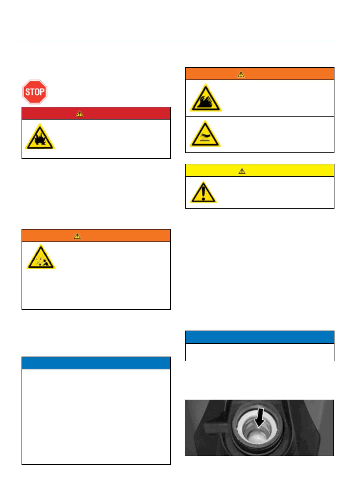
6. Slowly add gasoline into the fuel tank. Be very care-
ful not to overll the tank. The gasoline level should
NOT be higher than the red ring (see Figure 6).
7. Install the fuel cap by rotating clockwise.
Figure 6: Maximum Gasoline Fill Level
OPERATION
16 | Westinghouse Portable Power
STARTING THE INVERTER
BEFORE STARTING THE INVERTER,
REVIEW SAFETY SECTION STARTING
ON PAGE 5.
For proper starting and operation of the inverter,
make sure you review the inverter features and their
descriptions starting on page 9.
NOTE: For the iGen1200, upon initial start-up or
when out of fuel, ll the inverter to the full level. If
there is only a half tank of fuel, the fuel system will
need to be primed. To prime the fuel system, turn
the engine/fuel control switch to the ON position
and pull the recoil handle 5 to 6 times.
Before attempting to start the inverter, verify the
following:
The engine is lled with engine oil (see Figure 2:
Engine Oil Correct Level on page 14).
The inverter is situated in a proper location (see
Location Selection on page 12).
The inverter is on a dry surface (see Weather and Dry
Surface on page 12).
All loads are disconnected from the inverter (see No
Connected Loads on page 12).
The inverter is properly grounded (see Grounding the
Inverter on page 12)
DANGER
Never use the inverter in a location
that is wet or damp. Never expose
the inverter to rain, snow, water
spray or standing water while in use.
Protect the inverter from all hazardous
weather conditions. Moisture or ice
can cause a short circuit or other
malfunction in the electrical circuit.
Never operate the inverter in an
enclosed area. Engine exhaust
contains carbon monoxide. Only
operate the inverter outside and away
from windows, doors and vents.
Starting iGen1200
1. Turn the fuel tank vent to the ON position (see
Figure 7).
Figure 7: Turn Fuel Vent to ON
2. Turn the engine/fuel control switch to the ON
position (see Figure 8).
Figure 8: Turn Engine/Fuel Switch to ON Position
3. Move the choke lever to the CHOKE position (see
Figure 9).
Figure 9: Move Choke Lever to CHOKE
4. Firmly grasp and pull the recoil handle slowly until
you feel increased resistance. At this point, apply
a rapid pull while pulling out from the inverter (see
Figure 10).
Figure 10: Pull the Recoil Handle out from Inverter
5. As the engine starts and stabilizes, gradually push
the choke lever back in to the RUN position.
OPERATION
Westinghouse Portable Power | 17
Starting iGen2000, iGen2500 & iPro2500
1. Turn the fuel tank vent to the ON position (see
Figure 11).
Figure 11: Turn Fuel Vent to ON
2. Turn the engine/fuel control switch to the CHOKE
position (see Figure 12).
Figure 12: Turn Engine/Fuel Switch to CHOKE Position
3. Firmly grasp and pull the recoil handle slowly until
you feel increased resistance. At this point, apply
a rapid pull while pulling out from the inverter (see
Figure 13).
Figure 13: Pull the Recoil Handle out from Inverter
4. As the engine starts and stabilizes, turn the choke
switch back in to the RUN position (see Figure 14).
Figure 14: Turn Engine/Fuel Switch to RUN
USING EFFICIENCY MODE
The inverter is equipped with an eciency mode switch
to minimize fuel consumption. In eciency mode, the
inverter will sense the load and adjust the engine RPM
to the current load requirements. Eciency mode
should be used only after the inverter has been warmed
up to operating temperature.
1. To turn on the eciency mode, press the switch to
the ON position).
2. If no load is present, the inverter RPM will drop
down to an idle speed.
3. As a load is applied, the inverter will sense the load
and engine RPM will increase according to the load
applied.
4. To run the inverter at maximum power and RPM,
press the eciency mode switch to the OFF
position.
RESETTING THE RESET BREAKER
The inverter will trip the breaker and automatically
disconnect from the load when the controls sense a
predetermined overload condition. The inverter engine
will continue to run, but there will not be any electrical
output.
1. Turn o all devices and unplug them from the
inverter.
2. Determine the wattage required from the devices
being powered by the inverter. Make sure the
wattage required does not exceed the maximum
output of the inverter.
3. Press in the reset breaker to reset it.
4. Plug the devices in to the inverter.
5. Turn on the devices as needed.
STOPPING THE INVERTER
Normal Operation
During normal operation, use the following steps to
stop your inverter:
6. Remove any connected loads from the control
panel receptacles.
7. Allow the inverter to run at “no load” to reduce and
stabilize engine and alternator temperatures.
8. Move the engine control switch to the OFF position.
9. Turn the fuel tank vent to the OFF position.
During an Emergency
If there is an emergency and the inverter must be
stopped quickly, move the engine control switch to the
OFF position immediately.
OPERATION
18 | Westinghouse Portable Power
CAUTION
Avoid skin contact with engine oil or
gasoline. Prolonged skin contact with
engine oil or gasoline can be harmful.
Frequent and prolonged contact with
engine oil may cause skin cancer.
Take protective measures and wear
protective clothing and equipment.
Wash all exposed skin with soap and
water.
WARNING
Failure to perform periodic
maintenance or not following
maintenance procedures can cause
the inverter to malfunction and could
result in death or serious injury.
NOTICE
Periodic maintenance intervals vary depending on
inverter operating conditions. Operating the inverter
under severe conditions, such as sustained high-
load, high-temperature, or unusually wet or dusty
environments, will require more frequent periodic
maintenance. The intervals listed in the maintenance
schedule should be treated only as a general
guideline.
WARNING
Avoid accidentally starting the inverter
during maintenance by removing
the spark plug boot from the spark
plug. For electric start inverters, also
disconnect the battery cables from the
battery (disconnect the black negative
(-) cable rst) and place the cables
away from the battery posts to avoid
arcing.
Allow hot components to cool to
the touch prior to performing any
maintenance procedure.
Internal pressure can build in the
engine crankcase while the engine
is running. Removing the oil ll plug/
dipstick while the engine is hot can
cause extremely hot oil to spray out
of the crankcase and can severely
burn skin. Allow engine oil to cool for
several minutes before removing the
oil ll plug/dipstick.
Always perform maintenance in a well-
ventilated area. Gasoline fuel and fuel
vapors are extremely ammable and
can ignite under certain conditions.
MAINTENANCE
BEFORE PERFORMING MAINTENANCE ON THE INVERTER, REVIEW THE
SAFETY SECTION STARTING ON PAGE 5, AS WELL AS THE FOLLOWING
SAFETY MESSAGES.
TABLE 1: MAINTENANCE SCHEDULE - OWNER PERFORMED
Maintenance Item
Before Every
Use
After First 20
Hours or First
Month of Use
After 50 Hours
of Use or Every
6 Months
After 100 Hour
of Use or Every
6 Months
After 300 Hours
of Use or Every
Year
Engine Oil
Check Level Change Change - -
Cooling Features
Check/Clean - - - -
Air Filter
Check - Clean* - Replace
Spark Plug
- - - Check/Clean Replace
Spark Arrestor
- - - Check/Clean -
*Service more frequently if operating in dry and dusty conditions
Following the maintenance schedule is important to keep the inverter in good operating condition. The following is a
summary of maintenance items by periodic maintenance intervals.
Westinghouse Portable Power | 19
Oil Fill/Drain Plug iGen2000, iGen2500 & iPro2500
7. Check oil level: When checking the engine oil,
remove the oil ll/ drain plug.
The oil level is acceptable if oil is visible at the
bottom of the threads of the oil ll plug.
If oil level is low, add to the correct level using
the supplied oil ll bottle. Do not overll the oil
crankcase.
NOTICE
Engine oil must always be checked and added when
the inverter is on a at, level surface, or an inaccurate
reading may result, causing serious engine damage.
ADDING ENGINE OIL
8. Always operate or maintain the inverter on a at
surface.
9. Stop engine if running.
10. Let engine sit and cool for several minutes (allow
crankcase pressure to equalize).
11. Remove the engine service panel to gain access to
the oil ll/drain plug.
12. Thoroughly clean around the oil ll/drain plug.
13. Remove the oil ll/drain plug.
14. Select the proper engine oil as specied in Figure
14.
15. Using the supplied oil funnel, slowly add engine oil
to the engine. Stop frequently to check the oil level
and avoid overlling.
ENGINE OIL MAINTENANCE
Engine Oil Specication
1. Only use the engine oil specied in Figure 14.
2. Only use 4-stroke/cycle engine oil. NEVER USE
2-STROKE/CYCLE OIL. Synthetic oil is an
acceptable substitute for conventional oil.
Figure 14: Recommended Oil
CHECKING ENGINE OIL
NOTICE
Always maintain proper engine oil level. Failure to
maintain proper engine oil level could result in severe
damage to the engine and/or shorten the life of the
engine.
Always use the specied engine oil. Failure to use the
specied engine oil can cause accelerated wear and/
or shorten the life of the engine.
Engine oil level should be checked before every use.
1. Always operate or maintain the inverter on a at
surface.
2. Stop engine if running.
3. Let engine sit and cool for several minutes (allow
crankcase pressure to equalize).
4. Remove the engine service panel to access the oil
ll/drain plug.
5. With a damp rag, clean around the oil ll/drain plug.
6. Remove the oil ll/drain plug.
Oil Fill/Drain Plug iGen1200
MAINTENANCE
20 | Westinghouse Portable Power
Drain Oil iGen2000, iGen2500 & iPro2500
7. Allow oil to completely drain.
8. Fill crankcase with oil following the steps outlined in
Adding Engine Oil on page 19
9. Dispose of used engine oil properly.
NOTICE
Never dispose of used engine oil by dumping the
oil into a sewer, on the ground, or into groundwater
or waterways. Always be environmentally
responsible. Follow the guidelines of the EPA or
other governmental agencies for proper disposal
of hazardous materials. Consult local authorities or
reclamation facility.
Oil Fill/Drain Funnel iGen1200
Oil Fill/Drain Funnel iGen2000, iGen2500 & iPro2500
1. Continue to add oil until the oil is at the correct level
(see Figure 2 on page 14).
CHANGING ENGINE OIL
1. Stop the engine.
2. Let engine sit and cool for several minutes (allow
crankcase pressure to equalize).
3. Remove the engine service panel to gain access to
the oil ll/drain plug.
4. Place oil pan (or suitable container) under the oil ll/
drain plug.
5. With a damp rag, thoroughly clean around the oil
ll/drain plug.
6. Tilt the inverter so the oil drains down the through
into the container.
Drain Oil iGen1200
MAINTENANCE
1 / 1

Westinghouse 04201 User manual

Category
Power generators
Type
User manual

Ask a question and I''ll find the answer in the document

Finding information in a document is now easier with AI

Ask the document