Danfoss VLT AQUA Drive FC 202 Installation guide

Type
Installation guide

This manual is also suitable for

MAKING MODERN LIVING POSSIBLE
VVLT
p
AQUA Drive
Cascade Controller Options MCO 101/102
Operating Instructions
www.danfoss.com/drives
*MI38C402*
130R0345 MI38C402 Rev. 2012-08-21
Safety
WARNING
HIGH VOLTAGE
Frequency converters contain high voltage when
connected to AC mains input power. Qualified personnel
only should perform installation, start up, and
maintenance. Failure to perform installation, start up,
and maintenance by qualified personnel could result in
death or serious injury.
WARNING
UNINTENDED START
When the frequency converter is connected to AC mains,
the motor may start at any time. The frequency
converter, motor, and any driven equipment must be in
operational readiness. Failure to be in operational
readiness when the frequency converter is connected to
AC mains could result in death, serious injury,
equipment, or property damage.
WARNING
DISCHARGE TIME
Frequency converters contain DC-link capacitors that can
remain charged even when the frequency converter is
not powered. To avoid electrical hazards, disconnect AC
mains, any permanent magnet type motors, and any
remote DC-link power supplies, including battery back-
ups, UPS, and DC-link connections to other frequency
converters. Wait for the capacitors to fully discharge
before performing any service or repair work. The
amount of wait time is listed in the Discharge Time table.
Failure to wait the specified time after power has been
removed before doing service or repair could result in
death or serious injury.
Voltage
[V]
Minimum Waiting Time (Minutes)
4 15 20 30 40
200-240 0.25-3.7
kW
5.5-45 kW
380-480 0.37-7.5
kW
11-90 kW 110-250
kW
315-1000
kW
525-600 0.75-7.5
kW
11-90 kW
525-690 11-37 kW 45-400
kW
450-1200
kW
1400 kW
High voltage may be present even when the warning
LED display lights are off.
Discharge Time
Symbols
The following symbols are used in this manual.
WARNING
Indicates a potentially hazardous situation which could
result in death or serious injury.
CAUTION
Indicates a potentially hazardous situation which can
result in minor or moderate injury. It can also be used to
alert against unsafe practices.
CAUTION
Indicates a situation that could result in equipment or
property-damage-only accidents.
NOTICE
Indicates highlighted information to regard with
attention to avoid mistakes or operate equipment at less
than optimal performance.
Approvals
NOTICE
The T7 (525-690 V) frequency converters are not certified
for UL.
Safety
VLT
®
AQUA Drive MCO 101/MCO 102
MI38C402 - VLT
®
is a registered Danfoss trademark
Safety
VLT
®
AQUA Drive MCO 101/MCO 102
MI38C402 - VLT
®
is a registered Danfoss trademark
Contents
1 Introduction
3
1.1 Purpose of these Operating Instructions
3
1.1.1 Software Version 3
2 Application Types
5
2.1 Overview
5
2.2 Supported Configurations
5
2.2.1 Extension of Basic Cascade - Parameter Group 25** Control Mode 5
2.2.2 Master-Follower Configuration 7
2.2.3 Mixed Pump Configuration 8
2.2.3.1 Unequal Size Pump Configuration 8
2.2.3.2 Mixed Pump Configuration with Alternation 9
2.2.4 Using Soft Starters for Fixed Speed Pumps 10
2.3 Sleep Mode
10
2.3.1 Basic Cascade Controller 11
2.3.2 Master/Follower and Mixed Pump Configurations 11
3 Installation
12
3.1 Mechanical and Electrical Installation
12
3.1.1 Before Start 12
3.1.2 Extended Cascade Controller
MCO 101 12
3.1.3 Advanced Cascade Controller
MCO 102 14
4 Configuring the System
16
4.1 Configuring the Extended and Advanced Cascade Controller
16
4.1.1 Setting-up the Cascade Parameters 16
4.1.2 Configuration of Multiple Frequency Converters 16
4.1.3 Closed Loop Control 17
4.1.4 Staging/De-staging of Variable Speed Pumps 17
4.1.5 Staging/De-staging of Fixed Speed Pumps 17
4.2 Operation
18
4.2.1 Pump Status and Control 18
4.2.2 Manual Pump Control 18
4.2.3 Runtime Balancing 19
4.2.4 Pump Spin for Unused Pumps 19
4.2.5 Total Lifetime Hours 19
4.2.6 Alternation of the Lead Pump 19
4.2.7 Staging/De-staging in Mixed Pump Configurations 20
4.2.8 Override Staging/De-staging 20
Contents
VLT
®
AQUA Drive MCO 101/MCO 102
MI38C402 - VLT
®
is a registered Danfoss trademark 1
4.2.9 Minimum Speed De-staging 20
4.2.10 Fixed Speed only Operation 20
4.2.11 Flow Compensation for Applications with Cascade Controller 21
5 Parameter Descriptions
22
5.1 Cascade Controller Parameters
22
5.1.1 Cascade CTL Option, 27-** 24
5.1.3 Control & Status, 27-0* 25
5.1.4 Configuration, 27-1* 26
5.1.5 Bandwidth Settings, 27-2* 26
5.1.6 Staging Speed, 27-3* 28
5.1.7 Staging Settings, 27-4* 29
5.1.8 Alternation Settings, 27-5* 30
5.1.9 Digital Inputs, 27-6* 31
5.1.10 Connections, 27-7* 35
5.1.11 Readouts, 27-9* 36
5.2 Parameter Lists
37
5.2.1 25-** Cascade Controller 37
5.2.2 27-** Cascade CTL Option 38
6 Configuration Examples
41
6.1 Master/Follower
41
6.1.1 Basic Settings 41
6.1.2 Master Drive Settings 41
6.1.3 Follower Drive Settings 42
Index
43
Contents
VLT
®
AQUA Drive MCO 101/MCO 102
2 MI38C402 - VLT
®
is a registered Danfoss trademark
1 Introduction
1.1 Purpose of these Operating Instructions
The purpose of these operating instructions is to describe
the Danfoss Cascade Controller Options MCO 101 and
MCO 102.
The operating instructions contain information about:
Application types
Installation
Configuring the system
Parameters
Configuration examples
These operating instructions are intended for use by
qualified personnel. Read these operating instructions in
full in order to use the Cascade Controller Options safely
and professionally and pay particular attention to the
safety instructions and general warnings.
1.1.1
Software Version
Extended Cascade Controller Option for
VLT
®
AQUA Drive
Software version: 1.9x
Table 1.1 Software Version
NOTICE
MCO 101/102 is software supported from version 1.24
onwards.
1.1.2 Cascade Control
The Cascade Controller consists of an option board
containing 3 relays that is installed in option slot B. Once
options are installed the parameters needed to support the
Cascade Controller functions will be available through the
control panel in parameter group 27-**.
MCO 101 and 102 are add-on options extending the
supported number of pumps and the functionalities of the
built-in Cascade Controller in the VLT
®
AQUA Drive.
The following options for cascade control are available for
the VLT
®
AQUA Drive:
Built-in Basic Cascade Controller (standard
Cascade Controller)
MCO 101 (Extended Cascade Controller)
MCO 102 (Advanced Cascade Controller)
For further information, see 2 Application Types.
The Extended Cascade Controller can be used in two
different modes:
with the extended features controlled by
parameter group 27-**
to extend the number of available relays for the
Basic cascade controlled by parameter
group 25-**
With MCO 101, a total of 5 relays can be used for cascade
control and with MCO 102, a total of 8 pumps can be
controlled. The options are able to alternate the lead
pump with 2 relays per pump.
NOTICE
If MCO 102 is installed, the relay option MCB 105 can
extend the number of relays to 13.
Application
Cascade control is a common control system used to
control parallel pumps or fans in an energy efficient way.
The Cascade Controller option enables control of multiple
pumps configured in parallel by:
Automatically turning individual pumps on/off
Controlling the speed of the pumps
When using Cascade Controllers, the individual pumps are
automatically turned on (staged) and turned off (de-
staged) as needed in order to satisfy the required system
output for flow or pressure. The speed of pumps
connected to the VLT
®
AQUA Drive is also controlled to
provide a continuous range of system output.
Designated use
The Cascade Controller options are designed for pump
applications, however, it is also possible to use Cascade
Controllers in any application requiring multiple motors
configured in parallel.
Operating principle
The Cascade Controller software runs from a single
frequency converter with Cascade Controller option
(master drive). It controls a set of pumps, each controlled
Introduction
VLT
®
AQUA Drive MCO 101/MCO 102
MI38C402 - VLT
®
is a registered Danfoss trademark 3
1 1
by a frequency converter or connected to a contactor or a
soft starter.
Additional frequency converters in the system (follower
drives) do not need any Cascade Controller option card.
They are operated in open loop mode and receive their
speed reference from the master drive. Pumps connected
to follower drives are referred to as variable speed pumps.
Pumps connected to mains through a contactor or
through a soft starter are referred to as fixed speed
pumps.
Each pump, variable speed or fixed speed, is controlled by
a relay in the master drive.
The Cascade Controller options can control a mix of
variable speed and fixed speed pumps.
Other resources are available to understand advanced
functions and programming.
The VLT
®
AutomationDrive FC 302Operating
Instructions provide details on installation and
operation of the frequency converter.
The VLT
®
AutomationDrive FC 302 Programming
Guide provides greater detail on working with
parameters and many application examples.
The VLT
®
AutomationDrive FC 302 Design Guide
provides detailed capabilities and functionality to
design motor control systems.
Supplemental publications and manuals are
available from Danfoss.
See www.danfoss.com/BusinessAreas/DrivesSo-
lutions/Documentations/Technical
+Documentation.htm for listings.
Optional equipment may change some of the
procedures described. Reference the instructions
supplied with those options for specific
requirements. Contact the local Danfoss supplier
or visit the Danfoss website: www.danfoss.com/
BusinessAreas/DrivesSolutions/Documentations/
Technical+Documentation.htm, for downloads or
additional information.
Introduction
VLT
®
AQUA Drive MCO 101/MCO 102
4 MI38C402 - VLT
®
is a registered Danfoss trademark
11
2 Application Types
2.1 Overview
100% 100% 200% 200%
130BA594.12
Relay 1
Relay 2
Relay 10
Built-
in
1 VSP + 2 FSP
parameter group 25-** Cascade
Controller
- -
MCO
101
1 VSP + 5 FSP
parameter group 25-** Cascade
Controller
1 to 6 VSP + 1 to 5 FSP
(max. 6 pumps)
parameter group 27-** Cascade
CTL Option
6 VSP
parameter group 27-** Cascade
CTL Option
MCO
102
1 VSP + 8 FSP
parameter group 25-** Cascade
Controller
1 to 8 VSP + 1 to 7 FSP
(max. 8 pumps)
parameter group 27-** Cascade
CTL Option
8 VSP
parameter group 27-** Cascade
CTL Option
Table 2.1 Application Overview
VSP = Variable Speed Pump (directly connected to the frequency
converter)
FSP = Fixed Speed Pump (the motor could be connected via
contactor, soft starter or star/delta starter)
2.2 Supported Configurations
When setting-up the system, create a hardware configu-
ration, which communicates the number of connected
pumps and frequency converters to the master. The
necessary hardware is explained in the following hardware
configuration examples.
2.2.1
Extension of Basic Cascade -
Parameter Group 25** Control Mode
Use of the extended cascade option MCO 101 as an
extension of the built-in basic cascade in the frequency
converter
In applications already controlled by the built-in Cascade
Controller in parameter group 25-**, the option card can
be used to extend the numbers of relays for cascade
control. For instance if a new pump is added to the
system.
Enable the Basic Cascade Controller in 27-10 Cascade
Controller by selecting [3] Basic Cascade Ctrl. Refer to VLT
®
AQUA Drive Programming Guide for further programming
with parameter group 25-** settings.
Illustration 2.1 and Illustration 2.2 show the external wiring
needed for systems with alternating lead pump of 4
pumps using basic cascade and MCO 101 as relay
extension.
Application Types
VLT
®
AQUA Drive MCO 101/MCO 102
MI38C402 - VLT
®
is a registered Danfoss trademark 5
2 2
Illustration 2.1 Control Circuit Alternating Lead Pump (4 Pumps)
Illustration 2.2 Mains Circuit Alternating Lead Pump (4 Pumps)
The fixed speed pump configuration provides a cost
effective method for controlling up to 9 pumps. It is able
to control system output by controlling the number of
running pumps as well as the speed of the single variable
speed pump.
In this configuration the VLT
®
AQUA Drive controls one
variable speed pump and up to 8 fixed speed pumps. The
fixed speed pumps are staged and de-staged as needed
through contactors direct online. The variable speed pump
provides the finer level of control needed between the
stages.
The direct online pumps are staged or de-staged
depending on the feedback.
130BA592.12
Illustration 2.3 Fixed Speed Pump Configuration Example
Application Types
VLT
®
AQUA Drive MCO 101/MCO 102
6 MI38C402 - VLT
®
is a registered Danfoss trademark
22
NOTICE
If the pumps are not equal in size or if 2 relays per
pump are used, a Mixed Pump Configuration has to be
chosen.
For the configuration shown in Illustration 2.3, relay
selections in parameter group 27-7* Connections are as
follows
27-70.0 RELAY 1 [73] Pump 2 to Mains
27-70.1 RELAY 2 [74] Pump 3 to Mains
27-70.9 RELAY 10 [75] Pump 4 to Mains
27-70.10 RELAY 11 [0] Standard Relay
27-70.11 RELAY 12 [0] Standard Relay
NOTICE
Pressure fluctuations during staging/de-staging
transitions may occur and it may be less energy efficient
than the master-follower configurations.
2.2.2 Master-Follower Configuration
The master-follower cascade control mode offers the best
performance, the most precise control and maximum
energy savings. It controls multiple equal sized pumps in
parallel, running all pumps at the same speed and stages
the pumps on and off according to system requirements.
Compared to traditional cascade control the number of
running pumps is controlled by speed instead of feedback.
To obtain the highest energy saving the stage on and off
speed must be set correctly according to the system. In
this example terminal 27 of the master drive is used as
pulse output for the reference and the terminals 29 of the
follower drives are used as pulse input for this reference.
While the master drive is running in closed loop, the
followers are running in open loop. All follower drives are
connected to mains and motor in the same way as the
master drive.
Motor / Pump
1
Motor / Pump 2
Motor / Pump 3
Master
with
MCO 101/ 102 Follower 1 Follower 2
DI 18
DI 18 DI
29
DI 29
DO
27
R 1
R 2
100%
100%
100%
P
U / I
T 54
T 55
T 20
2
Pressure
Transmitter
0 - 10 V
0 - 20 mA or
4 - 20 mA
T 12
DI18
2
Start
130BD072.10
Illustration 2.4 Basic Wiring Principle (Example)
Application Types
VLT
®
AQUA Drive MCO 101/MCO 102
MI38C402 - VLT
®
is a registered Danfoss trademark 7
2 2
In this configuration each pump is controlled by a
frequency converter. All pumps and frequency converters
must be of the same size. Staging and de-staging decisions
are made based on the speed of the frequency converters.
The constant pressure is controlled by the master drive
operating in closed loop. The speed will be the same in all
running pumps with extended control.
In the Master/Follower mode, MCO 101 supports up to 6
pumps - MCO 102 up to 8 pumps. See 6.1 Master/Follower
for further details.
For the configuration shown Illustration 2.4 relay
selections in parameter group 27-7* Connections are as
follows:
27-70.0 RELAY 1 [1] Drive 2 Enable
27-70.1 RELAY 2 [2] Drive 3 Enable
27-70.9 RELAY 10 [0] Standard Relay
27-70.10 RELAY 11 [0] Standard Relay
27-70.11 RELAY 12 [0] Standard Relay
The system will automatically runtime balance all pumps
depending on the pump prioritization made in
27-16 Runtime Balancing. The master/follower system will
provide a certain level of redundancy. If the master drive
trips, it will continue to control the follower drives.
NOTICE
MCB 107 External 24 V DC power supply can be added
to increase the level of redundancy.
Relays set to [0] Std. Relay, can be used as general purpose
relays, controlled by parameter group 5-4* Relays.
2.2.3
Mixed Pump Configuration
This configuration combines some of the benefits of the
master follower configuration with some of the initial cost
savings of the fixed speed configuration. It is a good
choice when the extra capacity of the fixed pumps is rarely
needed.
The mixed pump configuration supports a mix of variable
speed pumps connected to frequency converters as well as
additional fixed speed pumps. The variable speed pumps
are staged on and de-staged first based on frequency
converter speed. The fixed speed pumps are then staged
on last and de-staged last based on the feedback pressure.
NOTICE
All variable speed pumps and frequency converters must
be the same size. Fixed speed pumps may be of different
sizes.
Illustration 2.5 Example
For this configuration relay selections in parameter
group 27-7* Connections are as follows:
27-70.0 RELAY 1 [1] Drive 2 Enable
27-70.1 RELAY 2 [74] Pump 3 to Mains
27-70.9 RELAY 10 [75] Pump 4 to Mains
27-70.10 RELAY 11 [0] Standard Relay
27-70.11 RELAY 12 [0] Standard Relay
2.2.3.1
Unequal Size Pump Configuration
The Unequal Size Pump configuration supports a limited
mix of fixed speed pumps in different sizes. It provides for
the largest range of system output with the smallest
number of pumps.
100% 100% 200% 200%
130BA594.12
Relay 1
Relay 2
Relay 10
Illustration 2.6 Example
For this configuration relay selections in parameter
group 27-7* Connections are as follows:
27-70.0 RELAY 1 [73] Pump 2 to Mains
27-70.1 RELAY 2 [74] Pump 3 to Mains
Application Types
VLT
®
AQUA Drive MCO 101/MCO 102
8 MI38C402 - VLT
®
is a registered Danfoss trademark
22
27-70.9 RELAY 10 [75] Pump 4 to Mains
27-70.10 RELAY 11 [0] Standard Relay
27-70.11 RELAY 12 [0] Standard Relay
For a configuration to be valid, it must be possible to
stage pumps in increments of 100% of the size of the
master drive’s variable speed pump. The variable speed
pump must control the output between the fixed speed
stages, see Illustration 2.7.
100% is defined as the maximum flow produced by the
pump connected to the master drive. The fixed speed
pumps must be multiples of this size.
NOTICE
Other valid configurations than the ones shown in
Table 2.2 are possible
Variable Speed Fixed Speed
100%
100% + 200% (see Illustration 2.7)
100% 100% + 200% + 200%
100% 100% + 100% + 300%
100% 100% + 100% + 300% + 300%
100% 100% + 200% + 400%
100% + 100% 200%
100% + 100% 200% + 200%
Table 2.2 Valid Configurations
100 %
100 %
100 %
100 %
100 %
100 %
200 % 200 %
C
1
100 %
200 %
300 %
400 %
2
3 4
130BD073.10
Illustration 2.7 Valid Configuration Example
NOTICE
Invalid configurations, like in Illustration 2.8, will still run
but will not stage on all pumps. This feature allows for
limited operation if a pump fails or is interlocked.
Variable
Speed
Fixed Speed
100% 200% (no control between 100%
and 200%)
100% 100% + 300% (no control between 200%
and 300%) (see Illustration 2.8)
100% 100% + 200% +
600%
(no control between 400%
and 600%)
Table 2.3 Invalid Configurations
130BD074.10
100 %
100 %
100 %
300 %
100 %
100 %
100 %
300 %
C
1
100 %
200 %
300 %
400 %
2 3 4
Illustration 2.8 Invalid Configuration Example
2.2.3.2
Mixed Pump Configuration with
Alternation
In this configuration the frequency converter alternates
between two pumps and controls the other as additional
fixed speed pump. The Cascade Controller attempts to
balance the running hours of the pumps.
Application Types
VLT
®
AQUA Drive MCO 101/MCO 102
MI38C402 - VLT
®
is a registered Danfoss trademark 9
2 2
Illustration 2.9 Example 1
As Illustration 2.9 the two pumps can be ether variable
speed or fixed speed with equal running hours.
For this configuration relay selections in parameter
group 27-7* Connections are as follows:
27-70.0 RELAY 1 [8] Pump 1 to Drive 1
27-70.1 RELAY 2 [16] Pump 2 to Drive 1
27-70.9 RELAY 10 [72] Pump 1 to Mains
27-70.10 RELAY 11 [73] Pump 2 to Mains
27-70.11 RELAY 12 [0] Standard Relay
Illustration 2.10 Example 2
With equal running hours for all three pumps, pump 1 and
2 can be either variable speed or fixed speed.
For this configuration relay selections in group 27-7*
Connections are as follows:
27-70.0 RELAY 1 [8] Pump 1 to Drive 1
27-70.1 RELAY 2 [16] Pump 2 to Drive 1
27-70.9 RELAY 10 [72] Pump 1 to Mains
27-70.10 RELAY 11 [73] Pump 2 to Mains
27-70.11 RELAY 12 [74] Pump 3 to Mains
Illustration 2.11 Example 3
Pumps 1 and 2 alternate each with 50% of the running
hours. The fixed speed pumps turned on and off as
needed with equal running time between them.
For this configuration relay selections in parameter
group 27-7* Connections are as follows:
27-70.0 RELAY 1 [8] Pump 1 to Drive 1
27-70.1 RELAY 2 [16] Pump 2 to Drive 1
27-70.9 RELAY 10 [74] Pump 3 to Mains
27-70.10 RELAY 11 [75] Pump 4 to Mains
27-70.11 RELAY 12 [76] Pump 5 to Mains
2.2.4
Using Soft Starters for Fixed Speed
Pumps
Soft Starters can be used in place of contactors for any
configuration using fixed speed pumps.
NOTICE
Mixing Soft Starters and contactors prevents control of
output pressure during staging and de-staging
transitions. Use of soft starters delays staging due to the
ramp time of the fixed speed pump.
2.3 Sleep Mode
If the load on the system allows for stop of the motor and
the load is monitored, the motor can be stopped by
activating the Sleep Mode function. This is not a normal
Stop command, but ramps the motor down to 0 RPM and
stops energizing the motor. When in Sleep Mode, certain
conditions are monitored to find out when load has been
applied to the system again.
Activate Sleep Mode either from the Low Power
Detection/Low Speed Detection or via an external signal
applied to one of the digital inputs (must be programmed
via parameter group 5-1* Digital Inputs). To use for
example an electro-mechanical flow switch to detect a no
Application Types
VLT
®
AQUA Drive MCO 101/MCO 102
10 MI38C402 - VLT
®
is a registered Danfoss trademark
22
flow condition and activate Sleep Mode, the action takes
place at raising edge of the external signal applied
(otherwise the frequency converter would never come out
of Sleep Mode again as the signal would be steady
connected).
Implementation and configuration of Sleep Mode depends
on the hardware configuration and the requirements.
2.3.1 Basic Cascade Controller
For Basic Cascade applications can be used and configured
exactly as it is described for single pump applications in
the Programming Guide. See descriptions of the parameter
groups 22-2*, 22-3* and 22-4* for further details.
Low Speed Detection as well as Low Power Detection in
combination with the timers for minimum run time,
minimum sleep time and the boost feature are supported.
The feedback from the pressure transducer is monitored
and when this pressure has dropped with a set percentage
below the normal set point for pressure (22-44 Wake-up
Ref./FB Difference), the motor will ramp up again and
pressure will be controlled for reaching the set value.
2.3.2
Master/Follower and Mixed Pump
Configurations
In multiple drive applications two different ways of the
Sleep Mode can be used.
It is possible to use the Sleep Mode as it is described for
the Basic Cascade Controller. For this configuration it is
essential, that the drive with the cascade controller option
is the last drive running after de-staging. This is achieved
by giving the connected pump the highest priority in the
parameters for runtime balancing ( e.g. by programming
the drive with the MCO 101 or the MCO 102 as ”Balanced
Priority 1” and all other drives/pumps as ”Balanced Priority
2” in 27-16 Runtime Balancing).
The other way makes usage of the Stage Off speeds in
parameter group 27-3* Staging Speed. This method requires
no special priority settings and therefore allows the
balancing of the running hours for all pumps.
In the following example the Sleep Mode in a Master/
Follower application is entered at 30 Hz.
Stage ON [Hz] Stage OFF [Hz]
Stage 1 48.5 (i.e. parameter 2732.1) 30 (i.e. parameter 2734.1)
Stage 2 48.5 (i.e. parameter 2732.2) 40 (i.e. parameter 2734.2)
Stage 3 48.5 (i.e. parameter 2732.3) 42 (i.e. parameter 2734.3)
Table 2.4
This mode is activated by programming the corresponding
speed in 27-33 Stage Off Speed [RPM] or 27-34 Stage Off
Speed [Hz] respectively.
The value for this speed has to be higher than the
minimum speed in 4-11 Motor Speed Low Limit [RPM] or
4-12 Motor Speed Low Limit [Hz].
The value for the override limit in 27-21 Override Limit
causes the frequency converter to wake-up again. The
value is entered as a % of the Maximum Reference as
programmed in 3-03 Maximum Reference.
See also 6 Configuration Examples for further details and
the entire description of the required programming steps
for a Master/Follower application.
Application Types
VLT
®
AQUA Drive MCO 101/MCO 102
MI38C402 - VLT
®
is a registered Danfoss trademark 11
2 2
3 Installation
3.1 Mechanical and Electrical Installation
3.1.1 Before Start
NOTICE
Before start, interrupt the power supply to the frequency
converter. Never install an option card into the
frequency converter during operation.
Voltage
[V]
Minimum Waiting Time (Minutes)
4 7 15 20
200-240 0.25-3.7 kW 5.5-45 kW
380-480 0.37-7.5 kW 11-90 kW
525-600 0.75-7.5 kW 11-90 kW
525-690 1.1-7.5 kW 11-90 kW
3x400 90-250 kW
3x400 110-315 kW
3x500 110-315 kW
3x500 132-355 kW
3x525 75-250 kW
3x525 90-315 kW
3x690 90-250 kW
3x690 110-315 kW
High voltage may be present even when the warning
LED display lights are off.
Table 3.1 Discharge Time
NOTICE
Export Control
From software version 6.72 the output of the frequency
converter is limited to 590 Hz. Software version 6x.xx is a
special software for export to countries where special
legislation for export control applies. In this version the
output of the frequency converter is also limited to 590
Hz, the difference from standard software is that it
cannot be flashed, i.e. neither downgraded nor
upgraded.
3.1.2 Extended Cascade Controller
MCO 101
The MCO 101 option includes 3 pieces of change-over
contacts and can be fitted into option slot B.
Max terminal load (AC)
240 V AC 2 A
Max terminal load (DC) 24 V DC 1 A
Min terminal load (DC) 5 V 10 mA
Max switching rate at rated load/min load
6 min
-1
/20 s
-1
Table 3.2 Electrical Data
130BA607.11
MCO 101
1
Illustration 3.1 Mounting of B Options
1 Dismount MCO 101 option to access RS-485 termination
(S801) or current/voltage switches (S201, S202)
Table 3.3
How to add the MCO 101 option:
1. Disconnect power to the frequency converter.
2. Disconnect power to the live part connections on
relay terminals.
3. Remove the LCP, the terminal cover and the
cradle from the FC 202.
4. Fit the MCO 101 option in slot B.
5. Connect the control cables and relief the cables
by the enclosed cable strips.
6. Fit the extended cradle and terminal cover.
7. Remount the LCP.
8. Connect power to the frequency converter.
Installation
VLT
®
AQUA Drive MCO 101/MCO 102
12 MI38C402 - VLT
®
is a registered Danfoss trademark
33
Relay 10
NC NCNC
Relay 12Relay 11
1 2 3 12
130BA606.10
754 6 8 9 10 11
Illustration 3.2 Usage of Connections
130BA177.10
8-9mm
2mm
Illustration 3.3 Mounting of Cables
WARNING
Do not combine low voltage parts and PELV systems (see
Illustration 3.4.
1 1 1
1 102 3 4 5 6 7 8 9 1211
2 2 3
1 1 1
1 102 3 4 5 6 7 8 9 1211
3 3 3
1 1 1
1 102 3 4 5 6 7 8 9 1211
2 2
2
130BA176.11
Illustration 3.4 Incorrect and Correct Relay Wiring
1 NC
2 Live part
3 PELV
Table 3.4 Legend to Correct Relay Wiring
Installation
VLT
®
AQUA Drive MCO 101/MCO 102
MI38C402 - VLT
®
is a registered Danfoss trademark 13
3 3
3.1.3 Advanced Cascade Controller
MCO 102
The VLT Advanced Cascade Control Card MCO 102 option
is exclusively intended for use in option slot C1. The
mounting position of C1 options is shown in
Illustration 3.5.
Max terminal load (AC) 240 V AC 2 A
Max terminal load (DC) 24 V DC 1 A
Min terminal load (DC) 5 V 10 mA
Max switching rate at rated load/min load
6 min
-1
/20 s
-1
Table 3.5 Electrical Data, MCO 102
Tools required
Some items are needed for the installation of a C option
mounting kit (depending on the enclosure):
Type Description Ordering number
Options
MCF 105 Mounting Kit frame size A2
and A3 (40 mm for one C
Option)
130B7530
MCF 105 Mounting Kit Frame size A5 130B7532
MCF 105 Mounting Kit Frame size B,
C, D, E , F1 and F3 (Except
B3)
130B7533
MCF 105 Mounting Kit frame size B3
(40 mm for one C Option)
130B1413
Accessory Bag
MCO 102 Accessory Bag 130B0152
Table 3.6 Ordering Numbers for Mounting Kits and Accessory Bag
Illustration 3.5 Enclosure A2, A3 (and B3) 40 mm (only one C option)
Installation
VLT
®
AQUA Drive MCO 101/MCO 102
14 MI38C402 - VLT
®
is a registered Danfoss trademark
33
DC
DC
130BA945.10
Illustration 3.6 Enclosures B (except B3) and C
How to add the MCO 102 option
1. Disconnect power.
2. Disconnect power to the live part connections on
relay terminals.
3. Remove the LCP, the terminal cover and the
cradle from the FC 202.
4. Fit the MCO 102 option in slot C1.
5. Connect the control cables and relief the cables
by the enclosed cable strips.
6. Fit the extended cradle and terminal cover.
7. Remount the LCP.
8. Connect power to the frequency converter.
Wiring the Terminals
130BB025.11
Illustration 3.7 Advanced Cascade Controller MCO 102
Terminal Connections, 8 Relays
130BB026.11
Illustration 3.8 Advanced Cascade Controller MCO 102
Terminal Connections to the 7 Digital Inputs and Access to
the Internal 24 V DC
Installation
VLT
®
AQUA Drive MCO 101/MCO 102
MI38C402 - VLT
®
is a registered Danfoss trademark 15
3 3
4 Configuring the System
4.1 Configuring the Extended and
Advanced Cascade Controller
The Extended- and Advanced Cascade Controller can be
quickly configured using many of the default parameters.
For more information about application types and on how
to use advanced features of the Cascade Controller
options, see also 2 Application Types.
NOTICE
To avoid a misconfiguration, check the settings even if
the parameters have their default values.
4.1.1 Setting-up the Cascade Parameters
Configure the Cascade Controller as follows:
1. Select values for the parameters in parameter
group 27-1* Configuration.
Parameter Description
27-10 Cascade Controller can be used to enable or disable
the Extended Cascade Controller. The mixed pump
selection is the general selection for the Cascade
Controller. If using one frequency converter per
pump the master-follower configuration can be
selected reducing the number of parameters needed
to setup the system.
27-11 Set number of frequency converters
27-12 Number of pumps - will default to the number of
frequency converters.
27-14 Pump capacity for each pump (Indexed Parameter) -
If all pumps are the same size the default values
shall be used. To adjust: first choose pump, press
[OK] and adjust the capacity.
27-16 Runtime balancing for each pump (Indexed
Parameter) - If the system should equally balance
the running hours between the pumps then use the
default values.
27-17 Motor Starters - All fixed speed pumps must be the
same.
27-18 Spin time for unused pumps - Depends on the size
of the pumps.
Table 4.1
2.
Define relays in parameter group 27-7*
Connections
Assign one relay for each follower drive in the
system
Assign the relays for the fixed speed pumps.
If it is necessary to have a single frequency
converter alternate between two pumps, then
assign additional relays.
NOTICE
Any unused relays will be available for other functions
through the parameter group 5-4* Relays.
4.1.2 Configuration of Multiple Frequency
Converters
If more than one frequency converter is used with the
Cascade Controller the master drive sets the frequency for
all frequency converters via a digital signal.
DO
Pin 27
DI
DI
Pin 29
Pin 29
DO
Pin 27
DI
DI
Pin 29
Pin 29
Illustration 4.1 Multiple Frequency Converters
NOTICE
All frequency converters always run at the same speed.
1.
Set basic cascade parameters, see 4.1.1 Setting-up
the Cascade Parameters
2.
Set 5-01 Terminal 27 Mode to [1] Output,
5-30 Terminal 27 Digital Output to [55] Pulse
output and 5-60 Terminal 27 Pulse Output Variable
to [116] Cascade ref.
3. Set each follower drive to open loop, set
1-00 Configuration Mode to [0] Open Loop and
3-15 Reference 1 Source to selection [7] Pulse input
29 and 5-13 Terminal 29 Digital Input to [32] Pulse
input.
Configuring the System
VLT
®
AQUA Drive MCO 101/MCO 102
16 MI38C402 - VLT
®
is a registered Danfoss trademark
44
NOTICE
3-41 Ramp 1 Ramp Up Time and 3-42 Ramp 1 Ramp Down
Time must be the same for the master drive and for all
follower drives in the system.
4. Set the ramps fast enough to enable the PID
controller to maintain control of the system.
4.1.3 Closed Loop Control
The master drive is the primary controller for the system. It
monitors the output pressure, adjusts the speed of the
frequency converters and decides when to add or remove
stages.
To perform this function:
1. setup the master drive closed loop mode with a
feedback sensor connected to an analog input of
the frequency converter.
2. setup the PID controller of the master drive to
match the needs of the installation.
For further information on setting up the PID parameters,
see the VLT
®
AQUA Drive Programming Guide. See also
6.1 Master/Follower.
4.1.4
Staging/De-staging of Variable Speed
Pumps
Staging occurs when the speed of the frequency converter
has reached the value in 27-31 Stage On Speed [RPM]
(27-32 Stage On Speed [Hz]). At this speed the system
pressure is still maintained but the pumps start to operate
outside of their peak efficiency points. Staging on an
additional pump will lower the speed of all running pumps
and provide a more energy efficient operation.
In master-follower configurations and mixed pump config-
urations the variable speed pumps are staged and de-
staged based on the speed of the frequency converters.
De-staging occurs when the speed of the frequency
converters drops below the value in 27-33 Stage Off Speed
[RPM] (27-34 Stage Off Speed [Hz]). At this speed the system
pressure is still maintained but the pumps are beginning
to operate below their peak efficiency points. De-staging a
pump will cause the speed of the frequency converters to
increase into a more energy efficient range.
27-31 Stage On Speed [RPM] (27-32 Stage On Speed [Hz]) and
27-33 Stage Off Speed [RPM] (27-34 Stage Off Speed [Hz]) are
installation dependent. These parameters are indexed
parameters with one set of entries for each pump stage.
The stage on and de-stage off speed can be auto tuned
during automation or set manually. If Auto-tune is enabled
the system will start operation using default settings or the
pre settings done by the user in 27-31 Stage On Speed
[RPM] (27-32 Stage On Speed [Hz]) and 27-33 Stage Off
Speed [RPM] (27-34 Stage Off Speed [Hz]) before enabling
the auto-tune.
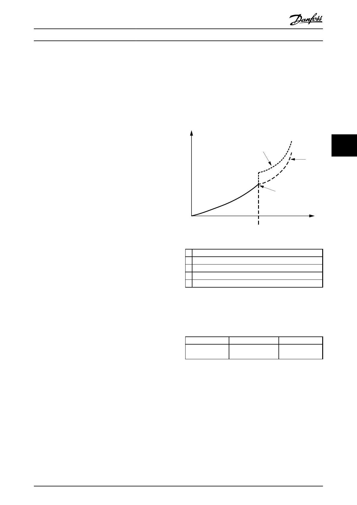
The tuning ensures optimum energy efficiency of the
system. See Illustration 4.2.
P
tot
A
B
C
t
1
2
130BB024.11
Illustration 4.2
1 1 pump running
2 2 pumps running
A Incorrect stage on speed adjustment
B Correct stage on speed adjustment
C Stage on speed pump 2
Table 4.2
During operation the system monitors the actual energy
consumption and optimises every time a stage or de-stage
takes place.
Parameter Range Default
27-30 Auto Tune
Staging Speeds
{[0] Disabled, [1]
Enabled}
[1] Enabled
Table 4.3
4.1.5
Staging/De-staging of Fixed Speed
Pumps
Fixed speed pumps are staged based or de-staged based
on system pressure.
To avoid rapid turning on and off of pumps, define an
acceptable range of system pressure along with a period
of time the pressure is allowed to be outside of this band
before staging or de-staging occurs. Set the values
through:
Configuring the System
VLT
®
AQUA Drive MCO 101/MCO 102
MI38C402 - VLT
®
is a registered Danfoss trademark 17
4 4
  • Page 1 1
  • Page 2 2
  • Page 3 3
  • Page 4 4
  • Page 5 5
  • Page 6 6
  • Page 7 7
  • Page 8 8
  • Page 9 9
  • Page 10 10
  • Page 11 11
  • Page 12 12
  • Page 13 13
  • Page 14 14
  • Page 15 15
  • Page 16 16
  • Page 17 17
  • Page 18 18
  • Page 19 19
  • Page 20 20
  • Page 21 21
  • Page 22 22
  • Page 23 23
  • Page 24 24
  • Page 25 25
  • Page 26 26
  • Page 27 27
  • Page 28 28
  • Page 29 29
  • Page 30 30
  • Page 31 31
  • Page 32 32
  • Page 33 33
  • Page 34 34
  • Page 35 35
  • Page 36 36
  • Page 37 37
  • Page 38 38
  • Page 39 39
  • Page 40 40
  • Page 41 41
  • Page 42 42
  • Page 43 43
  • Page 44 44
  • Page 45 45
  • Page 46 46
  • Page 47 47
  • Page 48 48
  • Page 49 49

Danfoss VLT AQUA Drive FC 202 Installation guide

Type
Installation guide
This manual is also suitable for

Ask a question and I''ll find the answer in the document

Finding information in a document is now easier with AI