Gladiator GAJG36FDYG Installation guide
- Category
- AV equipment stands
- Type
- Installation guide
This manual is also suitable for

PREMIER JUMBO CABINET
Assembly Instructions
ARMARIO GIGANTE DE
ALTA CALIDAD
Instrucciones de ensamblaje
GRANDE ARMOIRE
(PREMIER JUMBO)
Instructions d'assemblage
TABLE OF CONTENTS/ÍNDICE/TABLE DES MATIÈRES
CABINET/LOCKER SAFETY ........................ 2
PARTS ........................................................... 2
ASSEMBLY INSTRUCTIONS........................ 3
INSTALLATION INSTRUCTIONS................. 6
WARRANTY ................................................... 7
SEGURIDAD DEL ARMARIO .......................8
PIEZAS ............................................................8
INSTRUCCIONES DE ENSAMBLAJE ..........9
INSTRUCCIONES DE INSTALACIÓN........ 12
GARANTÍA ................................................... 13
SÉCURITÉ DE L’ARMOIRE.........................14
PIÈCES..........................................................14
INSTRUCTIONS D'ASSEMBLAGE .............15
INSTRUCTIONS D'INSTALLATION............18
GARANTIE ....................................................19
W10130911C
IT'S TIME TO RETHINK THE GARAGE.
®
ES TIEMPO DE VOLVER A PENSAR EN EL GARAGE.™
LE GARAGE REPENSÉ.™

2
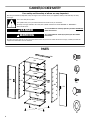
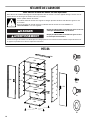
CABINET/LOCKER SAFETY
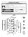
PARTS
F1
F2
F3c
F7
F8
You can be killed or seriously injured if you don't immediately
You
can be killed or seriously injured if you don't
follow
All safety messages will tell you what the potential hazard is, tell you how to reduce the chance of injury, and tell you what can
happen if the instructions are not followed.
Your safety and the safety of others are very important.
We have provided many important safety messages in this manual and on your appliance. Always read and obey all safety
messages.
This is the safety alert symbol.
This symbol alerts you to potential hazards that can kill or hurt you and others.
All safety messages will follow the safety alert symbol and either the word “DANGER” or “WARNING.”
These words mean:
follow instructions.
instructions.
DANGER
WARNING
P2
P5mr
P5ml
P5mr
P3
P6
P7
P1
P1
AAA
BBB
DDD
EEE
CCC
P4
P8
P8
P8

3
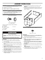
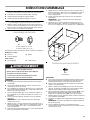
ASSEMBLY INSTRUCTIONS
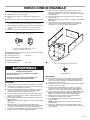
Cabinet Use Requirements
■ Intended for use in a garage.
■ Maximum weight limit is 50 lbs (22.7 kg) for each shelf.
■ Maximum weight limit is 300 lbs (136 kg) for the cabinet.
Unpack Cabinet Parts
1. Remove and verify the contents. Contents include a hex key, a
key, and the parts and fasteners shown in “Parts.”
2. Dispose of/recycle all packaging materials.
Assemble Cabinet
Gather the required tools before starting installation.
Tools Needed:
Tools Supplied:
IMPORTANT:
■ Two people may be required to complete the assembly.
■ As you assemble the cabinet, make sure the edges with the
holes are facing up.
■ If you are assembling the cabinet on the floor, fasten the eight
front corner bolts, two at each corner, after you stand the cabinet
upright.
1. Place side panel (P1) on a flat, firm surface so that the edge with
the holes is facing up as shown.
2. Insert the cabinet top (P2) between the edges of side panel (P1).
NOTE: Make sure the edges with the holes are facing up.
3. Align the holes and attach the top (P2) to side panel (P1) using
Hex-head bolts (F1) and the three ⁵⁄₁₆"
flange nuts (F2) as shown.
Do not tighten completely.
4. Position the other side panel (P1) so that the top (P2) is between
the edges of side panel (P1).
5. Align the holes and attach the top (P2) to the side (P1) using Hex-
head bolts (F1) and the three ⁵⁄₁₆"
flange nuts (F2) as shown. Do
not tighten completely.
6. Insert the cabinet bottom (P3) between the edges of the side
panels (P1).
NOTE: Make sure the edges with the holes are facing up.
7. Align the holes and attach the bottom (P3) to the sides (P1) using
Hex-head bolts (F1) and the three ⁵⁄₁₆" flange nuts (F2). Do not
tighten completely.
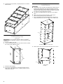
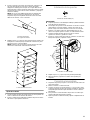
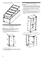
Attach Back Panels
IMPORTANT:
■ Attach the back panels starting at the top of the cabinet with
back panel (AAA) and working down to the cabinet bottom. Each
back panel will overlap the panel below.
■ Do not completely tighten the screws until all back panels are in
place.
1. Align back panel (AAA) with the holes in the cabinet top. Using
Phillips-head screws (F3c), attach back panel (AAA) to the
cabinet top and sides.
2. Slide the top of back panel (BBB) under the bottom of back panel
(AAA). Using Phillips-head screws, fasten back panel (BBB) to
the cabinet sides.
3. Repeat Step 2 for the remaining back panels ending with back
panel (EEE).
4. Using Phillips-head screws, attach each back panel to the panel
below.
NOTE: Using Phillips-head screws, attach panel (EEE) to the
cabinet bottom (P3).
5. Completely tighten all back panel screws starting with the sides
and continuing with the top, middle and bottom.
F1 F2
F1
⁵⁄₁₆
" Hex-head bolt (28)
F2
⁵⁄₁₆
" Flange nut (12)
■ ¹⁄₂" Wrench
■ Phillips screwdriver
■ Level
■ Hex key ■ Key
WARNING
Excessive Weight Hazard
Use two or more people to move, assemble or install
cabinet.
Failure to do so can result in back or other injury.
F3c
Phillips-head screw (34)
P1
P1
P2
P3
P1
P2

4
6. Using the hex key (provided), completely tighten all 28 cabinet
bolts and nuts.
Install Leveling Legs
(optional)
IMPORTANT: If you are going to install the cabinet on Gladiator
®
GearWall
®
panels or GearTrack
®
channels, you do not need to install
leveling legs.
1. Place the cabinet on its side.
2. Screw a leveling leg (P4) into each of the four rivet nuts located at
the corners of the cabinet as shown.
3. Stand the cabinet upright.
4. If you have not already done so, fasten the two bolts at each
front corner, of the cabinet frame. Completely tighten all of the
cabinet bolts and nuts.
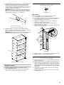
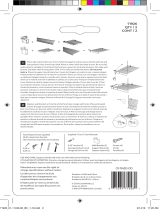
Install Shelves
IMPORTANT:
■ Use the pair of slots located in the middle of the cabinet sides to
install a center shelf (P5ml). The magnet should be on the left-
hand side and facing out when installed, so that the door closure
will make contact with the shelf, and the door will lock. The other
two shelves may be installed where desired.
■ The shelves are supported by the metal slots on the cabinet
sides.
■ Make sure that the shelf (P5ml) magnet is visible on the
left-hand side and facing out as shown below.
1. Place a shelf (P5ml) so that the two tabs in the shelf ends are
aligned with the pair of slots in the middle of the cabinet sides.
2. Tilt the shelf so that one end is higher than the other as shown.
A. Leveling legs
P1
P3
P1
P2
AAA
BBB
CCC
DDD
EEE
A
P3
P1
P4
EEE
A. Middle pair of slots in cabinet side
A. Push down.
B. Lift up.
P1
P2
P1
P3
P5ml
A
A
B

5
3. Insert the shelf into the cabinet so that the higher end is directly
above the desired slots and push the shelf down into place
behind the side slots. Raise the lower end so it is directly above
the desired slots and push the shelf down.
NOTE: You may need to slightly bend the shelf tabs outward for
the tabs to engage in the slots. Make sure the shelf tabs are in
place behind all the slots, as shown.
4. Repeat steps 2 and 3 for the remaining two shelves (P5mr). The
magnet for shelves (P5mr) is located on the right-hand side and
facing out as shown below.
NOTE: Make sure the magnet in the right of each long shelf
edge, is facing outward.
Adjust the Shelves
1. Lift up on the underside of the shelf until the shelf tabs are free of
the cabinet slots.
2. Tilt the shelf up to reposition it within the cabinet or to remove it
from the cabinet.
Install Doors
IMPORTANT:
■ The door with the lock assembly (P7) should be installed on the
right-hand side of the cabinet.
■ The door hinges are designed with keyhole slots at the top and
bottom so the door will hang on the cabinet while you are
fastening the screws.
1. Start Phillips-head screws (F3c) in both the top and bottom holes
on each side of the cabinet.
2. Hang the right-hand side door (P7) from the top and bottom
screws, and hand tighten.
3. Insert the middle four screws through the door hinge into the
cabinet and hand tighten.
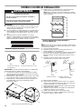
INSTALLATION INSTRUCTIONS
IMPORTANT:
■ Gladiator brand Premier Jumbo cabinet is designed to be
installed on Gladiator
®
GearWall
®
panels or GearTrack
®
channels.
■ If GearTrack
®
channels will be used to support the Gladiator
®
Premier Jumbo GearBox cabinet, you must use three channels
installed 18" (45.72 cm) apart.
■ Be sure the GearWall
®
panels or GearTrack
®
channels are
installed with mounting screws in every slot and at every stud
location with a maximum of 24" (60.96 cm) horizontally between
screws.
A. Cabinet slot
B. Shelf tab
A. Magnet facing outward
A
B
P1
P1
P2
P3
P5mr
P5ml
P5mr
A
F3c
Phillips-head screw (12)
A. Phillips-head screws
P1
P2
P5mr
P5ml
P5mr
P3
P7
A
WARNING
Excessive Weight Hazard
Use two or more people to move, assemble or install
cabinet.
Failure to do so can result in back or other injury.
18" (46 cm)

6
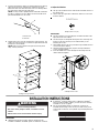
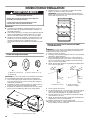
Attach Mounting Brackets
IMPORTANT: There are slots in back panels (AAA, CCC, and DDD) to
attach the mounting brackets (P8).
1. With the mounting bracket rim pointing down, align the three
bracket holes with the slots in back panel (AAA), as shown.
2. Working from the back, insert carriage bolts (F7) through the
bracket and into top back panel (AAA).
3. Working from the cabinet interior, fasten each bolt with a
washer (F8) and a flange nut (F2). Fully tighten the bolts.
4. Repeat steps 1 and 2 to attach the center and bottom mounting
brackets (P8) to the back of the cabinet.
NOTE: Hand tighten the nuts attaching the center and bottom
brackets. These brackets will need to be adjusted to mount the
cabinet on the wall.
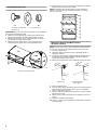
Mount the Cabinet to GearWall
®
Panels or
GearTrack
®
Channel
NOTE: The three nuts on the center and bottom mounting brackets
must be loose enough to allow the brackets to move in the slots.
1. Close the cabinet doors.
2. Determine cabinet mounting location on GearWall
®
panels or
GearTrack
®
channel.
3. Using two or more people, engage the top bracket (P8) into the
slots by lifting up, pushing toward the wall and lowering the
bracket rims into the slots as shown.
4. Make sure the top bracket is fully engaged in the slots as shown.
5. Open the cabinet doors.
6. From inside the cabinet, grasp the bolts in the center bracket and
adjust the bracket until it aligns with the slot in the GearWall
®
panels or GearTrack
®
channels.
7. Push the cabinet toward the wall and lower the center mounting
bracket into the slots.
8. Make sure the center bracket (P8) is fully engaged in the slot as
shown.
9. Repeat for the bottom bracket (P8).
10. Using a ¹⁄₂" wrench, fully tighten the nuts attaching the center and
bottom brackets.
F7 F8 F2
F7 Carriage-head bolt (9)
F8 Washer (9)
F2
⁵⁄₁₆
" Flange nut (9)
A. Bracket rims pointing down
AAA
BBB
P1
P8
P8
A
P2
P1
AAA
A. Bracket rim B. Mounting bracket
fully engaged
A
B

7
GLADIATOR
®
GARAGEWORKS
PREMIER JUMBO CABINET WARRANTY
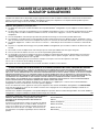
LIFETIME LIMITED WARRANTY
For the life of the product, when the Premier Jumbo Cabinet is used and maintained according to the instructions attached to or
furnished with the product, Gladiator
®
GarageWorks will pay for replacement or repair of the defective product or parts to correct
defects in materials or workmanship.
Gladiator
®
GarageWorks will not pay for:
1. Service calls to correct the installation of any Gladiator
®
GarageWorks products or to instruct you on how to use or install them.
2. Damage resulting from improper handling or shipping of products, or products damaged by accident, misuse, abuse, fire, flood,
improper installation, acts of God, neglect, corrosion, modification or mishandling.
3. Shipping or freight fees to deliver replacement products or to return defective products.
4. Repairs or replacement when your product is used in other than normal, single-family household use, such as a commercial
environment or handled in any way inconsistent with the installation instructions included with the product.
5. Cosmetic damage including scratches, dings, dents or cracks that do not affect the structural or functional capability of the
product.
6. Replacement parts or product for Gladiator
®
GarageWorks products operated outside the United States and Canada.
7. In Canada, travel or transportation expenses for customers who reside in remote areas.
8. Any labor costs during the limited warranty period.
9. Damage resulting from improper loading beyond the specified maximum weight capacity outlined in the assembly instructions
provided with the product, including overloading of hooks, baskets, shelves, cabinets, and other Gladiator
®
GarageWorks
accessories used with the product.
10. Surfaces damaged due to chemical interaction resulting in corrosion of paint or metal.
11. Replacement keys or locking mechanism.
12. Loss of product contents due to theft, fire, flood, accident or acts of God.
DISCLAIMER OF IMPLIED WARRANTIES; LIMITATION OF REMEDIES
IMPLIED WARRANTIES, INCLUDING TO THE EXTENT APPLICABLE WARRANTIES OF MERCHANTABILITY OR FITNESS FOR A
PARTICULAR PURPOSE, ARE EXCLUDED TO THE EXTENT LEGALLY PERMISSIBLE. ANY IMPLIED WARRANTIES THAT MAY BE
IMPOSED BY LAW ARE LIMITED TO ONE YEAR, OR THE SHORTEST PERIOD ALLOWED BY LAW. SOME STATES AND PROVINCES
DO NOT ALLOW LIMITATIONS OR EXCLUSIONS ON HOW LONG AN IMPLIED WARRANTY OF MERCHANTABILITY OR FITNESS
LASTS, SO THE ABOVE LIMITATIONS OR EXCLUSIONS MAY NOT APPLY TO YOU. THIS WARRANTY GIVES YOU SPECIFIC LEGAL
RIGHTS, AND YOU MAY ALSO HAVE OTHER RIGHTS WHICH VARY FROM STATE TO STATE OR PROVINCE TO PROVINCE.
Outside the 50 United States and Canada, this warranty does not apply. Contact your authorized Gladiator
®
GarageWorks dealer to
determine if another warranty applies.
If you need service, call the Gladiator
®
GarageWorks Customer eXperience Center, 1-866-342-4089 (toll-free), from anywhere in the
U.S.A. In Canada, contact your Whirlpool Canada LP designated service company or call 1-800-807-6777.
In the United States, Gladiator
®
GarageWorks means Whirlpool Corporation, Benton Harbor, Michigan 49022. In Canada, Gladiator
®
GarageWorks means Whirlpool Canada LP, Mississauga, ON L5N 3A7. 3/07
Keep this book and your sales slip together for future
reference. You must provide proof of purchase or installation
date for in-warranty service.
Write down the following information about your Premier Jumbo
Cabinet to better help you obtain assistance or service if you ever
need it. You will need to know your complete model number and
serial number. You can find this information on the model and
serial label located on the back of the product.
Dealer name____________________________________________________
Address________________________________________________________
Phone number__________________________________________________
Model number __________________________________________________
Serial number __________________________________________________
Purchase date __________________________________________________
Page is loading ...
Page is loading ...
Page is loading ...
Page is loading ...
Page is loading ...
Page is loading ...
Page is loading ...
Page is loading ...
Page is loading ...
Page is loading ...
Page is loading ...
Page is loading ...

W10130911C
© 2011 Whirlpool Corporation.
All rights reserved.
Todos los derechos reservados.
Tous droits réservés.
® Registered Trademark/TM Trademark of Whirlpool, U.S.A., Whirlpool Canada LP Licensee in Canada
® Marca registrada/TM Marca de comercio de Whirlpool, U.S.A., usada bajo licencia de Whirlpool Canada LP en Canadá
® Marque déposée/TM Marque de commerce de Whirlpool, U.S.A., emploi sous licence par Whirlpool Canada LP au Canada
9/11
Printed in China
Impreso en China
Imprimé en Chine
-
 1
1
-
 2
2
-
 3
3
-
 4
4
-
 5
5
-
 6
6
-
 7
7
-
 8
8
-
 9
9
-
 10
10
-
 11
11
-
 12
12
-
 13
13
-
 14
14
-
 15
15
-
 16
16
-
 17
17
-
 18
18
-
 19
19
-
 20
20


Gladiator GAJG36FDYG Installation guide
- Category
- AV equipment stands
- Type
- Installation guide
- This manual is also suitable for
Ask a question and I''ll find the answer in the document
Finding information in a document is now easier with AI
in other languages
Related papers
-
Gladiator GAJG48KDYG User manual
-
-
-
-
Gladiator GAAC68PSDG User manual
-
-
Gladiator GAWA48SFZW User manual
-
-
-
Other documents
-
 Officemate 91990 User manual
-
Ryobi STM405 Owner's manual
-
Liberty C081P0C-T-P1 Installation guide
-
 Gladiator Garageworks 2253351A User manual
-
 Gladiator Garageworks 2253694A User manual
-
Whirlpool GARF06XXMG00 User manual
-
 ClosetMaid Wall bracket Installation guide
-
Jacuzzi PD50000 User guide
-
 DV8 OFFROAD RRGL-01 Installation guide
-
Rubbermaid FG788800MICHR Operating instructions


