Page is loading ...

05-95333-95334-0CPage 1
14' x 28' x 12' Round Top
®
Round Style Shelter
Assembly Instructions
DESCRIPTION MODEL #
14' x 28' x 12' RoundTop Garage
®
- Gray
95333
14' x 28' x 12' RoundTop Garage
®
- Green
95334
Before you start: 2+ individual recommended for assembly, approximate time 3 hr.
Please read instructions COMPLETELY before assembly. This shelter MUST be securely anchored.
THIS IS A TEMPORARY STRUCTURE AND NOT RECOMMENDED AS A PERMANENT STRUCTURE.
1-800-524-9970
1-800-559-6175
Canada:
RECOMMENDED TOOLS
150 Callender Road
Watertown, CT 06795
www.shelterlogic.com
6/21/10

05-95333-95334-0CPage 2
Risk of re. DO NOT smoke or use open ame devices (including grills, re pits, deep fryers, smokers or
lanterns) in or around the shelter. DO NOT store ammable liquids (gasoline, kerosene, propane, etc.) in
or around your shelter. Do not expose top or sides of the shelter to open re or other ame source.
WARNING:
CAUTION:
PROPER ANCHORING OF THE FRAME IS THE RESPONSIBILITY OF THE CONSUMER.
ShelterLogic
®
, LLC
is not responsible for damage to the unit or the contents from acts of nature. Any shelter that is not anchored
securely has the potential to y away causing damage, and is not covered under the warranty. Periodically check the anchors to ensure
stability of shelter. ShelterLogic
®
, LLC cannot be responsible for any shelter that blows away. NOTE: Your shelter’s cover can be
quickly removed and stored prior to severe weather conditions. If strong winds or severe weather is forecast in your area, we
recommend removal of cover.
PROPER ANCHORING AND INSTALLATION OF FRAME:
A tight cover ensures longer life and performance. Always maintain a tight cover. Loose fabric can accelerate
deterioration of cover fabric. Immediately remove any accumulated snow or ice from the roof structure with a
broom, mop or other soft-sided instrument. Use extreme caution when removing snow from cover- always
remove from outside the structure. DO NOT use hard-edged tools or instruments like rakes or shovels to
remove snow. This could result in punctures to the cover. DO NOT use bleach or harsh abrasive products to
clean the fabric cover. Cover is easily cleaned with mild soap and water.
Covered by U.S. Patents and patents pending: 6,871,614; 6,994,099; 7,296,584; D 430,306; D 415,571; D 414,564; D 409,310; D 415,572
CARE AND CLEANING:
Prior to installation, consult with all local municipal codes regarding installation of temporary shelters.
Choose the location of your shelter carefully. DANGER: Keep away from electrical wires. Check for
overhead utility lines, tree branches or other structures. Check for underground pipes or wires before
you dig. DO NOT install near roof lines or other structures that could shed snow, ice or excessive run
off onto your shelter. DO NOT hang objects from the roof or support cables.
ATTENTION:
This shelter product is manufactured with quality materials. It is designed to t the ShelterLogic
®
, LLC custom fabric cover included.
ShelterLogic
®
, LLC Shelters offer storage and protection from damage caused by sun, light rain, tree sap, animal - bird excrement
and light snow. Please anchor this ShelterLogic
®
, LLC structure properly. See manual for more anchoring details. Proper anchoring,
keeping cover tight and free of snow and debris is the responsibility of the consumer. Please read and understand the installation detail,
warnings and cautions prior to beginning installation. If you have any questions call the customer service number listed below. Please
refer to the warranty card inside this package.
DANGER:
Use CAUTION when erecting the frame. Use safety goggles during installation. Secure and bolt together
overhead poles during assembly. Beware of pole ends.
REPLACEMENT PARTS, ASSEMBLY, SPECIAL ORDERS:
Genuine ShelterLogic
®
, LLC replacement parts and accessories are available from the factory, including anchoring kits for nearly any
application, replacement covers, wall and enclosure kits, vent and light kits, frame parts, zippered doors and other accessories. All
items are shipped factory direct to your door.
This shelter carries a full limited warranty against defects in workmanship. ShelterLogic
®
, LLC warrants to the Original Purchaser that if
properly used and installed, the product and all associated parts, are free from manufacturer’s defects for a period of:
1 YEAR FOR COvER FABRIC, END PANELS AND FRAMEWORk
Warranty period is determined by date of shipment from ShelterLogic
®
, LLC for factory direct purchases or date of purchase from an authorized
reseller, (please save a copy of your purchase receipt). If this product or any associated parts are found to be defective or missing at the time of receipt,
ShelterLogic
®
, LLC will repair or replace, at it’s option, the defective parts at no charge to the original purchaser. Replacement parts or repaired parts
shall be covered for the remainder of the Original Limited Warranty Period. All shipping costs will be the responsibility of the customer. Parts and replace-
ments will be sent C.O.D. You must save the original packaging materials for shipment back. If you purchased from a local dealer, all claims must have a
copy of original receipt. After purchase, please ll out and return warranty card for product registration. Please see warranty card for more details.
WARRANTY:
QUESTIONS - CLAIMS - SPECIAL ORDERS? CALL OUR CUSTOMER SERVICE HOTLINE:
U.S. CUSTOMER SERVICE: 1-800-524-9970 INTERNATIONAL CUSTOMER SERVICE: 001-860-945-6442 CANADA CUSTOMER SERVICE: 1-800-559-6175
HOURS OF OPERATION: MON-FRI 8:30AM-8:00PM EST, SAT-SUN 8:30AM-5:00PM EST.

05-95333-95334-0CPage 3
14' x 28' x 12' RoundTop
®
Garage Parts List - Model # 95333 or 95334
Quantity Part #
Top Bend Tube
Side Bend Tube
4 11179
4-Way Half-Clamps for Middle Legs
4
11182
Cover - Grey (if model # 95333)
Cover - Green (if model # 95334)
1
1
2A2353
2A2354
2 - Zipper Door - Grey (if model # 95333)
2 - Zipper Door - Green (if model # 95334)
Ratchet Clamp
8 10040
24 11107
Description of Parts:
Cross Rail, plain end 48.5 in. / 123,2 cm
Cover Rail, plain end 45 in. / 114,3 cm
16 11051
Cross Rail, Swedged 50 in. / 127 cm
18
11102
Middle Upright Tube 40 in. / 101,6 cm
3
11104
2
2
2E2053
2E2054
Wind Brace (Flat Ends)
Wind Brace (Swedged Ends)
14
11105
Bent Corner Leg
4 11005
Bolts 2 1/4 x
5
/
16
in. / 57,2 x 8 mm
28
11130
Bolts 2 3/4 x
5
/
16
in. / 69,9 x 8 mm
Bolts 4
1
/
8
x
5
/
16
in. / 104,8 x 8 mm
68
18
11131
800454
3-Way Half-Clamps for Corner Legs
8
11106
800372
Bolts 2 x
5
/
16
in. / 51 x 8 mm
4
00648
Nut
5
/
16
in. / 8 mm
124 00690
Extension 48.9 in / 124,2 cm
8
16
16
11114
11113
Round Head Bolts 4 x
5
/
16
in. / 101,6 x 8 mm
6
11133
Bolt Caps
Base Feet
20 11150
12
800057
12
11112
30" Auger Anchors (Temporary)
Cable Clamps
Cable - 1' Length
00822
10015
10016
10
10
10
ShelterLock
™

05-95333-95334-0CPage 4
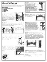
2. ASSEMBLE END RIBS
Assemble end ribs as shown in Fig. 2. Securely
fasten all of the joints with the hardware indicated.
3. ASSEMBLE MIDDLE RIBS
Assemble middle ribs as shown in Fig. 3. Securely
fasten all of the joints with the hardware indicated.
#11131
5/16"x2 3/4"
Bolts
11051
11051
11182
11113
11113
11114
11182
#11131
5/16"x2 3/4"
Bolts
11051
11051
11112
11112
11113
11113
11114
Fig.2
Fig.3
1. PLOTTING THE AREA FOR THE FRAME:
A. Stake out the area for the frame in the desired spot. Ensure that the
shelter measures the purchased length and width. Measure diagonally
from corner to opposite corner (A), and repeat this measurement with
the remaining two corners (B).
B. To ensure the building is squared, both A and B measurements
should be the same. Check the rectangle's length and width once
more, as they may have changed during the squaring-up procedure.
Once length and width are veried, and measurements A and B are
equal, your shelter should be square.
A
B
28 ft.
LENGTH
14 ft.
WIDTH
Fig.1

05-95333-95334-0CPage 5
4. ATTACH BASE FEET TO MIDDLE RIBS
Insert a base foot plate into each end of the middle rib pipes.
After installing the base feet line up the holes in the leg to the holes in
the feet and secure with the hardware indicated in Fig. 4.
Fig.4
00690
11112
800057
11131
5. ASSEMBLE WIND BRACES
Assemble all of the wind braces as shown in Fig. 5.
Securely fasten all of the joints with the hardware
indicated.
Use #00648 5/16" x 2" Bolts
11005 11179
Fig.5
Fig.6
6. INSTALL SIDE RAILS AND SHELTERLOCK
™
STABILIZER BLOCKS
With help, move the rst end rib into the desired staked area.
Place the ShelterLock
™
on the upright as shown in Fig. 6.
From the outside of the rib insert the bolt through the upright and then
through the ShelterLock
™
.
Place the plain end of the side rail over the bolt and nest it into the
ShelterLock
™
.
Install the nut onto the bolt and tighten.
Repeat these steps for the opposite side and all of the remaining ribs.
The side rails for the last rib will have two plain ends.
11102
11102
800454
800372
00690

05-95333-95334-0CPage 6
7. INSTALL WIND BRACES
Take the wind brace and attach it between the end rib and
the rst middle rib as shown in Fig. 7.
Any attachments at the cross rails should be made on the
very inside of the cross rail.
8. INSTALL TOP RAIL
Place the rst top rail under the end rib and secure it with a bolt as shown in Fig. 8.
The same cross rail should lay on top of the rst middle rib as with all of the middle ribs.
Secure the rails to the frame with the hardware indicated in Fig 8.
The top rail attached to the last rib will be installed under the pipe as the initial end rib.
Wind
Brace
Wind
Brace
11102
11102
11
102
11102
11005-11179
11005-11179
Fig.8
Top Cross Rail UNDER End Ribs
800454
11133
00690
00690
Top Cross Rail OVER Middle Ribs
Fig. 9
9. INSTALL AUGER ANCHORS
Using a ¾” pipe or steel rod (a car tire iron works also) placed
through the eyelet of the auger; screw the anchor into the ground.
Start at the corners of the shelter and space the remaining anchors
evenly along the length of the shelter.
Screw the anchor into the ground until the eyelet is sticking out of
the ground by 1-2” so it can be anchored to the legs.
Wrap the cable provided through the eyelet of the anchor and
around the frame as indicated in Fig. 9. Secure the cable with the
clamps provided.
Fig.7

05-95333-95334-0CPage 7
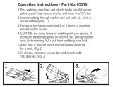
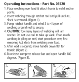
10. DOOR AND SOLID END PANEL INSTALLATION
A. Hold end panel at the top center with white inner surface facing inside of the shelter. Wrap the edges of the
fabric panel around the end rib and pass the rails through the pre made slits in the fabric.
B. Disconnect top rail from the end rib. The top cross rail should pass through the slit in the fabric, and be
inbetween the webbing and rib frame. Cut slit as needed to get cover tight.
Repeat Step B for side cross rails and wind braces.
C. At the bottom, where the webbing exits the pocket on each side of end panel, pull webbing to remove the
slack. Be careful not to pull the webbing through the other side of the webbing pocket.
D. Insert the “S”- Hook on ratchet into hole on the leg bend. Insert the webbing into the spindle of the ratchet
and pull tight. Wind the ratchet so that the webbing overlaps itself.
Position the end panel so that it is centered on the building before fully tightening the end panel.
E. Tighten ratchets, alternating from one side to the other, until the end panel is tight.
Zipper Door Panels: Zippers must be closed when tightening end panel.
Thread Webbing Into Ratchet
SIDE CROSS
RAILS
WEBBING
ZIPPERS
TOP CROSS
RAIL
WRAP END
PANEL EDGES
TO INSIDE OF
FRAME
WRAP END PANEL EDGES TO INSIDE OF FRAME
INSIDE VIEW OF END RIB SIDE VIEW OF END RIB
WIND
BRACE
Webbing and Ratchets Securing End Panel

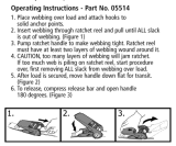
05-95333-95334-0CPage 8
A. Lay the cover on the ground next to the
frame with the inside of the cover (the side
with the pipe pockets) facing down and the
webbing on the front and rear of the corner
of the building. Position the cover so that it is
centered on the frame, front to back. Fig. 11A
B. Fold over the side closest to the frame so
the pipe pocket is now accessible. Insert a
cover pipe at the rst middle rib from the front
and the rst middle rib from the rear so that it
is inserted in the pipe pocket on both ends of
the pipe but the center of the pipe is exposed.
For long buildings it may be necessary to use
additional pipes in the middle. Fig. 11B.
C. Tie the rope on each of the exposed pipes
and throw the other end of the rope over the
frame. Fig. 11C.
D. Move to the other side of the frame and
pull the cover over the frame with the rope.
This may require two or more people.
Fig. 11D
Fig. 11A
Fig. 11B
Fig. 11C
Fig. 11D
11. INSTALLING THE COVER ON THE FRAME

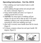
05-95333-95334-0CPage 9
Fig. 12A
Fig. 12B
Webbing and Ratchets Securing Cover
Thread Webbing Into Ratchet
A. Install the “S”-hook from the ratchet assembly into the legs of
the shelter. Pull the webbing carefully to remove the slack from the
cover. Be careful not to pull the webbing through the opposite side
of the cover. Insert the webbing through the spindle of the ratchet
and pull tight. Wind the ratchet until the webbing overlaps itself.
Repeat these steps on the opposite side. Repeat this on the back
side of the shelter. When all of the corners are secured move the
cover front to back so that it is centered.When the cover is cen-
tered tighten all of the ratchets. Do this in an “X” pattern to be sure
it is tightened evenly. Fig. 12A & 12B.
B. When the cover is tight from end to end install the 45” cover
rails. Insert the cover rails into the pockets of the cover. Clamp
the rails to the ribs using the 3-way and 4-way clamps as shown in
Fig. 13 & 14.
C. Check that the rails are evenly spaced above the ground on
both sides. Push down on the connectors, one at a time, to tighten
the cover. Tighten the bolts to the cover in place and tight on the
frame.
12. SECURE YOUR COVER
11105
COVER RAILS
NOTE: The ShelterLogic
®
logo should
be oriented as shown below.
FRONT
REAR
End Rib Cross Rail Clamps
11130
11105
11106
11182
00690
Fig. 13
Middle Rib Cross Rail Clamps
11130
11105
11105
11107
11112
00690
00690
Fig. 14
/