Broan 656 Operating instructions
- Category
- Space heaters
- Type
- Operating instructions
This manual is also suitable for

1
INSTRUCCIONES IMPORTANTES
LEA TODAS LAS INSTRUCCIONES ANTES DE INSTALAR
O USAR ESTE CALENTADOR.
Para reducir el riesgo de incendios, descargas eléctricas o lesiones personales,
observe las siguientes precauciones:
1. Use la unidad solo de la manera indicada por el fabricante. Si tiene preguntas,
comuníquese con el fabricante a la dirección o al número telefónico que se
incluye en la garantía.
2. Antes de dar servicio a la unidad o de limpiarla, interrumpa el suministro eléctrico
en el panel de servicio y bloquee los medios de desconexión del servicio para
evitar que la electricidad se reanude accidentalmente. Cuando no sea posible
bloquear los medios de desconexión del servicio, fije firmemente una señal de
advertencia (como una etiqueta) en un lugar visible del panel de servicio.
3. El trabajo de instalación y el cableado eléctrico deben estar a cargo de personal
capacitado, de acuerdo con todos los códigos y normas correspondientes,
incluidos los códigos y normas de construcción específicos sobre protección
contra incendios.
4. Al cortar o perforar a través de la pared o del cielo raso, tenga cuidado de no
dañar el cableado eléctrico ni otros servicios ocultos.
5. Este calentador se calienta cuando se usa. Para evitar quemaduras, no deje que la
piel desnuda toque las superficies calientes. Mantenga materiales combustibles
como muebles, almohadas, ropa de cama, papeles, ropa, etc., así como las
cortinas, por lo menos a 3 pies (0.9 m) de la parte delantera del calentador.
6. Es necesario tener extremo cuidado cuando se use un calentador cerca de niños
o personas inválidas, y siempre que el calentador se deje funcionando y sin
atención.
7. No haga funcionar ningún calentador después de que presente una falla.
Desconecte la energía eléctrica en el panel de servicio y pida que un electricista
acreditado inspeccione el calentador antes de volverlo a usar.
8. No lo use en exteriores.
9. Para desconectar el calentador, mueva los controles a la posición de apagado
y desconecte la energía eléctrica al circuito del calentador en el panel de
desconexión principal (o active el interruptor de desconexión interna, si existe).
10. No inserte ni permita que objetos extraños entren en la abertura de ventilación
o de escape, pues esto puede ocasionar una descarga eléctrica, un incendio o
daños al calentador.
11. Para prevenir un posible incendio, no bloquee la entrada o salida del aire de
ninguna manera.
12. El calentador tiene piezas calientes y que pueden generar arcos eléctricos o
chispas en el interior. No lo use en áreas donde se use o almacene gasolina,
pintura o vapores o líquidos flamables.
13. Use este calentador solamente como se describe en este manual. Cualquier
otro uso no recomendado por el fabricante puede ocasionar un incendio, una
descarga eléctrica o lesiones a personas.
14. Para evitar golpe eléctrico: No instale la unidad en una bañera o recinto de ducha.
Nunca coloque un interruptor en un lugar que pueda ser alcanzado desde una
bañera o ducha.
15. No conecte el calentador a un variador de luz o control de velocidad.
16. Provea un circuito por separado de 15 AMP. Use un cable de corriente 14 GA.
del tipo conforme al código.
17. Este producto está diseñado solamente para instalarse en el cielo raso. Este
producto está diseñado para instalarse en cielos rasos con una pendiente de
hasta 12/12. El sistema de conductos debe apuntar hacia arriba. NO MONTE
ESTE PRODUCTO EN LA PARED.
18. Instalar en el techo solamente por lo menos a 6" de la pared.
19. Este producto debe ser conectado a tierra.
GUARDE ESTAS INSTRUCCIONES
HERRAMIENTAS Y
MATERIALES NECESARIOS
• Destornilladores con rectos lados y Phillips
• Sierra de puntar o saber
• Martillo
• Alicates o aprieta-tuercas
SOLAMENTE PARA EL MODELO 658
• Conducto redondo de 10,16 cm ( 4 plg.) y codos (los que se necesiten)
• Techo o casquete de pared
• Cinta adhesiva para conductos
• Artículos eléctricos (que cumpla con los códigos)
COMBINATION UNITS
MODEL 656 HEATER/LIGHT
MODEL 658 HEATER/FAN
656F AND 658F FINISH PACKS FOR USE
WITH 654H HOUSING PACKS.
READ AND SAVE
THESE INSTRUCTIONS
UNIDADES COMBINADAS
MODELO 656 CALENTADOR/LUZ
MODELO 658 CALENTADOR/VENTILADOR
PAQUETES DE ACABADO 656F y 659F PARA USAR
CON PAQUETES DE BASTIDOR 654H.
IMPORTANT INSTRUCTIONS
READ ALL INSTRUCTIONS BEFORE
INSTALLING OR USING THIS HEATER.
To reduce the risk of fire, electric shock, or injury to persons,
observe the following:
1. Use this unit only in the manner intended by the manufacturer.
If you have questions, contact the manufacturer at the address
or telephone number listed in the warranty.
2. Before servicing or cleaning unit, switch power off at service
panel and lock the service disconnecting means to prevent
power from being switched on accidentally. When the service
disconnecting means cannot be locked, securely fasten a
prominent warning device, such as a tag, to the service panel.
3. Installation work and electrical wiring must be done by a
qualified person(s) in accordance with all applicable codes
and standards, including fire-rated construction codes and
standards.
4. When cutting or drilling into wall or ceiling, do not damage
electrical wiring and other hidden utilities.
5. This heater is hot when in use. To avoid burns, do not let bare
skin touch hot surfaces. Keep combustible materials, such as
furniture, pillows, bedding, papers, clothes, etc. and curtains
at least 3 feet (0.9 m) from the front of the heater.
6. Extreme caution is necessary when any heater is used by
or near children or invalids and whenever the heater is left
operating and unattended.
7. Do not operate any heater after it malfunctions. Disconnect
power at service panel and have heater inspected by a
reputable electrician before reusing.
8. Do not use outdoors.
9. To disconnect heater, turn controls to off, and turn off power
to heater circuit at main disconnect panel (or operate internal
disconnect switch, if provided).
10. Do not insert or allow foreign objects to enter any ventilation
or exhaust opening, as this may cause an electric shock or
fire, or damage the heater.
11. To prevent a possible fire, do not block air intakes or exhaust
in any manner.
12. A heater has hot and arcing or sparking parts inside. Do not
use it in areas where gasoline, paint, or flammable vapors or
liquids are used or stored.
13. Use this heater only as described in this manual. Any other
use not recommended by the manufacturer may cause fire,
electric shock, or injury to persons.
14. To avoid electrical shock: Do not install unit in a tub or shower
enclosure or any location where it may come in contact with
water. Never place a switch where it can be reached from a tub
or shower.
15. Do not connect heater to dimmer switch or speed control.
16. Provide a separate 15 AMP circuit. Use 14 GA. power cable of
type which meets code.
17. This product is designed for ceiling installation only. This prod-
uct is designed for installation in ceilings up to a12/12 pitch.
Ductwork must point up. DO NOT MOUNT THIS PRODUCT IN
A WALL.
18. Install in ceiling only, at least 6" from any wall.
19. The product must be grounded.
SAVE THESE INSTRUCTIONS
TOOLS AND
MATERIALS REQUIRED
• Straight-blade & Phillips screwdrivers
• Saber or Keyhole Saw
• Hammer
• Pliers or Nut Driver
MODEL 658 ONLY
• 4” round duct and elbows (as needed)
• Roof or wall cap
• Duct tape
• Electrical supplies (to comply with codes)
LEA Y CONSERVE
ESTAS INSTRUCCIONES

2
PREPARACION
1. Desconecte el conjunto del calentador del enchufe ROJO.
2. Afloje los dos tornillos de retén en el interior de la entrada
de descarga del calentador.
Coloque la punta del destornillador entre la pared exterior
de la entrada de descarga y la carcasa del ventilador.
Haga palanca suavemente hacia afuera hasta que la
descarga del escape salga de la pestaña de apoyo en
la carcasa exterior. (FIG. 1)
3. Desenganche los pasadores de la bisagra y saque el
conjunto del calentador hacia afuera de la carcasa. (FIG. 2)
PASOS 4 Y 5 - SOLAMENTE PARA EL MODELO 658
4. Desconecte el ventilador del enchufe NEGRO. Saque
la bolsa de plástico y déjela a un lado.
5. Quite el tornillo de montaje y cuidadosamente saque
el ventilador hacia afuera de la carcasa. (FIG. 3)
6. Refiérase al diagrama de conexiones de la unidad
en la página siguiente. Saque los discos removibles
apropiados introduciendo la punta del desmontador en las
ranuras y moviendo éste de un lado a otro hasta romper
las pestañas. (FIG. 4)
7. Inserte lo soportes de montaje ajustables en los canales
para los soportes en la carcasa. (FIG. 5)
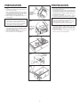
PREPARATION
1. Unplug the heater assembly from the RED recep-
tacle.
2. Loosen the two retaining screws on the inside of the
heater discharge opening.
Place a screwdriver tip between the outer wall of
the discharge opening and the fan housing. Gently
pry outward until the exhaust discharge slips off the
support lip on the outer housing. (FIG. 1)
3. Unhook hinge pins and lift heater assembly out of
housing. (FIG. 2)
STEPS 4 & 5 - MODEL 658 ONLY
4. Unplug the fan assembly from the BLACK recep-
tacle. Remove the plastic bag and set it aside.
5. Remove the mounting screw and carefully lift the
fan assembly out of the housing. (FIG. 3)
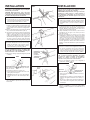
6. Refer to the wiring diagram of your unit on the next
page. Remove appropriate knockout(s) by inserting
a screwdriver blade into slots and bending it back
and forth to break tabs. (FIG. 4)
7. Insert the adjustable mounting brackets into the
bracket channels on the housing. (FIG. 5)
FIG. 1
RETAINING
SCREWS
TORNILLOS DE
RETEN
FIG. 2
HINGE PINS
PASADORES
DE LA BIS-
AGRA
FIG. 3
FIG. 4
FIG. 5
KNOCKOUTS
DISCOS
REMOVIBLES

WIRING OPENING
RELEASE SLOT
INSTALLATION
WARNING: To reduce the risk of fire, do not store or
use gasoline or other flammable vapors and liquids
in the vicinity of the heater.
CAUTION: High temperature, risk of fire, keep
electrical cords, drapery, furnishings, and other
combustibles at least 3 feet (0.9 m) from the front of
the heater and away from the side and rear.
STEP 8 - MODEL 658 ONLY
8. For best results, choose a location which allows
fan to be vented outside with the shortest possible
duct run and the fewest number of elbows.
9. Position unit between joists and extend mounting
brackets. Position brackets such that bottom edge
of housing will be flush with finished ceiling. Mark
the top of keyhole slot on all four mounting brackets.
(FIG. 6)
10. Remove unit temporarily, and pound nails partially
into joists at all four marked locations. (FIG. 7)
11. Hang unit from nails and use embossed measuring
guides to check if unit will be flush with finished
ceiling. Pound nails tight. For wide joist centers:
A #8 x 3/8 self-tapping screw can be used to join
extended brackets together and create a rigid mount.
To ensure a noise-free mount, crimp the bracket
channels tightly around mounting brackets. (FIG. 8)
STEP 12 - MODEL 658 ONLY
12. Snap the damper/duct connector onto housing.
Make sure that tabs on the connector lock in
housing slots. (Top of damper/duct connector
will be flush with top of housing.) (FIG. 9)
Installation work and electrical wiring must be
done by a qualified person(s) in accordance with
all applicable codes and standards, including fire-
rated construction codes and standards.
13. Wire unit according to appropriate diagram. (FIG.10
or FIG.11)
NOTE
If the switch has not been wired properly and wires
need to be moved:
1. Each wire opening has a release slot.
2. Push a small nail or screwdriver into release slot
while gently removing wire.
3. DO NOT pull any wire out of the switch without
using the release slot. The switch may be dam-
aged.
14. Replace heater assembly removed in STEP 3 and
plug it into RED receptacle. Direct wires away from
blower inlet.
INSTALACION
ADVERTENCIA: Para reducir el riesgo de incendio, no
almacene ni use gasolina u otros vapores y líquidos
flamables en las cercanías del calentador.
PRECAUCIÓN: Temperatura alta, el riesgo de incendio,
mantenga los cables eléctricos, cortinas, muebles y
otros materiales combustibles por lo menos 3 pies
(0,9 m) del frente del calentador y lejos de la cara y la
parte trasera.
PASO 8 - SOLAMENTE PARA EL MODELO 658
8. Para mejores resultados, elija un lugar que permita
que el ventilador ventile hacia afuera usando la menor
cantidad de ducto y el menor número posible de
codos.
9. Sitúe la unidad entre las vigas y extienda lo soportes
de montaje. Coloque los soportes de manera que el
extremo inferior de la carcasa quede al nivel del techo
acabado. Marque la parte superior de la ranura en los
cuatro soportes de montaje. (FIG. 6)
10. Saque la unidad por unos momentos, y clave los clavos
parcialmente en las vigas en las cuatro posiciones
marcadas. (FIG. 7)
11. Cuelgue la unidad de los clavos y use las guías
estampadas de medición para comprobar si la unidad
se encuentra a nivel con el techo acabado. Termine de
clavar los clavos. En caso de que el centro de las vigas
sea ancho: se puede usar un tornillo autoencroscables
No. 8 x 3/8 para juntar lo soportes extendidos y crear una
montura rígida. Para obtener una montura silenciosa,
pliegue los canales alrededor de los soportes de montaje.
(FIG. 8)
PASO 12 - SOLAMENTE PARA EL MODELO 658
12. Inserte la conexión del amortiguadorr/conducto en
la carcasa. Compruebe de que las pestañas del
conector enganchan en las ranuras de la caja.(La
parte superior del amortiguadorr/conducto debe estar
a nivel con la parte superior de la carcasa). (FIG. 9)
El trabajo de instalación y el cableado eléctrico deben
estar a cargo de personal capacitado, de acuerdo
con todos los códigos y normas correspondientes,
incluidos los códigos y normas de construcción
específicos sobre protección contra incendios.
13. Conecte la unidad de acuerdo con el diagrama a
continuación. (FIG.10 o FIG. 11)
NOTA
14. Vuelva a colocar el conjunto del calentador que fue
retirado en el PASO 3 y conéctelo al enchufe ROJO.
Instale los alambres alejados de la entrada de aire al
ventilador.
RANURA DE DE-
SENGANCHE
ENTRADA
PARA EL CABLE
1. Cada entrada para cable posee una ranura de
desenganche.
2. Introduzca un clavo pequeño o un destornillador en la
ranura de desenganche mientras saca el cable poco
a poco.
3. No tire de los cables hacia afuera del interruptor sin
usar la ranura de desenganche. Esto puede dañar
el interruptor.
FIG. 6
FIG. 7
FIG. 8
FIG. 9
EMBOSSED
MEASURING
GUIDES
GUIAS ES-
TAMPADAS DE
MEDICION
FLUSH
NIVEL

4
PASO 15 - SOLAMENTE PARA
EL MODELO 658
15. Vuelva a colocar el conjunto del
ventilador que fue retirado en el paso
5 y conéctelo al enchufe NEGRO.
PASOS 16 y 17 - SOLAMENTE PARA EL
MODELO 656
PRECAUCION:
Para evitar la posibilidad de un so-
brecalentamiento y/o un incendio, la
rejilla debe ser instalada se muestra
en Fig. 12. La tuerca ciega debe co-
nectarse a la varilla roscada a través
del agujero apropiado en el reflector
de luz.
16. Deslice el reflector de luz en la
abertura de la rejilla y conéctelo al
enchufe BLANCO. Use la tuerca en la
bolsa de plástico para sujetar la rejilla
y el reflector de luz a la varilla roscada
de la carcasa. Apriete con fuerza
usando el alicate o el aprietatuercas.
instale una bombilla de un máximo de
100 watios. (FIG. 12)
17. Para instalar el lente de la luz: 1)
Enganche una de las pestañas en
la muesca del conjunto de rejilla/
reflector; 2) Aplique un poco de
presión a la otra pestaña con las
yemas de los dedos, y 3) Encájela en
su sitio. (FIG. 13)
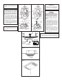
HEAT
CALOR
LIGHT
LUZ
RED
ROJO
BLK
NEGRO
BLK
NEGRO
120 VAC LINE IN
LINEA DE ENTRADA
A 120 VCA
WHT
BLANCO
GRD
TIERRA
WHT
BLANCO
BLUE
AZUL
RED
ROJO
RED
ROJO
GRD
TIERRA
MODEL
656
MODELO
656
MODEL
658
MODELO
658
STEP 15 - MODEL 658 ONLY
15. Replace fan assembly removed in
STEP 5 and plug it into BLACK recep-
tacle.
STEPS 16 & 17 - MODEL 656 ONLY
CAUTION: To avoid the possibility
of overheating and/or fire, the grille
must be installed as shown in Fig. 12.
Acorn nut must attach to threaded rod
through proper hole in light reflector.
16. Slide the light reflector into opening in
grille and plug into WHITE receptacle.
Use acorn nut from plastic bag to attach
grille/reflector assembly to threaded
rod on housing. Tighten securely using
pliers or nut driver. Install a light bulb
100 Watt maximum. (FIG. 12)
17. Install light lens by (1) hooking one
of its tabs into notch in grille/reflector
assembly; (2) apply light pressure to
other tab with fingertips and (3) snap
into place. (FIG. 13)
STEP 18 - MODEL 658 ONLY
18. Fasten grille with single grille screw.
Snap grille button into place over screw.
(FIG.14)
FIG. 12
FIG. 13
3
FIG. 14
PASO 18 - SOLAMENTE PARA EL MODELO 658
18. Sujete la rejilla con el tornillo para la rejilla. Coloque
el botón de la rejilla en su sitio sobre el tornillo. (FIG.
14)
BLK
NEGRO
WHT
BLANCO
RED
ROJO
RED
ROJO
GRD
TIERRA
RED
ROJO
WHT
BLANCO
GRD
TIERRA
120 VAC LINE IN
LINEA DE ENTRADA
A 120 VCA
BLK
NEGRO
HEAT
CALOR
LIGHT
LUZ
FIG. 10
FIG. 11
1
2
3
LIGHT REFLEC-
TOR
REFLECTOR
DE LUZ
ACORN NUT
TUERCA CIEGA
USE THIS HOLE
USE ESTE AGUJERO
BOTTOM VIEW
VISTA INFERIOR
GRILLE
REJILLA
THREADED ROD
VARILLA ROSCADA

5
OPERATION
Before using heater, make sure heater has been properly
installed according to installation steps beginning with the
"PREPARATION" section.
OPERACIÓN
Antes de usar el calentador, asegúrese de que esté
instalado adecuadamente, de acuerdo con los pasos de
instalación indicados en “PREPARACION”.

6
MAINTENANCE
The following maintenance and cleaning tasks can be per-
formed by the user. All other servicing must be performed
by an authorized technician If you have any questions,
please consult with our customer service department at:
800-558-1711.
TO REPLACE BULB - Remove lens by gently depressing
sides and pull down. Use bulb rated up to 100 watts only.
LUBRICATION
The heater is permanently lubricated and never needs
oiling or disassembly.
CLEANING
Clean heater once a month as follows:
1. Turn off power at service panel.
2. Make sure heating element is cool.
3. Use a soft brush attachment to gently vacuum grille
openings or wipe grille clean with a soft cloth.
4. Restore power.
CAUTION: METAL AND ELECTRICAL PARTS SHOULD
NEVER BE IMMERSED IN WATER.
MANTENIMIENTO
El usuario puede realizar las siguientes tareas de man-
tenimiento y limpieza. Todos los demás servicios los debe
realizar un técnico autorizado. Si tiene preguntas, consulte
a nuestro departamento de servicio al cliente llamando
al: 800-558- 1711.
PARA REEMPLAZAR LA BOMBILLA: Quite el lente,
presionando suavemente los lados y empuje. Use una
bombilla de una capacidad nominal máxima de 100 vatios.
LUBRICACIÓN
El calentador está permanentemente lubricado y nunca
necesitará ponerle aceite ni desarmarlo.
LIMPIEZA
Limpie el calentador una vez al mes tal como sigue:
1. Apague la energía eléctrica en el panel de servicio.
2. Asegúrese de que el elemento de calefacción esté frío.
3. Use un aditamento de cepillo suave para aspirar suave-
mente aberturas de la rejilla o limpie la rejilla con un
paño suave.
4. Restaure la energía eléctrica.
CUIDADO: LAS PIEZAS METALICAS Y ELECTRICAS
NUNCA SE DEBEN SUMERGIR EN AGUA.

7
GARANTIA BROAN-NUTONE LLC LIMITADA
POR UN AÑO
Broan-NuTone LLC garantiza al consumidor compra-
dor original de sus productos que dichos productos
carecerán de defectos en materiales o en mano de
obra por un período de un año a partir de la fecha
original de compra. NO EXISTEN OTRAS GARAN-
TIAS, NI EXPLICITAS NI IMPLICITAS, INCLUYENDO,
PERO NO LIMITADAS A, GARANTIAS IMPLICITAS
DE COMERCIALIZACION O APTITUD PARA UN
PROPOSITO PARTICULAR.
Durante el período de un año, y a su propio criterio,
Broan-NuTone LLC reparará o reemplazará, sin
costo alguno, cualquier producto o pieza que se
encuentre defectuosa bajo condiciones normales de
servicio y uso.
ESTA GARANTIA NO SE APLICA A TUBOS Y AR-
RANCADORES DE LAMPARAS FLUORESCENTES.
Esta garantía no cubre (a) mantenimiento y servicio
normales ni (b) cualquier producto o piezas que hayan
sido utilizadas de forma errónea, negligente, que hay-
an tenido un accidente, o que hayan sido reparadas
o mantenidas incorrectamente (por otras compañías
que no sean Broan-NuTone LLC), instalación defec-
tuosa, o instalación contraria a las instrucciones de
instalación recomendadas.
La duración de cualquier garantía implícita se limita
a un período de un año como se especifica en la
garantía expresa. Algunos estados no permiten
limitaciones en cuanto al tiempo de expiración de
una garantía implícita, por lo que la limitación antes
mencionada puede no corresponderle.
LA OBLIGACION DE BROAN-NUTONE LLC DE
REPARAR O REEMPLAZAR, SIGUIENDO EL CRI-
TERIO DE BROAN-NUTONE LLC, DEBERA SER
EL UNICO Y EXCLUSIVO RECURSO LEGAL DEL
COMPRADOR BAJO ESTA GARANTIA. BROAN-
NUTONE LLC NO SERA RESPONSABLE POR
DAÑOS INCIDENTALES, CONSIGUIENTES, O POR
DAÑOS ESPECIALES RESULTANTES A RAIZ DEL
USO O DESEMPEÑO DEL PRODUCTO.
Algunos estados no permiten la exclusión o limitación
de daños incidentales o consiguientes, por lo que
la limitación antes mencionada puede no aplicarse
a usted.
Esta garantía le proporciona derechos legales espe-
cíficos, y usted puede también tener otros derechos,
los cuales varían de estado a estado. Esta garantía
reemplaza todas las garantías anteriores.
Para tener derecho al servicio de garantía, usted debe
(a) notificar a Broan-NuTone LLC en la dirección o
al número de teléfono abajo, (b) dar el número del
modelo y la identificación de la pieza, y (c) describir
la naturaleza de cualquier defecto en el producto o
pieza. En el momento de solicitar servicio cubierto
por la garantía, usted debe presentar comprobación
de la fecha original de compra.
Broan-NuTone LLC
Hartford, Wisconsin
www.broan.com 800-558-1711
BROAN-NUTONE LLC
ONE YEAR LIMITED WARRANTY
Broan-NuTone LLC warrants to the original consumer
purchaser of its products that such products will be
free from defects in materials or workmanship for a
period of one year from the date of original purchase.
THERE ARE NO OTHER WARRANTIES, EXPRESS
OR IMPLIED, INCLUDING, BUT NOT LIMITED TO,
IMPLIED WARRANTIES OF MERCHANTABILITY OR
FITNESS FOR A PARTICULAR PURPOSE.
During this one-year period, Broan-NuTone LLC will,
at its option, repair or replace, without charge, any
product or part which is found to be defective under
normal use and service.
THIS WARRANTY DOES NOT EXTEND TO FLUO-
RESCENT LAMP STARTERS AND TUBES. This
warranty does not cover (a) normal maintenance and
service or (b) any products or parts which have been
subject to misuse, negligence, accident, improper
maintenance or repair (other than by Broan-NuTone
LLC), faulty installation or installation contrary to
recommended installation instructions.
The duration of an implied warranty is limited to the
one-year period as specified for the express warranty.
Some states do not allow limitation on how long an
implied warranty lasts, so the above limitation may
not apply to you.
BROAN-NUTONE LLC’S OBLIGATION TO REPAIR
OR REPLACE, AT BROAN-NUTONE LLC’S OP-
TION, SHALL BE THE PURCHASER’S SOLE AND
EXCLUSIVE REMEDY UNDER THIS WARRANTY.
BROAN-NUTONE LLC SHALL NOT BE LIABLE
FOR INCIDENTAL, CONSEQUENTIAL OR SPECIAL
DAMAGES ARISING OUT OF OR IN CONNECTION
WITH PRODUCT USE OR PERFORMANCE. Some
states do not allow the exclusion or limitation of
incidental or consequential damages, so the above
limitation may not apply to you.
This warranty gives you specific legal rights, and you
may also have other rights, which vary from state to
state. This warranty supersedes all prior warranties.
To qualify for warranty service, you must (a) no-
tify Broan-NuTone LLC at the address or telephone
number below, (b) give the model number and part
identification and (c) describe the nature of any de-
fect in the product or part. At the time of requesting
warranty service, you must present evidence of the
original purchase date.
Broan-NuTone LLC
Hartford, Wisconsin
www.broan.com 800-558-1711
WARRANTY GARANTIA

8
99045026B
Broan-NuTone LLC, 926 West State Street, Hartford, WI 53027 (1-800-637-1453)
658 ONLY
SOLO PAR EL
658
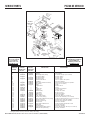
SERVICE PARTS
Models 656 & 658
PIEZAS DE SERVICIO
Modelos 656 y 658
KEY NO. MODEL 656 MODEL 658
NUMERO DE PART NO. PART NO. DESCRIPTION DESCRIPCION
CODIGO MODELO 656 MODELO 658
NO. PIEZ NO. PIEZ
1 97007383 97007383 Housing Carcasa
2 ----- 97014185 Damper Amortiguador
3 98003036 98003036 Mounting Bracket (4 Req.) Soporte de montaje (se necesitan 4)
4 99270981 ----- Receptacle, White Enchufe - Blanco
5 ----- 99270982 Receptacle, Black Enchufe - Negro
6 99270489 99270489 Receptacle, Red Enchufe - Rojo
7 ----- 99110446 Plastic Blower Wheel Disco de plástico del soplador
8 ----- 99080166 Fan Motor Motor del ventilador
9 97013628 97006987 Motor Plate / Partition Assembly Placa del motor/Conjunto del espaciador
10 ----- 99260428 Nut (4 Req.) Tuerca (se necesitan 4)
11 97013836 97013581 Grille Rejilla
12 97014211 ----- Light Reflector Reflector de luz
13 97005316 ----- Nut Tuerca
14 99770118 ----- Light Socket Casquillo de la lámpara
15 97013578 ----- Light Lens Lente de la luz
16 97005058 97005058 Bolt Assembly Conjunto de tornillos
17 ----- 99110748 Logo Button Botón con el logo
18 ----- 99150566 Grille Screw Tornillo de la parilla
19 99020290 99020290 Blower Wheel Disco del soplador
21 93260457 93260457 #10 - 32 Nut (7 Req.) Tuerca No. 10-32 (se necesitan 7)
22 99270107 99270107 Heater Hooks (5 Req.) Ganchos del calentador (se necesitan 5)
23 99150417 99150417 #8 x 1/4 Sheet Metal Screws (4 Req.)
Tornillos de lámina metálica No. 8 x 1/4 (se necesitan 4)
24 98003788 98003788 Heater Scroll Cover Cubierta de la espiral del calentador
25 97005006 97005006 Heater Scroll Housing Carcasa de la espiral del calentador
26 99080591 99080591 Heater Motor Motor del calentador
27 99170245 99170245 #8 x 3/8 Sheet Metal Screw Tornillo de lámina metálica No. 8 x 3/8
28 99160410 ----- Grille Stud Pasador de la rejilla
29 98004514 98004514 Heater Element Elemento calentador
30 99260566 99260566 Tinnerman Nut #10-32 (2 Req.) Tuerca Tinnerman No. 10 x 32 (se necesitan 2)
31 98000566 ----- Aluminum Receptacle Plug Enchufe de aluminio
Order service parts by Part No. - NOT by Key No.
Encargue piezas de servicio por No. Piez - NO por No. Codigo.
656 ONLY
SOLO PARA
EL 656
17
Replacement parts
can now be ordered
on our website.
Please visit us at
www.Broan.com
Las piezas de recambio
se pueden ahora pedir en
nuestro Web site.
Visítenos por favor en
www.Broan.com
-
 1
1
-
 2
2
-
 3
3
-
 4
4
-
 5
5
-
 6
6
-
 7
7
-
 8
8


Broan 656 Operating instructions
- Category
- Space heaters
- Type
- Operating instructions
- This manual is also suitable for
Ask a question and I''ll find the answer in the document
Finding information in a document is now easier with AI
in other languages
- español: Broan 656 Instrucciones de operación
Related papers
Other documents
-
NuTone 656 Install Manual
-
-
NuTone 765H110L Installation guide
-
NuTone QTXN110HL User manual
-
-
-
-
-
-