IMG Stage Line 25.4680 User manual
- Category
- Microphones
- Type
- User manual
This manual is also suitable for

ELECTRONICS FOR SPECIALISTS ELECTRONICS FOR SPECIALISTS ELECTRONICS FOR SPECIALISTS ELECTRONICS FOR SPECIALISTS
2,4-GHz-Taschensender
mit 2 Mikrofonen
2.4 GHz Pocket Transmitter
with 2 Microphones
TXS-2401SX
Bestell-Nr. • Order No. 25.4680
BEDIENUNGSANLEITUNG
INSTRUCTION MANUAL
MODE D’EMPLOI
ISTRUZIONI PER L’USO
MANUAL DE INSTRUCCIONES
INSTRUKCJA OBSŁUGI


3
TXS-2401SX
C
AE
8
0
6
2
4
CHANNEL
RESET
1.1. 1.1.
2.2.
1 2
5
6 9
13 14
7 8
3 4
10
1211
➀
➃
➁ ➂

4
Deutsch
English
English Page
Français
Français Page
Italiano
Italiano Pagina
Español
Español Página
Nederlands
Nederlands Pagina
Polski
Polski Strona
Deutsch
Deutsch Seite
2,4-GHz-Taschensender
Diese Bedienungsanleitung richtet sich an Be-
nutzer ohne besondere Fachkenntnisse. Bitte
lesen Sie die Anleitung vor dem Betrieb gründ-
lich durch und heben Sie sie für ein späteres
Nachlesen auf.
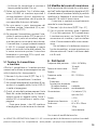
Auf der ausklappbaren Seite 3 finden Sie alle
be schriebenen Bedienelemente und Anschlüsse.
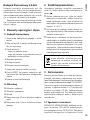
1 Übersicht der Bedienelemente
und Anschlüsse
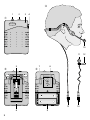
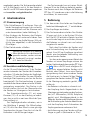
1.1 Taschensender
1 Anschlussbuchse für eines der Mikrofone
2
Ein- /Ausschalter; in der mittleren Position ist
das Mikrofon stummgeschaltet
3 Betriebsanzeige
– leuchtet im Betrieb
– blinkt bei schwachen Batterien und wäh-
rend des Geräteabgleichs
4 Lautstärkeregler
5 Gürtelklemme
6 Batteriefachdeckel
7
Drehschalter zur Wahl des Übertragungs-
kanals
8 Taster RESET zum Abgleich von Sender und
Empfänger (Neuaufbau der Funkverbindung)
9 Batterien im Batteriefach
1.2 Mikrofone
10 Kopfbügelmikrofon
11 Krawattenmikrofon
12 Befestigungsklemme
13 verriegelbarer Stecker des Kopfbügelmikro-
fons, 3,5-mm-Klinke
14 verriegelbarer Stecker des Krawattenmikro-
fons, 3,5-mm-Klinke
2 Wichtige Hinweise
fürdenGebrauch
Das Gerät entspricht allen relevanten Richtlinien
der EU und trägt deshalb das - Zeichen.
•
Das Gerät ist nur für die Verwendung im
Innenbereich geeignet. Schützen Sie es vor
Tropf- und Spritzwasser, hoher Luftfeuchtig-
keit und Hitze (zulässige Einsatztemperatur
0 – 40 °C).
•
Verwenden Sie für die Reinigung nur ein tro-
ckenes, weiches Tuch, niemals Chemikalien
oder Wasser.
•
Wird das Gerät zweckentfremdet, nicht rich-
tig angeschlossen, falsch bedient oder nicht
fachgerecht repariert, kann keine Haftung für
daraus resultierende Sach- oder Personen-
schäden und keine Garantie für das Gerät
übernommen werden.
Soll das Gerät endgültig aus dem Be-
trieb genommen werden, übergeben
Sie es zur umweltgerechten Entsor-
gung einem örtlichen Recycling betrieb.
3 Einsatzmöglichkeiten
Dieses Set, bestehend aus einem Taschensender,
einem Kopfbügelmikrofon und einem Krawat-
tenmikrofon, dient als Erweiterung des Funkmi-
krofonsystems TXS-2402SET. Die Übertragung
erfolgt digital und störungsarm auf einem von
16 wählbaren Kanälen im 2,4-GHz-Bereich. Die
Mikrofone können alternativ an den Taschen-
sender angeschlossen werden und bieten Be-
wegungsfreiheit auch bei Anwendungen, die
freie Hände erfordern.
3.1 Konformität und Zulassung
Hiermit erklärt MONACOR INTERNATIONAL, dass
sich das Gerät TXS-2401SX in Übereinstimmung
mit den grundlegenden Anforderungen und den
übrigen einschlägigen Bestimmungen der Richt-
linie 2014 / 53 / EU befindet. Die Konformitätser-
klärung kann bei MONACOR INTERNATIONAL

5
Deutsch
angefordert werden. Der Taschen sender arbeitet
im 2,4-GHz-Be reich und ist für den Betrieb in
den EU- und EFTA- Staaten allgemein zugelassen
und anmelde- und gebührenfrei.
4 Inbetriebnahme
4.1 Stromversorgung
1)
Die Gürtelklemme (5) entfernen. Dazu die
beiden Verriegelungszungen links und rechts
zusammendrücken und die Klemme nach
unten herausziehen (siehe Abbildung 2).
2)
Zum Einlegen der Batterien den Batterie-
fachdeckel (6) nach unten aufschieben. Zwei
1,5-V-Batterien der Größe Mignon (AA) pol-
richtig (wie abgebildet) in das Batteriefach
(9) einlegen.
3) Den Deckel wieder schließen.
Verbrauchte Batterien und defekte
Akkus dürfen nicht in den Hausmüll
geworfen werden, sondern müssen
als Sondermüll entsorgt werden
(z. B. beim Fachhändler).
4.2 Anschluss und Befestigung
An die 3,5-mm-Klinkenbuchse (1) des Taschen-
senders entweder den Stecker des Krawatten-
mikrofons (14) oder den Stecker des Kopfbügel-
mikrofons (13) anschließen. Die vom Mikrofon
benötigte Gleichspannung wird an der Buchse
bereitgestellt. Die Steckverbindung ist gegen
versehentliches Herausziehen mit einer Schraub-
verriegelung ausgestattet. Den Stecker in die
Buchse stecken und mit der Überwurfmutter
des Steckers im Uhrzeigersinn festschrauben.
Das Krawattenmikrofon (11) mit seiner
Klammer (12) z. B. an der Kleidung so befesti-
gen, dass es nicht zu weit vom Mund des Spre-
chers entfernt ist.
Das Kopfbügelmikrofon aufsetzen, wie in
der Abbildung 4 gezeigt. Die Mikrofonkap-
sel (10) dicht vor dem Mund in eine günstige
Sprechposition bringen. Dazu lässt sich der Mi-
krofonarm in alle Richtungen biegen.
Der Taschensender kann mit seiner Gürtel-
klemme (5) an der Kleidung befestigt werden.
Die Klemme nach dem Einlegen der Batterien
(
☞
Kap. 4.1) wieder von unten in die Halterung
einschieben, bis sie einrastet.
5 Bedienung
1)
Vor dem ersten Einschalten am Empfänger
beide Lautstärkeregler auf „1“ zurückdrehen.
2) Den Empfänger einschalten.
3)
Den Taschensender einschalten: Den Schalter
(2) ganz nach links, in die Position ON schie-
ben. Die LED (3) leuchtet im Betrieb. Leuchtet
sie nicht oder beginnt sie zu blinken, können
die Batterien zu schwach sein und müssen
ausgetauscht werden.
Nach dem Einschalten des Senders wird
eine Funkverbindung zum Empfänger auf-
gebaut. Eine LED am Empfänger signalisiert
jeweils eine bestehende Verbindung zum
entsprechenden Sender.
Vor dem ersten gemeinsamen Betrieb des
Senders mit einem Empfänger müssen die
beiden Geräte abgeglichen werden (
☞
Kapi-
tel5.1). Wenn die LED nach erfolgtem Ab-
gleich trotz eingeschalteten Senders nicht
leuchtet oder flackert, kann eine Übertra-
gungsstörung durch einen anderen Sender
die Ursache sein. In diesem Fall den Übertra-
gungskanal des Senders ändern (
☞
Kap. 5.2).
Ist die Übertragung weiterhin gestört, über-
prüfen ob
– die Batterien im Sender zu schwach sind.
– der Empfang durch Gegenstände in der
Übertragungsstrecke oder andere Funksen-
der (z. B. Mikrowellen, WLAN, Babyfone)
ge stört wird. Metallgegenstände in der
Nähe des Senders oder Empfängers können
die Richtwirkung der Antenne beeinflussen.
– sich der Empfang durch Schwenken der
Empfangsantennen verbessern lässt.
– die Entfernung zwischen Sender und Emp-
fänger zu groß ist (Reichweite ca. 20 m).

6
Deutsch
4) In das Mikrofon sprechen. Mit dem entspre-
chenden Lautstärkeregler VOLUME am Emp-
fänger die gewünschte Lautstärke einstellen.
Den Lautstärkeregler (4) am Sender nur so-
weit aufdrehen, dass der Ton nicht verzerrt
wiedergegeben wird.
5) Zum kurzzeitigen Stummschalten des Mikro-
fons den Schalter (2) in die mittlere Position
(ST.BY) stellen.
6)
Zum Ausschalten des Senders den Schalter in
die rechte Position OFF schieben. Wird länger
als 5 Minuten nicht in das Mikrofon gespro-
chen oder ist es so lange stummgeschaltet,
schaltet sich der Sender automatisch aus [die
LED (3) erlischt] und vermeidet so unnötigen
Batterieverbrauch. Zum Wiedereinschalten
den Schalter kurz in die Position OFF und
wieder in die Position ON schieben.
5.1 Abgleichen von Sender und
Empfänger
Damit Sender und Empfänger kommunizieren
können, müssen die beiden Geräte einmalig
miteinander abgeglichen werden.
1)
Die Gürtelklemme (5) entfernen (
☞
Kapi-
tel4.1).
2) Sender und Empfänger einschalten.
3)
Am Sender die Reset-Taste (8) mit einem
dünnen Gegenstand drücken, bis die LED (3)
blinkt.
4)
Anschließend auf der Rückseite des Emp-
fängers die Reset-Taste des gewünschten
Empfangskanals mit einem dünnen Gegen-
stand drücken, bis die entsprechende Verbin-
dungs-LED blinkt.
Nach kurzer Zeit hören beide LEDs auf zu
blinken, die Verbindung ist hergestellt.
5.2 Ändern des Übertragungskanals
Wird die Übertragung durch ein anderes Gerät
gestört [Tonaussetzer treten auf oder die Ver-
bindungs-LED am Empfänger flackert], kann die
Sendefrequenz geändert werden. Es stehen 16
Übertragungskanäle zur Auswahl.
Der Empfänger stellt sich jeweils automa-
tisch auf die neue Frequenz um.
1)
Die Gürtelklemme (5) entfernen (
☞
Kap.4.1).
2)
Mit einem kleinen Schraubendreher den
Drehschalter (7) in eine andere Position dre-
hen. Bei eingeschaltetem Sender und Emp-
fänger kann mithilfe der Verbindungs-LED
am Empfänger die neue Verbindung sofort
kontrolliert werden.
Um eine gegenseitige Störung zweier
Sender auszuschließen, muss ein Mindest-
abstand von 2 Kanälen eingestellt werden.
Der ideale Abstand beträgt 8 Kanäle.
6 Technische Daten
Trägerfrequenzbereich: . . . 2404 – 2476 MHz,
16Kanäle
Sendeleistung: . . . . . . . . . 10 mW
Reichweite: . . . . . . . . . . . . 20 m
Audiofrequenzbereich: . . . 80 – 12 000 Hz
Mikrofone
Wandlertyp: . . . . . . . . . Elektret
Richtcharakteristik
Kopfbügel mikrofon: . . Niere
Krawatten mikrofon: . . Kugel
Stromversorgung: . . . . . . . 2 × 1,5-V-Batterie,
Typ Mignon (AA)
Betriebsdauer: . . . . . . . . . . > 20 h
Einsatztemperatur: . . . . . . 0 – 40 °C
Abmessungen: . . . . . . . . . 62 × 90 × 28 mm
Gewicht: . . . . . . . . . . . . . . 105 g
(ohne Batterien)
Änderungen vorbehalten.
Diese Bedienungsanleitung ist urheberrechtlich für MONACOR
®
INTERNATIONAL GmbH & Co. KG geschützt.
Eine Reproduktion für eigene kommerzielle Zwecke – auch auszugsweise – ist untersagt.

7
English
Italiano
Italiano Pagina
Español
Español Página
Polski
Polski Strona
2.4 GHz Pocket Transmitter
These instructions are intended for users without
any specific technical knowledge. Please read
these instructions carefully prior to operating the
unit and keep them for later reference.
All operating elements and connections
described can be found on the fold-out page 3.
1 Operating Elements and
Connections
1.1 Pocket Transmitter
1
Connection jack for one of the microphones
2
On / off switch; in mid-position, the micro-
phone is muted
3 Power LED
– lights up during operation
– starts flashing when the batteries are low
and while the units are being matched
4 Volume control
5 Belt clip
6 Cover of battery compartment
7 Selector switch for the transmission channel
8
Momentary pushbutton RESET to match the
transmitter and the rceiver (to establish a
new wireless connection)
9 Batteries in the battery compartment
1.2 Microphones
10 Headband microphone
11 Tie clip microphone
12 Clip
13 Locking plug of the headband microphone,
3.5 mm plug
14
Locking plug of the tie clip microphone,
3.5 mm plug
2 Important Notes
The unit corresponds to all relevant directives of
the EU and is therefore marked with .
•
The unit is suitable for indoor use only. Protect
it against dripping water and splash water,
high air humidity and heat (admissible ambi-
ent temperature range 0 – 40 °C).
•
For cleaning only use a dry, soft cloth; never
use water or chemicals.
•
No guarantee claims for the unit and no liabil-
ity for any resulting personal damage or mate-
rial damage will be accepted if the unit is used
for other purposes than originally intended, if
it is not correctly connected or operated, or if
it is not repaired in an expert way.
If the unit is to be put out of operation
definitively, take it to a local recycling
plant for a disposal which is not harm
-
ful to the environment.
3 Applications
This set combines a pocket transmitter, a head-
band microphone and a tie clip microphone and
is used to extend the wireless microphone sys-
tem TXS-2402SET. The digital transmission with
high resistance to interference is made on one
of 16 channels available in the 2.4 GHz range.
Alternatively connect the microphones to the
pocket transmitter. This is ideally suited for any
hands-free applications.
3.1 Conformity and approval
Herewith, MONACOR INTERNATIONAL declare
that the unit TXS-2401SX is in accordance with
the basic requirements and the other relevant
regulations of the directive 2014 / 53 / EU. The
declaration of conformity can be requested from
MONACOR INTERNATIONAL. The pocket trans-
mitter operates in the 2.4 GHz range. It is licence-
free and generally approved for operation in EU
and EFTA countries.
English
English Page

8
English
4 Setting into Operation
4.1 Power supply
1) Remove the belt clip (5): Press together the
securing lugs on the left and on the right
and push the clip downwards to remove it
(see figure 2).
2) To insert the batteries, slide down the cover
(6) to open the battery compartment. Insert
two 1.5 V batteries of size AA into the com-
partment (9) with the positive and negative
poles as indicated.
3) Replace the cover.
Never put discharged batteries or
defective rechargeable batteries in
the household waste; always take
them to a special waste disposal,
e. g. collection container at your
retailer.
4.2 Connection and attachment
Connect the plug of the tie clip microphone (14)
or the plug of the headband microphone (13) to
the 3.5 mm jack (1) of the pocket transmitter.
The DC voltage required by the microphone is
available at this jack. The connector is provided
with a locking mechanism to prevent accidental
disconnection. Connect the plug to the jack and
turn the nut clockwise to secure the plug.
Attach the tie clip microphone (11) with its
clip (12) (e. g. to your clothes) so that it is close
to your mouth.
Put on the headband microphone accord-
ing to figure 4. Place the microphone cartridge
(10) close to your mouth in a good position for
talking. The microphone arm will bend in any
direction.
Use the belt clip (5) to attach the pocket
transmitter to your clothes. After inserting the
batteries (
☞
chapter 4.1), slide the clip from
the bottom into the support until it engages.
5 Operation
1) Before initial operation, turn back both vol-
ume controls on the receiver to “1”.
2) Switch on the receiver.
3)
Switch on the pocket transmitter: Set the
switch (2) to the left stop (position ON): The
LED (3) lights up during operation. If it fails
to light up or if it starts flashing, the batteries
may be low and should be replaced.
After switching on the transmitter, a wire-
less connection to the receiver is made. An
LED on the receiver will indicate successful
connection to the corresponding transmitter.
Before operating the transmitter together
with a receiver for the first time, match the
two units (
☞
chapter 5.1). If the LED fails to
light up or starts flickering although match-
ing has been successful and the transmitter
has been switched on, another transmitter
may cause interference in transmission. In this
case, change the transmission channel of the
transmitter (
☞
chapter 5.2).
If there is still interference in transmission,
please check
– if the batteries of the transmitter are low.
– if there are objects or other wireless trans-
mitters (e. g. microwaves, WLAN, baby
monitors) in the transmission path which
may interfere with reception. Metal objects
in the vicinity of the transmitter or receiver
may affect the directivity of the antenna.
– if the reception can be improved when you
turn the antennas.
– if the distance between the transmitter
and the receiver is too long (range: approx.
20 m).
4)
Speak into the microphone. Adjust the de-
sired volume with the corresponding VOLUME
control on the receiver. Turn up the volume
control (4) on the transmitter without distort-
ing the sound.

9
English
5)
To briefly mute the microphone, set the
switch (2) to mid-position (ST.BY).
6) To switch off the transmitter, set the switch
to the right stop (position OFF). To avoid un-
necessary battery consumption, the transmit-
ter will switch off [LED (3) off] automatically
after 5minutes when nobody speaks into the
microphone or when the microphone is
muted. To switch the transmitter on again,
briefly set the switch to OFF and then to ON
again.
5.1 Matching the transmitter
andthereceiver
To enable communication between the transmit-
ter and the receiver, match the two units once.
1) Remove the belt clip (5) [
☞
chapter 4.1].
2) Switch on the transmitter and the receiver.
3)
Use a thin object to press the pushbutton
RESET (8) on the transmitter until the LED (3)
starts flashing.
4) Then use a thin object to press the pushbut-
ton RESET of the desired reception channel on
the rear of the receiver until the correspond-
ing connection LED starts flashing.
After a short while, both LEDs stop flash-
ing to indicate that connection has been
made.
5.2 Changing the transmission channel
If another unit interferes with the transmission
[there are sound interruptions or the connec-
tion LED on the receiver keeps flickering], it is
possible to change the transmission frequency.
16transmission channels are available.
The receiver will automatically change to
the new frequency.
1) Remove the belt clip (5) [
☞
chapter 4.1].
2)
Use a small screwdriver to set the selector
switch (7) to a different position. When the
transmitter and the receiver are switched on,
the new connection can be checked imme-
diately by means of the connection LED on
the receiver.
To prevent mutual interference of two
transmitters, observe a minimum distance of
2channels. The ideal distance is 8 channels.
6 Specifications
Carrier frequency range: . . . 2404 – 2476 MHz,
16channels
Transmitting power: . . . . . . 10 mW
Range: . . . . . . . . . . . . . . . . 20 m
Audio frequency range: . . . 80 – 12 000 Hz
Microphones
Type of transducer: . . . . . electret
Directivity
Headband microphone: cardioid
Tie clip microphone: . . . omnidirectional
Power supply: . . . . . . . . . . . 2 × 1.5 V battery,
sizeAA
Operating time: . . . . . . . . . > 20 h
Ambient temperature: . . . . 0 – 40 °C
Dimensions: . . . . . . . . . . . . 62 × 90 × 28 mm
Weight: . . . . . . . . . . . . . . . 105 g
(without batteries)
Subject to technical modification.
All rights reserved by MONACOR
®
INTERNATIONAL GmbH & Co. KG. No part of this instruction manual may
be reproduced in any form or by any means for any commercial use.

10
Français
Deutsch
Deutsch Seite
English
English Page
Italiano
Italiano Pagina
Español
Español Página
Nederlands
Nederlands Pagina
Polski
Polski Strona
Emetteur de poche 2,4 GHz
Cette notice s’adresse aux utilisateurs sans
connaissances techniques particulières. Veuillez
lire la présente notice avant le fonctionnement
et conservez-la pour pouvoir vous y reporter
ultérieurement.
Vous trouverez sur la page 3, dépliable, les
éléments et branchements décrits.
1 Eléments et branchements
1.1 Emetteur de poche
1 Prise de branchement pour un des micros
2 Interrupteur marche / arrêt : en position mé-
diane, le son du micro est coupé
3 Témoin de fonctionnement
– brille pendant le fonctionnement
– clignote en cas de batteries faibles et pen-
dant l’appairage des appareils
4 Réglage de volume
5 Clip de ceinture
6 Couvercle compartiment batterie
7
Sélecteur rotatif pour sélectionner le canal
de transmission
8 Touche RESET pour appairer le récepteur et
l’émetteur (rétablissement de la connexion
radio)
9 Batteries dans le compartiment batterie
1.2 Microphones
10 Micro serre-tête
11 Micro cravate
12 Pince de fixation
13
Fiche verrouillable du micro serre-tête,
jack3,5
14
Fiche verrouillable du micro cravate, jack 3,5
2 Conseils importants
d’utilisation
L’appareil répond à toutes les directives néces-
saires de l’Union européenne et porte donc le
symbole .
•
L’appareil n’est conçu que pour une utilisa-
tion en intérieur. Protégez-le de tout type de
projections d’eau, des éclaboussures, d’une
humidité de l’air élevée et de la chaleur (plage
de température de fonctionnement autori
-
sée: 0 – 40 °C).
•
Pour le nettoyer, utilisez uniquement un chif-
fon sec et doux, en aucun cas de produits
chimiques ou d’eau.
•
Nous déclinons toute responsabilité en cas de
dommages matériels ou corporels si l’appareil
est utilisé dans un but autre que celui pour le-
quel il a été conçu, s’il n’est pas correctement
branché ou utilisé ou s’il n’est pas réparé par
un technicien habilité ; en outre, la garantie
deviendrait caduque.
Lorsque l'appareil est définitivement
retiré du service, vous devez le déposer
dans une usine de recyclage de proxi-
mité pour contribuer à son élimination
non polluante.
CARTONS ET EMBALLAGE
PAPIER À TRIER
3 Possibilités d’utilisation
Cet ensemble composé d’un émetteur de poche,
d’un micro serre-tête et d’un micro cravate
permet de compléter le système micro sans fil
TXS-2402SET. La transmission des signaux micro
s’effectue en digital et avec un minimum d’inter-
férences sur 1 des 16 canaux disponibles dans
la plage 2,4 GHz. Les microphones peuvent être
reliés en alternance à l’émetteur de poche, pro-
posant ainsi une grande liberté de mouvement
même pour des applications nécessitant d’avoir
les mains libres.
Français
Français Page

11
Français
3.1 Conformité et autorisation
Par la présente, MONACOR INTERNATIONAL
déclare que l’appareil TXS-2401SX se trouve
en conformité avec les exigences fondamen-
tales et les autres réglementations inhérentes
à la directive 2014 / 53 / UE. La déclaration de
conformité peut être demandée auprès de
MONACOR INTERNATIONAL. L’émetteur de
poche fonctionne dans la plage 2,4 GHz et est
autorisé pour un fonctionnement dans les pays
de l’Union européenne et de l’A.E.L.E. sans dé-
claration et gratuitement.
4 Fonctionnement
4.1 Alimentation
1)
Retirez le clip de ceinture (5). Appuyez sur les
deux languettes de verrouillage à gauche et
à droite et poussez la pince vers le bas (voir
schéma 2).
2)
Pour insérer les batteries, poussez le couvercle
du compartiment batterie (6) vers le bas et
insérez deux piles 1,5 V de type R6 dans le
compartiment (9) en respectant la polarité
(voir schéma).
3) Refermez le couvercle.
Ne jetez pas les batteries usagés ou
les accumulateurs défectueux dans
la poubelle domestique ; déposez-les
dans un container spécifique ou ra-
menez-les à votre détaillant.
4.2 Branchement et fixation
Reliez à la prise jack 3,5 (1) de l’émetteur de
poche soit la fiche du micro cravate (14) soit celle
du micro serre-tête (13). La tension continue
nécessaire pour le micro est disponible à la prise.
La connexion est dotée d’un verrouillage à vis
pour éviter tout débranchement accidentel. Met
-
tez la fiche dans la prise et vissez avec l’écrou
dans le sens des aiguilles d’une montre.
Fixez le micro cravate (11) avec sa pince (12)
par exemple sur le vêtement de telle sorte qu’il
ne soit pas trop loin de la bouche.
Placez le micro serre-tête comme indiqué sur
le schéma 4. Mettez la capsule micro (10) près
de la bouche dans une position favorable pour
parler. Vous pouvez plier le bras de micro dans
toutes les directions.
Vous pouvez fixer l’émetteur de poche via
son clip de ceinture (5) sur un vêtement. Une fois
les batteries insérées (
☞
chapitre 4.1), insérez
la pince dans le support par le bas et poussez-la
vers le haut jusqu’à ce qu’elle s’enclenche.
5 Utilisation
1)
Avant la première mise en service, tournez
les deux réglages de volume sur le récepteur
sur «1».
2) Allumez le récepteur.
3) Allumez l’émetteur de poche : poussez l’in-
terrupteur (2) à gauche sur la position ON. La
LED (3) brille pendant le fonctionnement. Si
elle ne brille pas ou si elle commence à cligno-
ter, les batteries sont trop faibles et doivent
être remplacées.
Une fois l’émetteur allumé, une connexion
radio avec le récepteur est établie. Une LED
sur le récepteur indique la connexion vers
l’émetteur correspondant.
Avant le premier fonctionnement de
l’émetteur avec le récepteur, il faut que
les deux appareils soient appairés (
☞
cha-
pitre5.1). Lorsque la LED, une fois les appa-
reils appairés et l’émetteur allumé, ne brille
pas ou scintille, il peut y avoir une perturba-
tion dans la transmission causée par un autre
émetteur. Dans ce cas, modifiez le canal de
transmission de l’émetteur (
☞
chapitre 5.2).
Si la transmission continue à être perturbée,
vérifiez si :
– les batteries de l’émetteur sont trop faibles.
– la réception est perturbée par des objets se
trouvant dans la voie de transmission ou par
d’autres émetteurs radio (par exemple mi-
cro-ondes, WLAN, babyphones). Des objets
métalliques à proximité de l’émetteur ou du

12
Français
récepteur peuvent influencer la directivité
de l’antenne.
– la réception peut être améliorée en tournant
les antennes.
– la distance entre l’émetteur et le récepteur
est trop importante (portée: 20 m environ).
4) Parlez dans le micro. Réglez le volume sou-
haité sur le récepteur avec le réglage VOLUME
correspondant. Tournez le réglage de volume
(4) sur l’émetteur jusqu’à ce que le son ne
soit pas distordu.
5)
Pour couper brièvement le son du micro, met-
tez l’interrupteur (2) sur la position médiane
(ST.BY).
6)
Pour éteindre l’émetteur, mettez l’interrupteur
sur la position droite OFF. Si vous ne parlez
pas pendant plus de 5 minutes dans le micro,
ou s’il est coupé pendant plus de 5minutes,
l’émetteur se coupe automatiquement [la LED
(3) s’éteint], évitant ainsi toute consommation
inutile de la batterie. Pour rallumer, mettez
brièvement l’interrupteur sur la position OFF
et remettez-le sur la position ON.
5.1 Appairage de l’émetteur et
durécepteur
Pour que l’émetteur et le récepteur puissent
communiquer, il faut que les deux appareils
soient appairés ensemble une fois.
1)
Retirez le clip de ceinture (5) [
☞
chapitre 4.1].
2) Allumez l’émetteur et le récepteur.
3) Sur l‘émetteur, appuyez sur la touche Reset
(8) avec un objet fin jusqu‘à ce que la LED
(3) clignote.
4) Ensuite, sur la face arrière du récepteur ap-
puyez sur la touche Reset du canal de récep-
tion souhaité avec un objet fin jusqu’à ce que
la LED de connexion correspondante clignote.
Peu de temps après, les deux LEDs ne cli-
gnotent plus, la connexion est établie.
5.2 Modification du canal
detransmission
Si la transmission est perturbée par un autre
appareil [interruptions de son ou la LED de
connexion sur le récepteur scintille], on peut
modifier la fréquence d’émission. 16 canaux de
transmissions sont disponibles.
Le récepteur commute automatiquement
sur la nouvelle fréquence.
1)
Retirez le clip de ceinture (5) [
☞
chapitre 4.1].
2) Avec un petit tournevis, tournez le sélecteur
(7) dans une autre position. Si l’émetteur et
le récepteur sont allumés, on peut contrôler
immédiatement la nouvelle connexion avec la
LED de connexion sur le récepteur.
Pour éviter toute perturbation mutuelle
entre deux émetteurs, il faut une distance mi-
nimale de deux canaux, l’idéal étant 8 canaux.
6 Caractéristiques techniques
Plage de fréquences
porteuses : . . . . . . . . . . . . 2404 – 2476 MHz,
16canaux
Puissance émission : . . . . . 10 mW
Portée : . . . . . . . . . . . . . . . 20 m
Plage de fréquences audio :
80 – 12 000 Hz
Microphones
Type convertisseur : . . . . électret
Caractéristique
de directivité
Micro serre-tête : . . . . cardioïde
Micro cravate : . . . . . . omnidirectionnel
Alimentation : . . . . . . . . . . 2 × batterie 1,5 V,
type R6
Durée de fonctionnement : > 20 h
Température fonc. : . . . . . . 0 – 40 °C
Dimensions : . . . . . . . . . . . 62 × 90 × 28 mm
Poids : . . . . . . . . . . . . . . . . 105 g (sans batteries)
Tout droit de modification réservé.
Notice d’utilisation protégée par le copyright de MONACOR
®
INTERNATIONAL GmbH & Co. KG. Toute repro-
duction même partielle à des fins commerciales est interdite.

13
Italiano
Español
Español Página
Polski
Polski Strona
Trasmettitore 2,4 GHz
Queste istruzioni sono rivolte all‘utente senza
conoscenze tecniche specifiche. Vi preghiamo
di leggerle attentamente prima della messa in
funzione e di conservarle per un uso futuro.
A pagina 3, se aperta completamente,
vedrete gli elementi di comando e i collegamenti
descritti.
1 Elementi di comando e
collegamenti
1.1 Trasmettitore tascabile
1 Presa di connessione per uno dei microfoni
2 Interruttore on / off; in posizione centrale, il
microfono è messo in muto
3 Spia di funzionamento
– accesa durante il funzionamento
– lampeggia con batterie deboli e durante la
taratura fra gli apparecchi
4 Regolatore volume
5 Clip da cintura
6 Coperchio del vano batterie
7 Selettore per il canale di trasmissione
8
Pulsante RESET per l’adattamento fra tra-
smettitore e ricevitore (nuova istaurazione
di un collegamento via radio)
9 Batterie nel vano batterie
1.2 Microfoni
10 Microfono headset
11 Microfono a cravatta
12 Clip di fissaggio
13 Connettore bloccabile del microfono head-
set, jack 3,5 mm
14 Connettore bloccabile del microfono a cra-
vatta, jack 3,5 mm
2 Avvertenze importanti perl’uso
L’apparecchio è conforme a tutte le direttive rile
-
vanti dell’UE e pertanto porta la sigla .
•
Usare l’apparecchio solo all’interno di locali
e proteggerlo dall’acqua gocciolante e dagli
spruzzi d’acqua, da alta umidità dell’aria e
dal calore (temperatura d’impiego ammessa
fra 0 e 40 °C).
•
Per la pulizia usare solo un panno morbido,
asciutto; non impiegare in nessun caso acqua
o prodotti chimici.
•
Nel caso d’uso improprio, di collegamenti sba
-
gliati, d’impiego scorretto o di riparazione
non a regola d’arte dell’apparecchio, non si
assume nessuna responsabilità per eventuali
danni consequenziali a persone o a cose e non
si assume nessuna garanzia per l’apparecchio.
Se si desidera eliminare l’apparecchio
definitivamente, consegnarlo per lo
smaltimento ad un’istituzione locale
per il riciclaggio.
3 Possibilità d’impiego
Il presente set, composto da un trasmettitore
tascabile, un microfono headset e un micro-
fono a cravatta, serve come integrazione del
sistema di radiomicrofoni TXS-2402SET. La tra-
smissione avviene in modo digitale e con inter-
ferenze ridotte su uno fra i 16 canali disponibili
nel settore 2,4 GHz. I microfoni possono essere
collegati in alternativa con il trasmettitore tasca-
bile e offrono libertà di movimento anche nelle
applicazioni che richiedono mani libere.
3.1 Conformità e omologazione
La MONACOR INTERNATIONAL dichiara che
l’apparecchio TXS-2401SX è conforme a tutti i
requisiti di base e alle rimanenti disposizioni in
materia della direttiva 2014 / 53 / UE. La dichia-
razione di conformità può essere richiesta a
MONACOR INTERNATIONAL. Il trasmetti-
tore tascabile lavora nel settore 2,4 GHz ed è
Italiano
Italiano Pagina

14
Italiano
omologato per l’impiego negli stati dell’UE e
dell’EFTA e non richiede né registrazione né
pagamento di tasse.
4 Messa in funzione
4.1 Alimentazione
1)
Staccare il clip da cintura (5), premendo le due
linguette di bloccaggio a destra e a sinistra
verso il centro e sfilare il clip verso il basso
(vedi illustrazione 2).
2) Per inserire le batterie, aprire il coperchio del
vano batterie (6) verso il basso. Inserire nel
vano batterie (9) due batterie 1,5 V del tipo
stilo (AA) con la polarità corretta (vedi illu-
strazione).
3) Richiudere il coperchio.
Non gettare le batterie scariche o
difettose nelle immondizie di casa
bensì negli appositi contenitori
(p. es. presso il vostro rivenditore).
4.2 Collegamento e fissaggio
Alla presa jack 3,5 mm (1) del trasmettitore ta-
scabile collegare il connettore del microfono a
cravatta (14) o del microfono headset (13). La
tensione continua richiesta per il microfono è
disponibile alla presa. La connessione dispone di
un blocco per escludere lo distacco involontario.
Inserire il connettore nella presa e avvitarlo in
senso orario per mezzo del dado di accoppia-
mento.
Con il suo clip (12), fissare il microfono a
cravatta (11) p. es. ai vestiti in modo che non
sia troppo lontano dalla bocca del portatore.
Sistemare il microfono headset sulla testa
come indicato nell’illustrazione. Portare la cap-
sula del microfono (10) proprio davanti alla
bocca in una posizione adatta per parlare. A
tale scopo, il braccio del microfono può essere
piegato in tutte le direzioni.
Il trasmettitore tascabile può essere fissato ai
vestiti per mezzo del suo clip da cintura (5). Dopo
aver montato le batterie (
☞
Cap. 4.1), inserire
il clip dal basso nella sua sede fino allo scatto.
5 Funzionamento
1) Prima della prima accensione, portare i due
regolatori volume del ricevitore su “1”.
2) Accendere il ricevitore.
3)
Accendere il trasmettitore tascabile: Spostare
l’interruttore (2) tutto a sinistra in posizione
ON. Il LED (3) è acceso durante il funziona-
mento. Se non si accende e se inizia a lam-
peggiare, le batterie possono essere deboli e
devono essere sostituite.
Dopo l’accensione del trasmettitore s’in-
staura un collegamento via radio con il rice-
vitore. Un LED sul ricevitore segnala una con-
nessione esistente con il relativo trasmettitore.
Prima del primo impiego del trasmettitore
con un ricevitore, occorre tarare i due appa-
recchi (
☞
Cap. 5.1). Se dopo la taratura e
nonostante il trasmettitore sia acceso, il LED
non rimane accesso o se sfarfalla, la causa ne
può essere l‘interferenza nella trasmissione
proveniente da un altro trasmettitore. In que-
sto caso cambiare il canale di trasmissione del
trasmettitore (
☞
Cap. 5.2).
Se la trasmissione continua ad essere distur-
bata, controllare se
– le batterie nel trasmettitore sono troppo
deboli;
– la ricezione è compromessa da oggetti che
si trovano fra trasmettitore e ricevitore o
da altri radiotrasmettitori (p. es. microonde,
WLAN, babyphone). Oggetti metallici vicini
al trasmettitore o al ricevitore possonjo in-
fluenzare l’effetto dell’antenna;
– la ricezione migliora spostando le antenne
di ricezione;

15
Italiano
– la distanza fra trasmettitore e ricevitore è
troppo grande (portata 20 m ca.).
4)
Parlare nel microfono. Con il relativo rego-
latore VOLUME sul ricevitore impostare il
volume desiderato. Aprire il regolatore vo-
lume (4) del trasmettitore solo al punto da
non avere delle distorsioni dell’audio.
5)
Per una messa in muto temporanea del
microfono, portare l’interruttore (2) in posi-
zione centrale (ST.BY).
6)
Per spegnere il trasmettitore, spostare l’inter-
ruttore in posizione destra OFF. Se per più di
5 minuti non si parla nel microfono, oppure
se è stato messo in muto per la stessa durata,
il trasmettitore si spegne automaticamente
[il LED (3) si spegne] escludendo in questo
modo un consumo inutile delle batterie. Per
la nuova accensione spostare l’interruttore
brevemente in posizione OFF e quindi nuo-
vamente in posizione ON.
5.1 Taratura fra trasmettitore
ericevitore
Affinché il trasmettitore e il ricevitore possano
comunicare fra di loro, occorre eseguire una sola
volta la taratura fra i due apparecchi.
1) Staccare il clip da cintura (5) [
☞
Cap. 4.1].
2) Accendere il trasmettitore e il ricevitore.
3)
Sul trasmettitore premere il tasto Reset (8) ser-
vendosi di un oggetto sottile, finché il LED(3)
si mette a lampeggiare.
4)
Quindi, sul retro del ricevitore premere il tasto
Reset del canale desiderato per la ricezione,
sempre usando un oggetto sottile, finché il
relativo LED di connessione si metta a lam-
peggiare.
Dopo poco tempo, i due LED smettono
a lampeggiare e la connessione è instaurata.
5.2 Modifica del canale di trasmissione
Se la trasmissione è disturbata da un altro appa-
recchio [l’audio è parzialmente interrotto o il LED
di connessione sul ricevitore sfarfalla], è possibile
modificare la frequenza di trasmissione. Sono
disponibili 16 canali di trasmissione.
Il ricevitore si regolerà automaticamente
secondo la nuova frequenza.
1) Staccare il clip da cintura (5) [
☞
Cap. 4.1[.
2) Con un piccolo cacciavite, girare il selettore
(7) in un’altra posizione. Se il trasmettitore e
il ricevitore sono accesi, con l’aiuto del LED di
connessione sul ricevitore, si può controllare
subito il funzionamento della nuova connes-
sione.
Per escludere un’interferenza reciproca
fra due trasmettitori, occorre impostare una
distanza minima di 2 canali. La distanza ideale
e di 8 canali.
6 Dati tecnici
Frequenze della portante: . . 2404 – 2476 MHz,
16 canali
Potenza di trasmissione: . . . 10 mW
Portata: . . . . . . . . . . . . . . . . 20 m
Frequenze audio: . . . . . . . . 80 – 12 000 Hz
Microfoni
Trasduttore: . . . . . . . . . . . electret
Caratteristica direzionale
Microfono headset: . . . cardioide
Microfono a cravatta: . . onnidirezionale
Alimentazione: . . . . . . . . . . 2 × batterie 1,5 V,
tipo stilo (AA)
Durata: . . . . . . . . . . . . . . . . > 20 h
Temperatura d’esercizio: . . . 0 – 40 °C
Dimensioni: . . . . . . . . . . . . . 62 × 90 × 28 mm
Peso: . . . . . . . . . . . . . . . . . . 105 g
(senza batterie)
Con riserva di modifiche tecniche.
La MONACOR
®
INTERNATIONAL GmbH & Co. KG si riserva ogni diritto di elaborazione in qualsiasi forma delle
presenti istruzioni per l’uso. La riproduzione – anche parziale – per propri scopi commerciali è vietata.

16
Español
Deutsch
Deutsch Seite
English
English Page
Français
Français Page
Italiano
Italiano Pagina
Nederlands
Nederlands Pagina
Polski
Polski Strona
Español
Español Página
Emisor de Petaca 2,4 GHz
Estas instrucciones van dirigidas a usuarios sin
ningún conocimiento técnico específico. Lea
atentamente estas instrucciones antes de utili-
zar el aparato y guárdelas para usos posteriores.
Puede encontrar todos los elementos de
funcionamiento y las conexiones que se descri-
ben en la página 3 desplegable.
1 Elementos de Funcionamiento
y Conexiones
1.1 Emisor de petaca
1
Toma de conexión para uno de los micró-
fonos
2 Interruptor ON / OFF; en la posición interme-
dia el micrófono queda silenciado
3 LED POWER
– Se ilumina durante el funcionamiento
– Empieza a parpadear cuando las baterías
están bajas y cuando los aparatos están
emparejados
4 Control de volumen
5 Pinza de cinturón
6 Tapa del compartimento de la batería
7
Interruptor selector para el canal de trans-
misión
8 Pulsador RESET para emparejar el emisor y
el receptor (para crear una conexión inalám-
brica nueva)
9 Baterías en el compartimento de la batería
1.2 Micrófonos
10 Micrófono de cabeza
11 Micrófono de solapa
12 Pinza
13 Conector de bloqueo para el micrófono de
cabeza, conector jack 3,5 mm
14 Conector de bloqueo para el micrófono de
solapa, conector jack 3,5 mm
2 Notas Importantes
El aparato cumple con todas las directivas rele-
vantes de la UE y por lo tanto está marcado con
el símbolo .
•
El aparato está adecuado sólo para utilizarlo
en interiores. Protéjalo de goteos y salpicadu-
ras, elevada humedad del aire y calor (tempe-
ratura ambiente admisible: 0 – 40 ºC).
•
Utilice sólo un paño suave y seco para la lim-
pieza; no utilice nunca ni agua ni productos
químicos.
•
No podrá reclamarse garantía o responsa-
bilidad alguna por cualquier daño personal
o material resultante si el aparato se utiliza
para otros fines diferentes a los originalmente
concebidos, si no se conecta o se utiliza ade-
cuadamente o si no se repara por expertos.
Si va a poner el aparato definitiva-
mente fuera de servicio, llévelo a la
planta de reciclaje más cercana para
que su eliminación no sea perjudicial
para el medioambiente.
3 Aplicaciones
Este conjunto combina un emisor de petaca, un
micrófono de cabeza y un micrófono de solapa
y se utiliza para ampliar el sistema de micrófono
inalámbrico TXS-2402SET. La transmisión digital
con una gran resistencia a las interferencias se
realiza en uno de los 16 canales disponibles en
el rango de 2,4 GHz. Alternativamente conecte
los micrófonos al emisor de petaca. Este está
adecuado especialmente para aplicaciones de
manos libres.
3.1 Conformidad y aprobación
Por la presente, MONACOR INTERNATIONAL
declara que el aparato TXS-2401SX cumple
con los requisitos básicos y las demás regula-
ciones relevantes de la directiva 2014 / 53 / UE. Se
puede solicitar la declaración de conformidad a
MONACOR INTERNATIONAL. El emisor de

17
Español
petaca funciona en el rango de 2,4 GHz, no
requiere ninguna licencia y está aprobado
para el funcionamiento en la UE y en los países
de la AELC.
4 Puesta en Marcha
4.1 Alimentación
1)
Extraiga la pinza de cinturón (5): Pulse a la vez
los terminales de seguridad de la izquierda y
de la derecha y pulse la pinza hacia abajo para
extraerla (ver figura 2).
2) Para insertar las baterías, deslice hacia abajo
la tapa (6) para abrir el compartimento de la
batería. Inserte 2 baterías de 1,5 V tipo AA en
el compartimento (9) con los polos positivo y
negativo como se indica.
3) Coloque la tapa de nuevo.
Las baterías gastadas o las bate-
rías recargables defectuosas no
deben depositarse en el contene-
dor normal; llévelas a un contene-
dor especial (p. ej. contenedor de
su vendedor).
4.2 Conexión y Acoplamiento
Conecte el conector del micrófono de solapa
(14) o el conector del micrófono de cabeza (13)
a la toma jack 3,5 mm (1) del emisor de petaca.
El voltaje DC que necesita el micrófono está dis-
ponible en esta toma. El conector está provisto
con mecanismo de bloqueo para prevenir la
desconexión accidental. Conecte el conector a
la toma y gire la tuerca en sentido horario para
asegurar el conector.
Fije el micrófono de solapa (11) con su pinza
(12) p. ej. en su ropa de modo que quede cerca
de su boca.
Ponga el micrófono de cabeza tal y como se
muestra en la figura 4. Coloque la cápsula de mi-
crófono (10) cerca de su boca y en una posición
que favorezca el habla. El brazo del micrófono
se puede doblar en cualquier dirección.
Utilice la pinza de cinturón (5) para fijar el
emisor de petaca en su ropa. Después de insertar
las baterías (
☞
apartado 4.1) deslice la pinza
desde abajo en el soporte hasta que encaje.
5 Funcionamiento
1)
Antes del primer funcionamiento, baje los
dos controles de volumen del receptor a “1”.
2) Conecte el receptor.
3) Conecte el emisor de petaca: Ajuste el inter-
ruptor (2) en el tope izquierdo (posición
ON): El LED (3) se ilumina durante el funcio-
namiento. Si no se ilumina o si empieza a
parpadear, puede que las baterías se estén
agotando y tenga que cambiarlas.
Después de conectar el emisor, se creará
una conexión inalámbrica con el receptor. Un
LED en el receptor indicará la correcta cone-
xión con el emisor correspondiente.
Antes de utilizar el emisor junto con un
receptor por primera vez, empareje los dos
aparatos (
☞
apartado 5.1). Si el LED no se ilu-
mina o empieza a parpadear incluso después
del emparejamiento correcto y con el emisor
conectado, puede que otro emisor esté pro-
vocando interferencias en la transmisión. En
este caso, cambie el canal de transmisión del
emisor (
☞
apartado 5.2).
Si todavía aparecen interferencias en la trans-
misión, compruebe si:
– Las baterías del emisor se están agotando.
– Hay objetos u otros emisores inalámbricos
(p. ej. microondas, WLAN, monitores de
bebé) en la vía de transmisión que puedan
interferir con la recepción. Los objetos me-
tálicos cerca del emisor o del receptor pue-
den afectar la direccionalidad de la antena.
– La recepción mejora cuando mueve las an-
tenas.
– La distancia entre el emisor y el receptor
es demasiado grande (rango: 20 m aprox.).
4)
Hable a través del micrófono. Ajuste el vo-
lumen con el control correspondiente del

18
Español
receptor. Aumente el control de volumen (4)
en el emisor sin distorsionar el sonido.
5)
Para silenciar brevemente el micrófono, ajuste
el interruptor (2) en la posición intermedia
(ST.BY).
6)
Para desconectar el emisor, ponga el inter-
ruptor en el tope derecho (posición OFF).
Para prevenir un consumo innecesario de las
baterías, el emisor se desconectará [LED (3)
apagado] automáticamente después de 5mi-
nutos si nadie habla a través del micrófono
o si el micrófono se silencia. Para conectar el
emisor de nuevo, coloque el interruptor en
OFF unos instantes y luego de nuevo en ON.
5.1 Emparejar el emisor y el receptor
Para activar la comunicación entre el emisor y
el receptor, empareje los dos aparatos una vez.
1)
Extraiga la pinza de cinturón (5) [
☞
apar-
ta do4.1].
2) Conecte el emisor y el receptor.
3)
Utilice un objeto delgado para pulsar el pulsa-
dor RESET (8) del emisor hasta que el LED(3)
empiece a parpadear.
4) Luego utilice un objeto delgado para pulsar
el pulsador RESET del canal de recepción que
quiera en la parte posterior del receptor hasta
que empiece a parpadear el LED de conexión
correspondiente.
Al cabo de unos instantes, ambos LEDs
dejan de parpadear para indicar que se ha
realizado la conexión.
5.2 Cambiar el canal de transmisión
Si otro aparato interfiere en la transmisión [apa-
recen interrupciones en el sonido o parpadea el
LED de conexión del receptor], se puede cam-
biar la frecuencia de transmisión. 16 canales de
transmisión están disponibles.
El receptor cambiará automáticamente a la
nueva frecuencia.
1)
Extraiga la pinza de cinturón (5) [
☞
apar-
tado4.1].
2) Utilice un destornillador pequeño para girar
el interruptor selector (7) hasta otra posición.
Cuando se conecten el emisor y el receptor,
se puede comprobar la nueva conexión in-
mediatamente mediante el LED de conexión
del receptor.
Para prevenir interferencias mutuas entre
dos emisores, deje un mínimo de 2 canales de
distancia. La distancia ideal es de 8 canales.
6 Especificaciones
Rango de frecuencias
portadoras: . . . . . . . . . . . . . 2404 – 2476 MHz,
16 canales
Potencia de transmisión: . . . 10 mW
Rango: . . . . . . . . . . . . . . . . 20 m
Rango de frecuencias
de audio: . . . . . . . . . . . . . . 80 – 12 000 Hz
Micrófonos
Tipo de transductor: . . . . Electret
Direccionalidad
Micrófono de cabeza:. . Cardioide
Micrófono de solapa: . . Omnidireccional
Alimentación: . . . . . . . . . . . 2 × batería de 1,5 V
tipo AA
Tiempo de funcionamiento: > 20 h
Temperatura ambiente: . . . . 0 – 40 °C
Dimensiones: . . . . . . . . . . . 62 × 90 × 28 mm
Peso: . . . . . . . . . . . . . . . . . . 105 g
(sin baterías)
Sujeto a modificaciones técnicas.
Manual de instrucciones protegido por el copyright de MONACOR
®
INTERNATIONAL GmbH & Co. KG. Toda
reproducción mismo parcial para fines comerciales está prohibida.

19
Polski
Italiano
Italiano Pagina
Español
Español Página
Nadajnik Kieszonkowy 2,4 GHz
Niniejsza instrukcja przeznaczona jest dla
użytkowników, którzy nie posiadają wiedzy i
doświadczenia technicznego. Przed rozpoczę-
ciem użytkowania proszę zapoznać się z instruk-
cją, a następnie zachować ją do wglądu.
Proszę otworzyć niniejszą instrukcję na stro-
nie 3. Pokazano tam rozkład elementów opera-
cyjnych i złączy.
1 Elementy operacyjne i złącza
1.1 Nadajnik kieszonkowy
1
Gniazdo do podłączania jednego z mikro-
fonów
2
Włącznik on / off; w pozycji środkowej mikro-
fon jest wyciszony
3 Dioda zasilania
– świeci się podczas pracy
– miga gdy baterie są wyczerpane oraz po
połączeniu z odbiornikiem
4 Regulator głośności
5 Zaczep do paska
6 Pokrywa komory bateryjnej
7 Przełącznik wyboru kanału transmisji
8 Przycisk RESET do łączenia nadajnika z od-
biornikiem (do nawiązywania nowego połą-
czenia)
9 Baterie w komorze bateryjnej
1.2 Mikrofony
10 Mikrofon nagłowny
11 Mikrofon krawatowy
12 Zaczep
13
Nakręcany wtyk 3,5 mm mikrofonu nagłow-
nego
14 Nakręcany wtyk 3,5 mm mikrofonu krawa-
towego
2 Środki bezpieczeństwa
Urządzenia spełniają wszystkie wymagania
norm UE, dzięki czemu zostały oznaczone sym-
bolem .
•
Zestaw przeznaczony jest tylko do użytku
wewnątrz pomieszczeń; należy chronić go
przed działaniem wody, dużą wilgotnością
oraz ciepłem (temperatura otoczenia powinna
wynosić 0 – 40 °C).
•
Do czyszczenia urządzeń należy używać su-
chej, miękkiej tkaniny. Nie stosować wody ani
środków chemicznych.
•
Producent ani dostawca nie ponoszą odpo-
wiedzialności za wynikłe szkody (uszkodzenie
sprzętu lub obrażenia użytkownika), jeśli urzą-
dzenie było używane niezgodnie z ich prze-
znaczeniem, nieprawidłowo zamontowane,
podłączone lub obsługiwane bądź poddane
nieautoryzowanej naprawie.
Jeśli urządzenie nie będzie już nigdy
więcej używane, wskazane jest prze-
kazanie go do miejsca utylizacji od-
padów, aby zostało zniszczone bez
szkody dla środowiska.
3 Zastosowanie
Niniejszy zestaw składa się z nadajnika kieszon-
kowego, mikrofonu nagłownego oraz mikro-
fonu krawatowego. Przeznaczony jest do rozbu-
dowy systemu bezprzewodowego TXS-2402SET.
Transmisja sygnału mikrofonowego odbywa się
cyfrowo, z wykorzystaniem 2 z 16 dostępnych
kanałów w paśmie 2,4 GHz, gwarantującym
bardzo małe zakłócenia. Do nadajnika można
jednocześnie podłączyć jeden z dołączonych
mikrofonów.
3.1 Zgodności i zezwolenia
MONACOR INTERNATIONAL deklaruje niniej-
szym, że zestaw TXS-2401SX spełnia wszyst-
kie wymagania normy 2014 / 53 / UE. Deklaracja
zgodności dostępna jest na żądanie w firmie
Polski
Polski Strona

20
Polski
MONACOR INTERNATIONAL. Systemy transmisji
pracujące w paśmie 2,4 GHz są dopuszczone
do stosowania w krajach EU oraz EFTA i nie
wymagają licencji.
4 Przygotowanie do pracy
4.1 Zasilanie
1) Zdjąć zaczep do paska (5): Wcisnąć blokadę
równocześnie po obu stronach i zsunąć za-
czep na dół (patrz rys. 2).
2)
Aby uzyskać dostęp do komory bateryjnej (9),
wcisnąć pokrywę (6) w miejscu oznaczonym
strzałką i zsunąć ją na dół. Włożyć dwie 1,5 V
baterie typu AA zgodnie z pokazaną polary-
zacją.
3) Założyć pokrywę.
Zużyte baterie należy wyrzucać
do specjalnie oznaczonych pojem-
ników, nie do zwykłych koszy na
śmieci.
4.2 Podłączanie i
przygotowaniedopracy
Podłączyć wtyk mikrofonu krawatowego (14)
lub nagłownego (13) do gniazda 3,5 mm (1) w
nadajniku. Poprzez gniazdo dostarczane jest
napięcie DC zasilające mikrofon. Aby zapobiec
przypadkowemu rozłączeniu, zabezpieczyć po-
łączenie nakrętką.
Zamocować mikrofon krawatowy na ubra-
niu za pomocą zaczepu (12) tak, aby wkładka
(11) znajdowała się blisko ust.
Założyć mikrofon nagłowny tak, jak po-
kazano na rysunku 4. Ustawić wkładkę (10) w
pobliżu ust, aby dobrze zbierała dźwięk mowy.
Ramię, na którym zamontowana jest wkładka
pozwala na wyginanie w każdym kierunku.
Umieścić nadajnik w kieszeni lub przymoco-
wać do paska za pomocą zaczepu (5). Po wło-
żeniu baterii (
☞
rozdz. 4.1) nasunąć zaczep od
dołu aż zaskoczy.
5 Obsługa
1)
Początkowo, ustawić regulator głośności
odbiornika na “1”.
2) Włączyć odbiornik.
3)
Włączyć nadajnik: przesunąć przełącznik (2) w
lewo (pozycja ON): dioda (3) świeci podczas
pracy. Jeżeli nie zapala się lub zacznie migać,
konieczna jest wymiana baterii.
Po włączeniu nadajnika, połączy się on
bezprzewodowo z odbiornikiem. Ustanowie-
nie połączenia zostanie zasygnalizowane za
pomocą diody na odbiorniku.
Przed pierwszym użyciem nadajnika z
odbiornikiem, przeprowadzić procedurę
połączenia obu urządzeń (
☞
rozdz. 5.1).
Jeżeli dioda nie zapala się lub zaczyna szybko
migać pomimo udanego połączenia, dany
kanał może być zakłócany poprzez inny na-
dajnik. W tym przypadku należy zmienić kanał
transmisji (
☞
rozdz. 5.2).
Jeżeli nadal pojawiają się zakłócenia, spraw-
dzić czy
– baterie nadajnika nie są rozładowane.
– w pobliżu nie znajdują się inne nadajniki
bezprzewodowe lub urządzenia mogące
wprowadzać zakłócenia (np. mikrofalówka,
WLAN, niania bezprzewodowa). Także
metalowe przedmioty znajdujące się w
pobliżu mogą wpływać na kierunkowość
anten.
– można uzyskać poprawę jakości sygnału po
zmianie ustawienia anten.
– dystans między nadajnikiem a odbiornikiem
nie jest zbyt duży (zasięg pracy wynosi około
20 m).
4)
Nadać komunikat przez mikrofon i ustawić
żądaną głośność regulatorem na odbiorniku.
Ustawić wzmocnienie sygnału z mikrofonu,
za pomocą regulatora (4).
5)
Aby szybko wyciszyć mikrofon, przestawić
przełącznik (2) na środkową pozycję (ST.BY).
6)
Aby wyłączyć nadajnik, ustawić przełącznik w
prawo (pozycja OFF). Jeżeli mikrofon będzie
Page is loading ...
Page is loading ...
-
 1
1
-
 2
2
-
 3
3
-
 4
4
-
 5
5
-
 6
6
-
 7
7
-
 8
8
-
 9
9
-
 10
10
-
 11
11
-
 12
12
-
 13
13
-
 14
14
-
 15
15
-
 16
16
-
 17
17
-
 18
18
-
 19
19
-
 20
20
-
 21
21
-
 22
22


IMG Stage Line 25.4680 User manual
- Category
- Microphones
- Type
- User manual
- This manual is also suitable for
Ask a question and I''ll find the answer in the document
Finding information in a document is now easier with AI
in other languages
- italiano: IMG Stage Line 25.4680 Manuale utente
- français: IMG Stage Line 25.4680 Manuel utilisateur
- español: IMG Stage Line 25.4680 Manual de usuario
- Deutsch: IMG Stage Line 25.4680 Benutzerhandbuch
- polski: IMG Stage Line 25.4680 Instrukcja obsługi
Related papers
Other documents
-
Monacor 06.0320 Datasheet
-
IMG STAGELINE TXS-606HSE User manual
-
-
-
-
-
-
-
IMG STAGELINE TXS-611SET User manual
-
Artsound TXS-882HT Datasheet