Peavey 23XO User manual
- Category
- Supplementary music equipment
- Type
- User manual
This manual is also suitable for

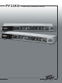
PV
®
23XO
2-Way Stereo/3-Way Mono Crossover
For more information on other great Peavey products, visit your local Peavey dealer or go online to www.peavey.com
Page is loading ...

3
IMPORTANT SAFETY INSTRUCTIONS
WARNING: When using electrical products, basic cautions should always be followed, including the following:
1. Read these instructions.
2. Keep these instructions.
3. Heed all warnings.
4. Follow all instructions.
5. Do not use this apparatus near water.
6. Clean only with a dry cloth.
7. Do not block any of the ventilation openings. Install in accordance with manufacturer’s instructions.
8. Do not install near any heat sources such as radiators, heat registers, stoves or other apparatus (including amplifiers)
that produce heat.
9. Do not defeat the safety purpose of the polarized or grounding-type plug. A polarized plug has two blades with one
wider than the other. A grounding type plug has two blades and a third grounding plug. The wide blade or third prong is
provided for your safety. If the provided plug does not fit into your outlet, consult an electrician for replacement of the
obsolete outlet.
10. Protect the power cord from being walked on or pinched, particularly at plugs, convenience receptacles, and the point
they exit from the apparatus.
11. Note for UK only: If the colors of the wires in the mains lead of this unit do not correspond with the terminals in your
plug‚ proceed as follows:
a) The wire that is colored green and yellow must be connected to the terminal that is marked by the letter E‚ the earth
symbol‚ colored green or colored green and yellow.
b) The wire that is colored blue must be connected to the terminal that is marked with the letter N or the color black.
c) The wire that is colored brown must be connected to the terminal that is marked with the letter L or the color red.
12. Only use attachments/accessories provided by the manufacturer.
13. Use only with a cart, stand, tripod, bracket, or table specified by the manufacturer, or sold with the apparatus. When a
cart is used, use caution when moving the cart/apparatus combination to avoid injury from tip-over.
14. Unplug this apparatus during lightning storms or when unused for long periods of time.
15. Refer all servicing to qualified service personnel. Servicing is required when the apparatus has been damaged in any
way, such as power-supply cord or plug is damaged, liquid has been spilled or objects have fallen into the apparatus,
the apparatus has been exposed to rain or moisture, does not operate normally, or has been dropped.
16. Never break off the ground pin. Write for our free booklet “Shock Hazard and Grounding.” Connect only to a power
supply of the type marked on the unit adjacent to the power supply cord.
17. If this product is to be mounted in an equipment rack, rear support should be provided.
18. Exposure to extremely high noise levels may cause a permanent hearing loss. Individuals vary considerably in suscep
-
tibility to noise-induced hearing loss, but nearly everyone will lose some hearing if exposed to sufficiently intense noise
for a sufficient time. The U.S. Government’s Occupational Safety and Health Administration (OSHA) has specified the
following permissible noise level exposures:
Duration Per Day In Hours Sound Level dBA, Slow Response
8 90
6 92
4 95
3 97
2 100
1 1⁄2 102
1 105
1⁄2 110
1⁄4 or less 115
According to OSHA, any exposure in excess of the above permissible limits could result in some hearing loss. Ear plugs or protectors to
the ear canals or over the ears must be worn when operating this amplification system in order to prevent a permanent hearing loss, if
exposure is in excess of the limits as set forth above. To ensure against potentially dangerous exposure to high sound pressure levels, it is
recommended that all persons exposed to equipment capable of producing high sound pressure levels such as this amplification system be
protected by hearing protectors while this unit is in operation.
SAVE THESE INSTRUCTIONS!
Page is loading ...
Page is loading ...
Page is loading ...

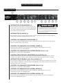
7
PV
®
23XO 2-Way Stereo/3-Way Mono Crossover
Description
Thank you for purchasing a Peavey Electronics PV 23XO 2-Way Stereo/3-Way Mono Crossover. The PV 23XO is a two dual-
channel crossover incorporating Peavey’s legendary low-noise, low-distortion design. Ruggedly constructed, PV 23XO gives the
operator the flexibility to establish a two-way stereo system or run in a three-way mono configuration. The PV 23XO has variable-
state filter controls with 24 dB per octave filters and utilizes XLR inputs and outputs for balanced operation from 20 Hz to 20 kHz.
Features
➡ 2-way stereo/3-way mono operation
➡ Variable-state filter controls
➡ 24 dB/octave filters
➡ XLR inputs and outputs for balanced operation
➡ 20 Hz to 20 kHz operation
ENGLISH

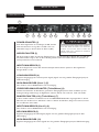
8
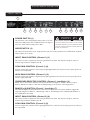
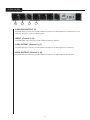
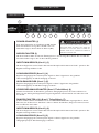
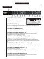
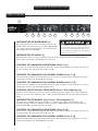
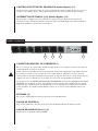
POWER SWITCH (1)
This 2-position rocker switch applies mains power to the unit
when in the ON position. The red LED located to the right of
the Power switch indicates that power is ON.
MODE SWITCH (2)
This switch selects between stereo 2-way operation and mono 3-way operation. The red LED above the Mode
switch indicates mono mode.
INPUT GAIN CONTROL (Channel 1) (3)
This control is used to optimize the channel 1 gain between the mixer and the power amps for channel 1.
Control range is between 0 dB and +12 dB.
LOW GAIN CONTROL (Channel 1) (4)
Controls output level of channel 1 low frequency signal (signal below the selected crossover point) present at
channel 1 low output XLR.
HIGH GAIN CONTROL (Channel 1) (5)
Controls output level of channel 1 high frequency signal (signal above the selected crossover point) present at
channel 1 high output XLR.
CROSSOVER SELECTOR CONTROL (Channel 1 Lows/Highs) (6)
Allows user to choose their desired crossover point for lows and highs for channel 1. Control range is
between 100 Hz and 1 kHz or 1 kHz and 10 kHz depending on the position of the Range Switch.
RANGE (x10) SWITCH (Channel 1 lows/highs) (7)
This switch multiplies the value indicated on the Crossover Selector Control times 10. When engaged, the
range will change from 100 Hz to 1 kHz through 1 kHz to 10 kHz. Range x10 is indicated by illumination of
the red LED above the switch.
INPUT GAIN CONTROL (Channel 2) (8)
This control is used to optimize the channel 2 gain between the mixer and the power amps for channel 2.
Control range is between 0 dB and +12 dB.
LOW GAIN CONTROL (Channel 2) (9)
Controls output level of channel 2 lows signal (signal below the selected crossover point) present at channel 2
low output XLR.
F R O N T PA N E L
S T E R E O M O D E O P E R AT I O N
1
2
4
5
6
7
8
9
12
3
10
11
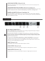
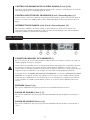
WARNING
THE ON/OFF SWITCH IN THIS APPARATUS
DOES NOT BREAK BOTH SIDES OF THE MAINS.
HAZARDOUS ENERGY MAY BE
PRESENT INSIDE
THE ENCLOSURE WHEN THE POWER SWITCH IS
IN THE OFF POSITION.

9
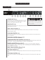
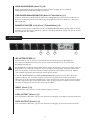
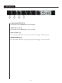
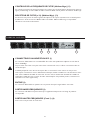
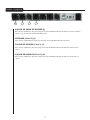
R E A R PA N E L
IEC MAINS CONNECTOR (1)
This is a standard IEC power connector. An AC mains cord having the appropriate AC plug and ratings for
the intended operating voltage is included in the carton.
Never break off the ground pin on any equipment. It is provided for your safety. If the outlet used does
not have a ground pin, a suitable grounding adapter should be used and the third wire should be grounded
properly. To prevent the risk of shock or fire hazard, always make sure that the equalizer and all associated
equipment is properly grounded.
Incorporated into this IEC MAINS CONNECTOR is the MAINS FUSE HOLDER. If for any reason you
are unable to power up this unit, remove the fuse by pulling out the holder. Check to see if the fuse is
operational. If not, then replace with a fuse of the appropriate value and rating. If the fuse continues to fail
contact your nearest Certified Peavey Service Center.
INPUT (Channel 1) (2)
This XLR female 3-pin connector provides a balanced input for channel 1.
LOW OUTPUT (Channel 1) (3)
This XLR male 3-pin connector provides a balanced output for the low frequencies for channel 1.
HIGH OUTPUT (Channel 1) (4)
This XLR male 3-pin connector provides a balanced output for the high frequencies for channel 1.
HIGH GAIN CONTROL (Channel 2) (10)
This controls output level of channel 2 highs signal (signal above the selected crossover point) present at
channel 2 high output XLR.
CROSSOVER SELECTOR CONTROL (Channel 2 lows/highs) (11)
This allows users to choose their desired crossover point for lows and highs for channel 2. The control range
is between 100 Hz and 1 kHz or 1 kHz and 10 kHz, depending on the position of the Range switch.
RANGE (x10) SWITCH (Channel 2 lows/highs) (12)
This switch multiplies the value indicated on the Crossover Selector Control times 10. When engaged, the
range will change from 100 Hz to 1 kHz through 1 kHz to 10 kHz. Range x10 is indicated by the illumination
of the red LED above the switch.
1
2
3
4

10
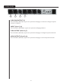
R E A R PA N E L
LOW SUM OUTPUT (5)
This XLR male 3-pin connector provides a balanced output for the low frequencies for both channel 1 and
channel 2, which been summed (added) together.
INPUT (Channel 2) (6)
This XLR female 3-pin connector provides a balanced input for channel 2.
LOW OUTPUT (Channel 2) (7)
This XLR male 3-pin connector provides a balanced output for the low frequencies for channel 2.
HIGH OUTPUT (Channel 2) (8)
This XLR male 3-pin connector provides a balanced output for the high frequencies for channel 2.
7
6
5
8

11
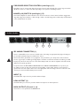
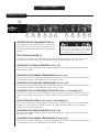
POWER SWITCH (1)
This 2-position rocker switch applies mains power to the unit
when in the ON position. The red LED located to the right of
the Power switch indicates that Power is ON.
MODE SWITCH (2)
This switch selects between stereo 2-way operation and mono 3-way operation. The red LED above the Mode
switch indicates mono mode.
INPUT GAIN CONTROL (3)
This control is used to optimize the gain between the mixer and the power amps. The control range is
between 0 dB and +12 dB.
LOW GAIN CONTROL (4)
This controls the output level of low frequency signals (those below the selected crossover point) present at
the low output XLR.
HIGH GAIN CONTROL (Channel 1) (5)
This function is non-operational in MONO Mode.
CROSSOVER SELECTOR CONTROL (lows/mids) (6)
This allows the user to choose their desired crossover point for lows and mids. Control range is between 100
Hz and 1 kHz or 1 kHz and 10 kHz depending on the position of the Range Switch.
RANGE (x10) SWITCH (lows/mids) (7)
This switch multiplies the value indicated on the Crossover Selector Control times 10. When engaged, the
range will change from 100 Hz to 1 kHz through 1 kHz to 10 kHz. Range x10 is indicated by the illumination
of the red LED above the switch.
INPUT GAIN CONTROL (Channel 2) (8)
This function is non operational in MONO Mode.
MID GAIN CONTROL (9)
This controls the output level of mid signals (those below the selected crossover point) present at mid output
XLR.
HIGH GAIN CONTROL (10)
This controls the output level of the highs (signals above the selected crossover point) present at high output
XLR.
F R O N T PA N E L
M O N O M O D E O P E R AT I O N
1
2
4
5
6
7
8
9
12
3
10
11
WARNING
THE ON/OFF SWITCH IN THIS APPARATUS
DOES NOT BREAK BOTH SIDES OF THE MAINS.
HAZARDOUS ENERGY MAY BE
PRESENT INSIDE
THE ENCLOSURE WHEN THE POWER SWITCH IS
IN THE OFF POSITION.

12
R E A R PA N E L
IEC MAINS CONNECTOR (1)
This is a standard IEC power connector. An AC mains cord having the appropriate AC plug and ratings for
the intended operating voltage is included in the carton.
Never break off the ground pin on any equipment. It is provided for your safety. If the outlet used does
not have a ground pin, a suitable grounding adapter should be used and the third wire should be grounded
properly. To prevent the risk of shock or fire hazard, always make sure that the equalizer and all associated
equipment is properly grounded.
Incorporated into this IEC MAINS CONNECTOR is the MAINS FUSE HOLDER. If for any reason you
are unable to power up this unit, remove the fuse by pulling out the holder. Check to see if the fuse is
operational. If not, then replace with a fuse of the appropriate value and rating. If the fuse continues to fail
contact your nearest Certified Peavey Service Center.
INPUT (2)
This XLR female 3-pin connector provides a balanced input.
LOW OUTPUT (3)
This XLR male 3-pin connector provides a balanced output for the low frequencies.
HIGH OUTPUT (Channel 1) (4)
This function is non-operational in MONO Mode.
CROSSOVER SELECTOR CONTROL (mids/highs) (11)
This allows users to choose their desired crossover point for mids and highs. The control range is between
100 Hz and 1 kHz or 1 kHz and 10 kHz, depending on the position of the Range switch.
RANGE (x10) SWITCH (mids/highs) (12)
This switch multiplies the value indicated on the Crossover Selector Control times 10. When engaged, the
range will change from 100 Hz to 1 kHz through 1 kHz to 10 kHz. Range x10 is indicated by the illumination
of the red LED above the switch.
1
2
3
4

13
R E A R PA N E L
LOW SUM OUTPUT (5)
This function is non-operational in MONO Mode.
INPUT (Channel 2) (6)
This function is non-operational in MONO Mode.
MID OUTPUT (7)
This XLR male 3-pin connector provides a balanced output for the mid frequencies.
HIGH OUTPUT (8)
This XLR male 3-pin connector provides a balanced output for the high frequencies.
7
6
5
8

14
14
PV
®
23XO
2-Way Stereo/3-Way Mono
SPECIFICATIONS
CONTROLS AND SWITCHES
Channel Gain Control:
0 to +12 dB
Low Frequency Level Control: -∞ to +6 dB
High Frequency Level Control: -∞ to +6 dB
Low Frequency to High Frequency crossover: 100 Hz to 1 Khz x10 range: Changes Low Frequency
to Mid Frequency from (100 Hz to 1 kHz) to
(1kHz to 10 kHz)
2-way stereo/3-way mono changes the unit from
2-way stereo or 3-way mono
FREQUENCY RESPONSE
Each output is -3 dB at the selected crossover frequency value. Outputs are essentially flat within their
relative passbands.
Distortion: Less than 0.02% THD @ +4 dBu,@ 1 kHz
Hum and Noise: Crossover controls set @ 1 kHz, all level controls set at 0 dB; 22 Hz to 22 kHz, unweighted gain @
0dB(ref +4dBu) - 90dB
Low Frequency Output: -86 dBu below 80 dB
High Frequency Output: -84 dBu below -78 dB
Maximum Input Level: +14 dBu, (channel gain @ 0 dB input level controls set at 0 dB) +22 dBu
Maximum Output Level: +22 dBu, unbalanced +28 dBu, balanced
Input Impedance: 10 k ohms unbalanced
CONNECTORS
Inputs: XLR Balanced
Outputs: XLR Balanced
Power Requirements: 120V AC, 50/60 Hz, 20 watts (domestic model)
Page is loading ...
Page is loading ...
Page is loading ...
Page is loading ...
Page is loading ...
Page is loading ...
Page is loading ...
Page is loading ...
Page is loading ...
Page is loading ...
Page is loading ...
Page is loading ...
Page is loading ...
Page is loading ...
Page is loading ...
Page is loading ...
Page is loading ...
Page is loading ...
Page is loading ...
Page is loading ...
Page is loading ...
Page is loading ...
Page is loading ...
Page is loading ...

39
PEAVEY ELECTRONICS CORPORATION LIMITED WARRANTY
Effective Date: July 1, 1998
What This Warranty Covers
Your Peavey Warranty covers defects in material and workmanship in Peavey products purchased and serviced in the U.S.A. and Canada.
What This Warranty Does Not Cover
The Warranty does not cover: (1) damage caused by accident, misuse, abuse, improper installation or operation, rental, product modification or neglect; (2) dam
-
age occurring during shipment; (3) damage caused by repair or service performed by persons not authorized by Peavey; (4) products on which the serial number
has been altered, defaced or removed; (5) products not purchased from an Authorized Peavey Dealer.
Who This Warranty Protects
This Warranty protects only the original retail purchaser of the product.
How Long This Warranty Lasts
The Warranty begins on the date of purchase by the original retail purchaser. The duration of the Warranty is as follows:
Product Category Duration
Guitars/Basses, Amplifiers, Pre-Amplifiers, Mixers, Electronic
Crossovers and Equalizers 2 years *(+ 3 years)
Drums 2 years *(+ 1 year)
Enclosures 3 years *(+ 2 years)
Digital Effect Devices and Keyboard and MIDI Controllers 1 year *(+ 1 year)
Microphones 2 years
Speaker Components (incl. speakers, baskets, drivers,
diaphragm replacement kits and passive crossovers)
and all Accessories 1 year
Tubes and Meters 90 days
[*Denotes additional warranty period applicable if optional Warranty Registration Card is completed and returned to Peavey by original retail purchaser within 90 days of purchase.]
What Peavey Will Do
We will repair or replace (at Peavey's discretion) products covered by warranty at no charge for labor or materials. If the product or component must be shipped to
Peavey for warranty service, the consumer must pay initial shipping charges. If the repairs are covered by warranty, Peavey will pay the return shipping charges.
How To Get Warranty Service
(1) Take the defective item and your sales receipt or other proof of date of purchase to your Authorized Peavey Dealer or Authorized Peavey Service Center.
OR
(2) Ship the defective item, prepaid, to Peavey Electronics Corporation, International Service Center, 412 Highway 11 & 80 East, Meridian, MS 39301 or Peavey
Canada Ltd., 95 Shields Court, Markham, Ontario, Canada L3R 9T5. Include a detailed description of the problem, together with a copy of your sales receipt or
other proof of date of purchase as evidence of warranty coverage. Also provide a complete return address.
Limitation of Implied Warranties
ANY IMPLIED WARRANTIES, INCLUDING WARRANTIES OF MERCHANTABILITY AND FITNESS FOR A PARTICULAR PURPOSE, ARE LIMITED IN DURATION TO THE
LENGTH OF THIS WARRANTY.
Some states do not allow limitations on how long an implied warranty lasts, so the above limitation may not apply to you.
Exclusions of Damages
PEAVEY'S LIABILITY FOR ANY DEFECTIVE PRODUCT IS LIMITED TO THE REPAIR OR REPLACEMENT OF THE PRODUCT, AT PEAVEY'S OPTION. IF WE ELECT TO
REPLACE THE PRODUCT, THE REPLACEMENT MAY BE A RECONDITIONED UNIT. PEAVEY SHALL NOT BE LIABLE FOR DAMAGES BASED ON INCONVENIENCE, LOSS OF
USE, LOST PROFITS, LOST SAVINGS, DAMAGE TO ANY OTHER EQUIPMENT OR OTHER ITEMS AT THE SITE OF USE, OR ANY OTHER DAMAGES WHETHER INCIDENTAL,
CONSEQUENTIAL OR OTHERWISE, EVEN IF PEAVEY HAS BEEN ADVISED OF THE POSSIBILITY OF SUCH DAMAGES.
Some states do not allow the exclusion or limitation of incidental or consequential damages, so the above limitation or exclusion may not apply to you.
This Warranty gives you specific legal rights, and you may also have other rights which vary from state to state.
If you have any questions about this warranty or service received or if you need assistance in locating an Authorized Service Center, please contact the Peavey
International Service Center at (601) 483-5365 / Peavey Canada Ltd. at (905) 475-2578.
Features and specifications subject to change without notice.

Features and specifications subject to change without notice.
Peavey Electronics Corporation • 711 A Street • Meridian • MS • 39301
(601) 483-5365 • FAX (601) 486-1278 • www.peavey.com
EX000008
©2004
-
 1
1
-
 2
2
-
 3
3
-
 4
4
-
 5
5
-
 6
6
-
 7
7
-
 8
8
-
 9
9
-
 10
10
-
 11
11
-
 12
12
-
 13
13
-
 14
14
-
 15
15
-
 16
16
-
 17
17
-
 18
18
-
 19
19
-
 20
20
-
 21
21
-
 22
22
-
 23
23
-
 24
24
-
 25
25
-
 26
26
-
 27
27
-
 28
28
-
 29
29
-
 30
30
-
 31
31
-
 32
32
-
 33
33
-
 34
34
-
 35
35
-
 36
36
-
 37
37
-
 38
38
-
 39
39
-
 40
40


Peavey 23XO User manual
- Category
- Supplementary music equipment
- Type
- User manual
- This manual is also suitable for
Ask a question and I''ll find the answer in the document
Finding information in a document is now easier with AI
in other languages
- français: Peavey 23XO Manuel utilisateur
- español: Peavey 23XO Manual de usuario
- Deutsch: Peavey 23XO Benutzerhandbuch
Related papers
-
Peavey XR8300 Owner's manual
-
-
Peavey PV 20 User manual
-
-
-
-
-
 Peavy PV Series Power Amplifer Owner's manual
-
-
Peavey CS 4000 Owner's manual

Other documents
-
Crest Audio CC 4000 User manual
-
Crest Audio CPX 3800 User manual
-
Crest Audio Pro-LITE 2.0 DSP User manual
-
-
 Architectural Acoustics IP-Six User manual
-
Crest Audio Pro-LITE 7.5 User manual
-
-
Omnitronic XO-23 Active crossover User manual
-
JBSYSTEMS LIGHT EC 102-X0210 Owner's manual
-
JBSYSTEMS LIGHT EC 102 Owner's manual
