
Installation
Instructions
Instructions
d’installation
36″ Stainless Steel
Gas Cooktops
Natural Gas Model:
ZGU385N
LP Gas Model:
ZGU385L
Questions?
Call 800.GE.CARES
or Visit our Website at:
www.monogram.com
Appelez le Centre de réponse 1.800.561.3344
ou visitez notre site Web à l’adresse :
www.electromenagersge.ca
31-10634-2
08-07 JR
Surfaces de cuisson
au gaz de acier
inoxydable de 36 po
(91 cm)
Modèle à gaz naturel :
ZGU385N
Modèle à gaz PL :
ZGU385L
La section française commence
à la page 19.

BEFORE YOU BEGIN
Read these instructions completely and carefully.
•
IMPORTANT — Save these instructions
for local inspector’s use.
•
IMPORTANT — Observe all governing
codes and ordinances.
• Note to Installer – Be sure to leave these
instructions with the Consumer.
• Note to Consumer – Keep these instructions for
future reference.
• Product failure due to improper installation is not
covered under the Warranty.
WARNING — This appliance must be
properly grounded.
•
IMPORTANT — Leak testing of the
appliance shall be conducted according to the
manufacturer’s instructions.
• Proper installation is the responsibility of the
installer and product failure due to improper
installation is NOT covered under warranty.
FOR YOUR SAFETY:
WARNING — If the information
in this manual is not followed exactly, a fire,
explosion or gas leak may result, causing
property damage, personal injury or death.
Do not store or use gasoline or other
flammable vapors and liquids in the
vicinity of this or any other appliance!
WHAT TO DO IF YOU
SMELL GAS:
• Do not try to light any appliance. Do not touch
any electrical switch; do not use any phone in
your building.
• Immediately call your gas supplier from a
neighbor’s phone. Follow the gas supplier’s
instructions.
• If you cannot reach your gas supplier, call the fire
department.
Installation and service must be performed by
a qualified installer, service agency or the gas
supplier.
WARNING — Disconnect all electrical
power at the main circuit breaker or fuse box
before installing.
This cooktop has been design certified by Underwriters
Laboratories. You’ll find safety precautions in your
Owner’s Manual. Read them carefully.
• Installation of this cooktop must conform with
local codes or, in the absence of local codes, with
the National Fuel Gas Code, ANSI Z223.1/NFPA
54–Latest Edition.
• Be sure your cooktop is installed properly by a
qualified installer or service technician.
• To eliminate reaching over surface burners,
cabinet storage above burner should be avoided.
• Do not install the unit near an outside door or
where a draft may affect its use.
IN THE COMMONWEALTH OF MASSACHUSETTS:
• This product must be installed by a licensed
plumber or gas fitter.
• When using ball-type gas shut-off valves,
they shall be the T-handle type.
• A flexible gas connector, when used, must not
exceed 3 feet.
Be sure the installation of this product in a mobile
home conforms with the Manufactured Home
Construction and Safety Standard, Title 24 CFR,
Part 3280. If this standard does not apply, you
must follow the standard for Manufactured Home
Installations, ANSI A225.1 and Manufactured Home
Installations, Sites and Communities, ANSI/NFPA
501A or with local codes. You can get a copy of
the Federal Standard by Writing:
Office of Mobile Home Standards
HUD Building
451 7th Street, S.W.
Washington, D.C. 24010
Safety Information
2

CONTENTS
Installation Preparation
Models Available . . . . . . . . . . . . . . . . . . . . . . . . .4
Parts Included . . . . . . . . . . . . . . . . . . . . . . . . . . . 4
Materials You May Need . . . . . . . . . . . . . . . . . 4
Tools You Will Need . . . . . . . . . . . . . . . . . . . . . . 4
Advance Planning and
Installation Options . . . . . . . . . . . . . . . . . . . . . . 5
Pre-Installation Checklist . . . . . . . . . . . . . . . . . 6
Dimensions and Clearances . . . . . . . . . . . . . . 7
Gas Supply Locations . . . . . . . . . . . . . . . . . . . . 8
Installation Instructions
Step-by-Step Instructions . . . . . . . . . . . . 9–11
Operation Checklist . . . . . . . . . . . . . . . . . . . . . 11
Installation Options
Installation With a Downdraft Vent . . . . . . 12
Installation Over a Warming Drawer . . . . 13
Installation Over a Single Oven . . . . . . . . . . 14
Installation Instructions for Natural
to LP Gas Conversion
Tools You Will Need . . . . . . . . . . . . . . . . . . . . 15
Adjusting the Regulator . . . . . . . . . . . . . . . . . 15
Changing the Orifices . . . . . . . . . . . . . . . 15, 16
Adjusting Burner Flames . . . . . . . . . . . . . . . . 16
Installation Instructions for LP
to Natural Gas Conversion
Tools You Will Need . . . . . . . . . . . . . . . . . . . . 17
Adjusting the Regulator . . . . . . . . . . . . . . . . . 17
Changing the Orifices . . . . . . . . . . . . . . . 17, 18
Adjusting Burner Flames . . . . . . . . . . . . . . . . 18
ELECTRICAL REQUIREMENTS
This appliance must be supplied with the proper
voltage and frequency and connected to an
individual, properly grounded branch circuit, protected
by a circuit breaker or fuse having amperage as noted
on the rating plate.
We recommend you have the electrical wiring and
hookup of your cooktop connected by a qualified
electrician. After installation, have the electrician show
you where your main cooktop disconnect is located.
Check with your local utilities for electrical codes
which apply in your area. Failure to wire your
cooktop according to governing codes could
result in a hazardous condition. If there are no codes,
your cooktop must be wired and fused to meet the
requirements of the National Electrical Code,
ANSI/NFPA No. 70—Latest Edition. You can
get a copy by writing:
National Fire Protection Association
Batterymarch Park
Quincy, MA 02269
In Canada, your cooktop must be wired and
fused to meet the requirements of the Canadian
Electrical Code.
Safety Information
3

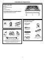
PARTS INCLUDED TOOLS YOU WILL NEED
FOR INSTALLATION
MODELS AVAILABLE
ZGU385N
36″ natural gas cooktop
ZGU385L
36″ LP gas cooktop
These models are factory set for either natural gas
or LP gas operation. Be sure to order the correct
model for the installation situation.
Saber Saw
Pencil
Safety Glasses
1/8″ Drill Bit &
Electric or Hand
Drill
Ruler or
Straightedge
Phillips Head
Screwdriver
Pipe Wrench
MATERIALS YOU MAY NEED
2 Hold
Down Brackets
Shut Off
Valve
Pipe Fittings
CSA-Approved Flexible Gas Line
1/2
″ Min. ID, 1/2″ NPT Connection,
3-foot Maximum Length (Massachusetts Only)
NOTE: Purchase new line, do not use
previously used flexible gas line.
Joint
Sealant
Regulator
2 Screws
Installation Preparation
4

ADVANCE PLANNING
• Refer to “Installation Preparation” for
information on appropriate placement and
necessary clearances when planning
installation.
• Avoid placing cabinetry directly above cooktop
when possible.
• If cabinetry is used above cooking surface:
– Use cabinets no more than 13″ deep.
– Maintain 30″ minimum clearance between
cooktop and unprotected cabinets directly
above cooktop.
– If clearance is less than 30″, protect cabinet
bottoms with flame-retardant millboard at
least 1/4″ thick, or gypsum board at least
3/16″ thick, covered with 28 gauge sheet
steel or .02″ thick copper.
– Clearance between cooktop and protected
cabinetry must not be less than 24″.
– An exhaust hood that projects at least 5″
beyond front of cabinets can reduce risk
of burns caused by reaching over heated
surface units.
– Working areas adjacent to the cooktop
should have 18″ minimum clearance between
countertop and cabinet bottom.
•A 36″ or wider exhaust hood with 350 CFM or
greater airflow rating is recommended for use
over this Monogram cooktop.
• Installation must conform with local codes.
In the absence of local codes, the gas cooktop
must comply with the National Fuel Gas Code,
ANSI Z223.1, latest edition.
• Gas supply should be located near the opening
for this cooktop (see Preparing the Opening and
Gas Connection sections of this manual). The
supply should provide natural gas at 7″ of water
column pressure (11″ of water column for LP
gas) and a maximum of 14″ of water column
for natural or LP gas.
• The electric spark ignition feature for this
model requires a 120V electrical power supply
be located in the immediate vicinity of this
cooktop (see Electrical Connections section
of this manual).
WB28T10185 High Altitude Kit
For operation above 5,000 feet, order
WB28T10185 Conversion Kit. This kit includes
orifices for both LP and Natural gas operation.
Installation Preparation
5
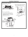
INSTALLATION OPTIONS
Cooktop and ZVB36 Downdraft Vent Combination
Installation
These cooktops may be installed with a 36″
Monogram Downdraft Vent, model ZVB36.
See page 12 for cutout and clearances.
– The countertop must have a deep flat surface to
accommodate the combined installation of the
cooktop and vent.
– The downdraft vent with blower, motor and
ductwork will occupy the base cabinet.
– Consideration must be given to electrical and gas
supply locations. See page 8.
Cooktop and ZTD910 or ZKD910 Warming Drawer
Combination Installation
These cooktops may be installed over a Monogram
30″ or 27″ Warming Drawer, model ZTD910 or
ZKD910. See page 13 for cutout and clearances.
– Consideration must be given to electrical and gas
supply locations. See page 8.
Cooktop and ZET1 or ZET938 Single Oven
Combination Installation
These cooktops may be installed over a Monogram
30″ Oven, model ZET1 or ZET938. See page 14 for
cutout and clearances.
– Consideration must be given to electrical and gas
supply locations. See page 8.
Installation Above Cabinet Drawers
• When installing the cooktop above a base
cabinet with drawers, it may be necessary to
use a shorter depth (front to back) drawer to
allow clearance for the gas connection.

PRE-INSTALLATION CHECKLIST
1. When preparing cooktop opening, make sure
the inside of the cabinet and the cooktop do
not interfere with each other. (See section on
preparing the opening.)
2. Slide the cooktop out of the end of the box.
Remove packaging materials, grate boxes,
regulator and literature package from the
cooktop before beginning installation.
• Use the shipping carton as a pad to protect
customer countertops or flooring.
3. Remove Installation Instructions from literature
package and read them carefully before you
begin.
Be sure to place all literature, Owner’s Manual,
Installations, etc. in a safe place for future
reference.
4. Make sure you have all the tools and materials
you need before starting the installation of the
cooktop.
5. Your home must provide the adequate electrical
service needed to safely and properly use your
cooktop. (Refer to section on electrical
requirements.)
6. When installing your cooktop in your home, make
sure all local codes and ordinances are followed
exactly as stated.
7. Make sure the wall coverings, countertop and
cabinets around the cooktop can withstand heat
(up to 200°F) generated by the cooktop.
Foam support
Left and right side
grate boxes
Installation Preparation
6
Center
grate box
Foam
packaging
Regulator
taped to the
underside

DIMENSIONS AND CLEARANCES
1. Overall cooktop dimensions:
2. Use a 36″ or wider base cabinet.
• Cut the opening in the countertop. To ensure
accuracy, it is best to make a template for the
opening. Make sure the sides of the opening are
parallel and the rear and front cuts are exactly
perpendicular to the sides.
• Observe all minimum clearances.
3. Make sure the wall coverings, countertop and
cabinets around the cooktop can withstand heat
(up to 200°F) generated by the cooktop.
3-3/4″
36-3/4″
21-3/16″
deep at
center
12″ min.
from cutout
to side wall
2-1/2″ min.
from cutout
to front of
countertop
3-3/8″ min.
from cutout
to rear vertical
combustibles
12″ min.
from cutout
to side wall
Installation Preparation
7
33-7/8″
36″ or wider
cabinet base
recommended
19-1/8″
30″ min.
13″ max.
36″
min.
18″ min.
20-5/16″

POWER SUPPLY LOCATIONS
Gas supply:
These cooktops are shipped from the factory set
for either natural gas or LP gas. Check to be sure
you have the correct cooktop for the type of gas
being used.
• The pressure regulator must be connected in series
with the manifold of the cooktop and must remain
in series with the supply line regardless of type of
gas being used.
• The natural gas model is designed to operate at
5″ water column pressure. A regulator is required
at the natural gas source to provide a minimum
of 6″ water column to the cooktop regulator.
• The liquid propane model is designed to operate at
10″ water column pressure. A regulator is required
at the LP source to provide a minimum of 11″ water
column to the cooktop regulator.
• Maximum inlet pressure for the regulator supplied
with the cooktop is 14″ water column regardless of
the gas being used.
For ease of installation, and if local codes permit,
the gas supply line into the cooktop should be 1/2″
or 3/4″ ID flexible metal appliance connector, three
to five feet long.
NOTE: Purchase new flexible line. DO NOT USE OLD,
PREVIOUSLY USED FLEXIBLE LINE.
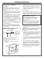
Rear–Burner Box
The gas inlet is
located on the
bottom of the
burner box at
the rear and
center.
• Make gas connection through rear wall, or on
cabinet floor at rear, as illustrated.
1. Install the house gas supply at least 1″ from
the back wall.
2. Locate the electrical outlet 12″ below the
countertop.
Install a manual shut-off valve in the gas line in an
easily accessible location outside the cooktop. Be
sure you know how and where to shut off the gas
supply to the cooktop. Install the electrical outlet
12″ below the countertop.
Electrical supply:
This cooktop features pilotless electric ignition for
energy savings and reliability. It operates on a 120 volt,
60 Hz power supply. A separate circuit, protected by a
15 amp time delay fuse or circuit breaker, is required.
• A properly-grounded 3-prong receptacle should
be located within reach of the cooktop’s four-foot
power cord.
IMPORTANT: (Please read carefully). FOR PERSONAL
SAFETY, THIS APPLIANCE MUST BE PROPERLY
GROUNDED.
• The power cord of this appliance is equipped with
a three-prong (grounding) plug which mates with a
standard three-prong grounding wall receptacle to
minimize the possibility of electric shock hazard
from this appliance.
• The customer should have the wall receptacle and
circuit checked by a qualified electrician to make sure
the receptacle is properly grounded and has correct
polarity.
• Where a standard two-prong wall receptacle is
encountered, it is the personal responsibility and
obligation of the customer to have it replaced with
a properly grounded three-prong wall receptacle.
Do Not, Under Any Circumstances, Cut Or Remove
The Third (Ground) Prong From The Power Cord.
Do not use an extension cord.
Installation Preparation
8
Optional Combination Installations
This cooktop may be installed in combination
with a ZVB36 Monogram Downdraft Vent,
a ZET1 or ZET938 Single Oven or a ZTD910
Warming Drawer.
• The gas and electrical supply must be located
where it will not interfere with vent housing, the
oven or the warming drawer. Review pages 12
to 14 for additional installation requirements.
1”
min.
12”
Gas
supply
line
1-15/16”
16-15/16”
Gas Inlet

Installation Instructions
9
INSTALL THE COOKTOP
A. Remove the screws on the sides of the cooktop
burner box. Use those screws to attach the side
mounting brackets.
B. Insert the cooktop centered into the cutout
opening. Make sure the front edge of the
countertop is parallel to the cooktop.
Check clearances at the front, back and sides.
Secure the hold-down bracket to the cabinet
sides with screws.
1
Cooktop
INSTALL PRESSURE REGULATOR
WARNING: Never reuse old flexible
connectors. The use of old flexible connectors can
cause gas leaks and personal injury. Always use
new flexible connectors when installing a gas
appliance.
To reduce the possibility of gas leaks, apply teflon
tape or a thread compound approved for use with
LP or Natural gases to all threaded connections.
A. Screw the regulator onto the burner box
bottom pipe connection. Make sure the top of
the regulator is facing toward the cabinet front,
and the arrow on the back of the regulator
points to the cooktop.
2
Pressure
regulator
Shut-off
valve
Electrical outlet 12″
below countertop
To cooktop
Rear view
of
regulator
(note
direction
of arrow)
CONNECT ELECTRICAL
• Check to be sure the receptacle is properly
grounded.
• Plug in the power cord.
3
INSTALL PRESSURE REGULATOR
(cont.)
OPTION: You can install a 90º elbow (not supplied)
onto the gas inlet and route the gas connections to
avoid interference when installed over an oven,
with a downdraft vent, a warming drawer or other
cabinetry features.
B. Complete the connection between the regulator
and the shut-off valve.
C. Before testing for leaks, make sure all burner
knobs are in the OFF position.
After connecting the cooktop to gas, check
system for leaks with a manometer. If a manometer
is not available, turn the gas supply on to the
cooktop and use a liquid leak detector at all
joints and connections to check for leaks.
Tighten all connections if necessary to prevent gas
leakage in the cooktop or supply line.
WARNING: Do not use a flame to
check for leaks.
Disconnect the cooktop and its individual shut-off
valve from the gas supply piping system during any
pressure testing of that system at test pressures
greater than 1/2 psig (3.5 kPa).
Isolate the cooktop from the gas supply piping
system by closing its individual shut-off valve during
any pressure testing of the gas supply system at
test pressures equal to or less than 1/2 psig (3.5 kPa
).
2
Burner Box
90
º
Elbow

ASSEMBLE BURNERS,
CHECK IGNITION
The electrode of the electronic ignition system
is positioned above the surface of the burner
base. Do not remove a burner cap or touch the
electrode of a burner while another is turned
on. Damage or electrical shock may occur.
A.Remove tape holding burners in position. Note
the position of one larger burner base, head and
cap. The large and regular size pieces are not
interchangeable.
B. Place burner heads over the burner base.
Make sure the hole in the burner head is properly
aligned with the electrode in the burner base.
C. Place the burner caps on the burner heads.
Make sure that the burner caps are properly
seated on the burner heads.
4
Burner cap not properly seated
Burner cap properly seated
Installation Instructions
10
Burner cap
Burner head
assembly
Burner
base
Electrode
ASSEMBLE BURNERS,
CHECK IGNITION (cont.)
D. Check igniters.
Operation of the electric igniters should
be tested after the cooktop and supply line
have been carefully checked for leaks and the
cooktop has been connected to the electrical
power.
• Push and turn a burner valve to the LITE
position. All spark igniters will make a series
of sparks (ticking sounds), but only the burner
turned to LITE will light.
– The burner should light when gas is available
to the burner.
– Once the burner lights, it should be turned to
another position.
• Test each valve separately until all burners have
been checked.
IMPORTANT: If the igniter electrodes continue to
spark after all of the burners are lit, check that
each burner component is assembled and
properly seated.
E. Burner ignition.
Cooktop Spark Ignition—When you turn the
cooktop knob to LITE, the spark igniter makes
a series of electric sparks (ticking sounds) which
light the burner. During a power failure, the
burners will not light automatically. In an
emergency, a cooktop burner may be lit
with a match by following the steps below.
WARNING: Lighting gas burners with
a match is dangerous. You should match light
the cooktop burners only in an emergency.
• Light a match and hold the flame near the
burner you want to light. Wooden matches
work best.
• Push in and turn the control knob slowly.
Be sure you are turning the correct knob
for the burner you are lighting.
NOTE: If the burner does not light within five
seconds, turn the knob off and wait one minute
before trying again.
4

Installation Instructions
11
ASSEMBLE BURNERS,
CHECK IGNITION (cont.)
F. Turn on each burner. On LP models, flames
should be blue in color but may have yellow
tips. Natural gas models should have soft, blue
flames. The burner flames should not flutter or
blow away from the burner. The flame should be
no less than 1/4″ on the lowest setting and no
greater than 1-1/2″ on highest setting.
WARNING:If you attempt to measure
the flame, please use caution. Burns could result.
G. The three cooktop grates are designed for
specific positions. For maximum stability,
these grates should only be used in their proper
positions: they should not be interchanged.
Position the two side grates with locking rails
toward the center grate so that a continuous
“arc” is formed with the center ribs of all three
grates. Make sure the center grate is locked into
position over the rails on the side grates and
that all the grates are stable and level.
4
Burners should be checked frequently
Cooktop burner
1/4″ to
1-1/2″
“OUTSIDE”
edge
“OUTSIDE”
edge
“INSIDE”
edges
OPERATION CHECKLIST
1. Make sure all controls are left in the OFF
position.
2. The serial plate for your cooktop is located
on the bottom of the burner box. In addition to
the model and serial numbers, it tells you the
ratings of the burners and the type of fuel and
pressure the cooktop was adjusted for when it
left the factory.
3. When ordering parts, always include the serial
number, model number and a code letter to
ensure proper replacement parts.
4. Check again to be sure all installation
procedures have been completed.

COOKTOP INSTALLATION WITH A
36″ MONOGRAM DOWNDRAFT VENT,
MODEL ZVB36
The installation of the downdraft vent with
this cooktop requires careful consideration.
Both the cooktop and the vent must be installed
according to each specific installation instruction.
BASE CABINET REQUIREMENTS
The combined installation will fit in a standard
24″ deep base cabinet. Use a 36″ or wider base
cabinet.
– The vent housing, blower and ductwork will
occupy the base cabinet.
COOKTOP REQUIREMENTS
The countertop must have a deep flat surface to
accommodate the cooktop and vent. Countertops
with a rolled front edge and backsplash will not
provide the flat surface area required.
• Review the illustration to determine the countertop
surface requirements.
– All cutout clearances for this installation must be
observed.
POWER SUPPLY
If local codes permit, the vent and cooktop may
operate from the same 120V, 15 amp duplex outlet.
Locate the gas and electrical supply as shown on
page 8.
21-11/16″
cutout
depth
3/8″
36-3/4″
3/8″
1/8″
gap
3-3/8″ min. cooktop
cutout to rear vertical
combustible surface
23-5/16″
total flat
surface
required at
center
12″ min. cutout to
wall, both sides
2-1/2″ min. clearance
to cutout
Front edge of countertop
7/16″ cooktop overlap
(1-1/4″ at center)
Installation Options
12
34″ cooktop and
vent area cutout

Installation Options
13
COOKTOP INSTALLATION OVER A
MONOGRAM WARMING DRAWER,
MODEL ZTD910 OR ZKD910
These cooktops may be installed over a 30″
or 27″ Warming Drawer. Both the cooktop and
the warming drawer must be installed according to
each specific installation instruction.
Use a 36″ or wider base cabinet.
• Plan gas supply location carefully to avoid
interference with the warming drawer.
POWER SUPPLY:
If local codes permit, the cooktop and warming
drawer may operate from the same 120V duplex
outlet. Refer to installation instructions for details.
Install 2x4 or 2x2 anti-tip block against
rear cabinet wall 9″ from cutout floor
to bottom of block
23-1/2″ min.
Cooktop 33-7/8″
19-1/8″
2-1/2″ min.
1-1/2″ cabinet top
5-1/2″ min.
NOTE: When installing a Monogram Warming Drawer
below a cooktop, a solid barrier must be installed at least
1″ from the lowest point of the bottom of cooktop
burner box to the top of cutout. See Warming Drawer
Installation Instructions for details.
36″
countertop
height
9-1/4″
A
25″
9″
Dim. A
ZTD910 28-1/2″
ZKD910 25-1/2″

COOKTOP INSTALLATION OVER
A 30″ MONOGRAM SINGLE OVEN,
MODEL ZET1 OR ZET938
These cooktops may be installed over the
Monogram ZET1 or ZET938 single oven. Both the
cooktop and the oven must be installed according
to each specific installation instruction.
– Allow 4″ Min. clearance from the top of the
countertop to the top of the oven cutout.
Use a 36″ or wider base cabinet.
• For best appearance, the cooktop should be
centered over the oven.
POWER SUPPLY
The oven requires a separate, properly grounded
20 Amp, 3-wire 208 or 240 volt, 60 Hz power supply.
The cooktop requires a separate 120V power supply.
See page 8. Where codes permit, the gas shut-off
valve may be located in an adjacent cabinet or
other easily accessible location.
Use two 2x4’s or equivalent runners spaced 25″ centerline
to centerline in the opening and flush with top of toekick.
Or elevate the oven floor to desired height. The support must
be level, rigidly mounted and capable of supporting 200 lbs.
23-1/2″ min.
Cooktop
33-7/8″
19-1/8″
2-1/2″ min.
1-1/2″ cabinet top
4″ min.
36″
countertop
height
27-1/4″ min.
27-5/16″ max.
28-1/2″ min.
28-5/8″ max.
25″
C
L
25″
Installation Options
14
C
L

15
ADJUST THE REGULATOR
A. Disconnect all electrical power, at the main circuit
breaker or fuse box.
B. Shut off the gas supply to the cooktop by closing the
manual shut-off valve.
C. Adjust the pressure regulator by the following
instructions:
• Unscrew the cap.
• Place your thumb against the flat side of the spring
retainer and press down to remove the retainer.
• Carefully look at the spring retainer to locate the NAT
or LP position.
• Turn the spring retainer over so that the desired gas is
showing on the bottom.
• Snap the retainer back into position.
• Screw the cap back onto the regulator.
1
CHANGE BURNER ORIFICES
INSTALLATION TIP: First remove all
orifices and then start replacing them.
This will help to prevent the possibility
that some may not be replaced.
A. Remove the burner grates,
burner caps and burner heads.
B. Using a 7mm nut driver, remove the
top burner orifices. There are two
orifices per burner.
The main orifice is
located low in the center
of the burner, while the
simmer orifice is located
higher beside the center
of the burner.
2
DOWN
FOR OFF
NAT
LP
LP
NAT
LP
NAT
NAT
LP
Gasket
Cap
Spring
retainer
L.P./propane
position
NAT.
position
Pressure regulator
Burner cap
Burner
head
Burner
base
Spark igniter
Main
orifice
Simmer
orifice
SAFETY INFORMATION
The pressure regulator and burner orifices are set for
natural gas operation.
To convert this cooktop from natural gas operation to
LP operation, the regulator and burner orifices must be
converted. LP burner orifices are attached to the regulator.
CAUTION — The cooktop, as shipped from the
factory, is set for use with its intended gas. If you wish
to use your cooktop with the alternate gas, you must
first replace the orifices and convert the pressure
regulator.
WARNING — This conversion must be
performed by a qualified installer or gas supplier in
accordance with the manufacturer’s instructions and
all codes and requirements of the authority having
jurisdiction. Failure to follow instructions could result in
serious injury or property damage. The qualified agency
performing this work assumes responsibility for the
conversion.
CAUTION — The following adjustments must
be made before turning on the burner. Failure to do so
could result in serious injury. Be sure pressure regulator
has been converted as described in Step 1.
TOOLS YOU WILL NEED FOR
CONVERSION
Safety glasses
Small flat-head
screwdriver
(2 to 2.4 mm or
3/32″ tip size,
60 mm long)
Crescent wrench
7mm nutdriver
Installation Convert Natural Gas Model ZGU385NSMSS
Instructions
to LP Gas Operation

ADJUST BURNER FLAMES
A. Turn all burners on highest setting and check the flames.
They should be blue in color and may have some yellow
tipping at the ends of the flame when using LP gas.
Foreign particles in the gas line may cause an orange
flame at first, but this will soon disappear.
B. Turn the cooktop burner knob to “LO” while observing
the flame.
Adjust the setting of the upper row of flames using the
valve bypass screw as follows:
Adjustments must be made with two other burners in
operation on a medium setting. This prevents the upper row
of flames from being set too low, resulting in the flame
being extinguished when other burners are turned on.
C. To adjust the flame, remove the knobs. Insert a
screwdriver through the access hole in valve shaft as
shown.
• If the flames were too small or fluttered, open the valve
more than the original setting.
• If the flames blew away from the burner, close the valve
more than the original setting.
D. Make the adjustment by slowly turning the screw until
flame appearance is correct.
E. Testing Flame Stability:
Test 1 – Turn the knob from “HI” to “LO” quickly.
If the upper row of flames goes out at this setting,
increase the flame size and test again.
Test 2 – With the burner on “LO”, open and close the
cabinet door under the cooktop. If the flame is
extinguished by the air currents created by the
door movement, increase the flame height and
test again.
NOTE: When the burner is on the “SIM” setting, the upper
row of flames will go out.
F. Flame Recheck:
After the adjustment is made, turn all burners off. Ignite
each burner individually. Observe the flame at the “HI”
position. Rotate the knob to the lowest setting and be
sure that the flame size decreases as the knob is
rotated counterclockwise.
Once the conversion is complete and checked ok,
fill out the conversion sticker and include your name,
organization and date conversion was made. Apply
the sticker near the cooktop gas inlet opening to
alert others in the future that this appliance has been
converted. If converting back to the original gas, please
remove the sticker so others know the appliance is set
to use its original gas.
3
CHANGE BURNER ORIFICES (cont.)
IMPORTANT: Orifices must be located exactly as shown.
Carefully read and observe each orifice label for correct
location.
C. Install the proper orifices in the exact locations as noted
in the illustrations above.
D. Return the natural gas orifices to the bracket and
reattach the bracket and the instruction sheet to the
pressure regulator using the screw removed previously.
E. Replace the burner bases, heads, caps and top grates.
2
84XL
138XN
84XL
108XL
190XN
148XN
SIMMER
ORIFICES
Installation Instructions for Natural to LP Gas Conversion
16
MAIN
ORIFICES
The 34SL and
51SN are for all
five burners.

17
Installation Convert LP Gas Model ZGU385LSMSS
Instructions
to Natural Gas Operation
ADJUST THE REGULATOR
A. Disconnect all electrical power, at the main circuit
breaker or fuse box.
B. Shut off the gas supply to the cooktop by closing the
manual shut-off valve.
C. Adjust the pressure regulator by the following
instructions:
• Unscrew the cap.
• Place your thumb against the flat side of the spring
retainer and press down to remove the retainer.
• Carefully look at the spring retainer to locate the NAT
or LP position.
• Turn the spring retainer over so that the desired gas is
showing on the bottom.
• Snap the retainer back into position.
• Screw the cap back onto the regulator.
1
CHANGE BURNER ORIFICES
INSTALLATION TIP: First remove all
orifices and then start replacing them.
This will help to prevent the possibility
that some may not be replaced.
A. Remove the burner grates,
burner caps and burner heads.
B. Using a 7mm nut driver, remove the
top burner orifices. There are two
orifices per burner.
The main orifice is
located low in the center
of the burner, while the
simmer orifice is located
higher beside the center
of the burner.
2
DOWN
FOR OFF
NAT
LP
LP
NAT
LP
NAT
NAT
LP
Gasket
Cap
Spring
retainer
L.P./propane
position
NAT.
position
Pressure regulator
Burner cap
Burner
head
Burner
base
Spark igniter
Main
orifice
Simmer
orifice
SAFETY INFORMATION
The pressure regulator and burner orifices are set for
Liquid Propane (LP) gas operation.
To convert this cooktop from LP gas operation to
natural gas operation, the regulator and burner orifices
must be converted. Natural gas burner orifices are
attached to the regulator.
CAUTION — The cooktop, as shipped from the
factory, is set for use with its intended gas. If you wish
to use your cooktop with the alternate gas, you must
first replace the orifices and convert the pressure
regulator.
WARNING — This conversion must be
performed by a qualified installer or gas supplier in
accordance with the manufacturer’s instructions and
all codes and requirements of the authority having
jurisdiction. Failure to follow instructions could result in
serious injury or property damage. The qualified agency
performing this work assumes responsibility for the
conversion.
CAUTION — The following adjustments must
be made before turning on the burner. Failure to do so
could result in serious injury. Be sure pressure regulator
has been converted as described in Step 1.
TOOLS YOU WILL NEED FOR
CONVERSION
Safety glasses
Small flat-head
screwdriver
(2 to 2.4 mm or
3/32″ tip size,
60 mm long)
Crescent wrench
7mm nutdriver

18
ADJUST BURNER FLAMES
A. Turn all burners on highest setting and check the flames.
They should be blue (no yellow tipping) when using
natural gas. Foreign particles in the gas line may cause
an orange flame at first, but this will soon disappear.
B. Turn the cooktop burner knob to “LO” while observing
the flame.
Adjust the setting of the upper row of flames using the
valve bypass screw as follows:
Adjustments must be made with two other burners in
operation on a medium setting. This prevents the upper row
of flames from being set too low, resulting in the flame
being extinguished when other burners are turned on.
C. To adjust the flame, remove the knobs. Insert a
screwdriver through the access hole in valve shaft as
shown.
• If the flames were too small or fluttered, open the valve
more than the original setting.
• If the flames blew away from the burner, close the valve
more than the original setting.
D. Make the adjustment by slowly turning the screw until
flame appearance is correct.
E. Testing Flame Stability:
Test 1 – Turn the knob from “HI” to “LO” quickly.
If the upper row of flames goes out at this setting,
increase the flame size and test again.
Test 2 – With the burner on “LO”, open and close the
cabinet door under the cooktop. If the flame is
extinguished by the air currents created by the
door movement, increase the flame height and
test again.
NOTE: When the burner is on the “SIM” setting, the upper
row of flames will go out.
F. Flame Recheck:
After the adjustment is made, turn all burners off. Ignite
each burner individually. Observe the flame at the “HI”
position. Rotate the knob to the lowest setting and be
sure that the flame size decreases as the knob is
rotated counterclockwise.
Once the conversion is complete and checked ok,
fill out the conversion sticker and include your name,
organization and date conversion was made. Apply
the sticker near the cooktop gas inlet opening to
alert others in the future that this appliance has been
converted. If converting back to the original gas, please
remove the sticker so others know the appliance is set
to use its original gas.
3
CHANGE BURNER ORIFICES (cont.)
IMPORTANT: Orifices must be located exactly as shown.
Carefully read and observe each orifice label for correct
location.
C. Install the proper orifices in the exact locations as noted
in the illustrations above.
D. Return the LP gas orifices to the bracket and reattach
the bracket and the instruction sheet to the pressure
regulator using the screw removed previously.
E. Replace the burner bases, heads, caps and top grates.
2
84XL
138XN
84XL
108XL
190XN
148XN
SIMMER
ORIFICES
MAIN
ORIFICES
Installation Instructions for LP to Natural Gas Conversion
The 34SL and
51SN are for all
five burners.
Page is loading ...
Page is loading ...
Page is loading ...
Page is loading ...
Page is loading ...
Page is loading ...
Page is loading ...
Page is loading ...
Page is loading ...
Page is loading ...
Page is loading ...
Page is loading ...
Page is loading ...
Page is loading ...
Page is loading ...
Page is loading ...
Page is loading ...

Printed in the United States
Imprimé aux États-Unis
NOTE: While performing installations described in this book,
safety glasses or goggles should be worn.
For Monogram
®
local service in your area, call
1.800.444.1845.
NOTE: Product improvement is a continuing endeavor at
General Electric. Therefore, materials, appearance and
specifications are subject to change without notice.
REMARQUE : Portez toujours des lunettes de sécurité
lorsque vous procédez aux opérations décrites dans
ce manuel.
Pour obtenir l'adresse d'un centre de service
Monogram
®
dans votre région, veuillez appeler
le 1.800.561.3344.
REMARQUE : La General Electric améliore ses produits en
permanence. Par conséquent, les matériaux, l'aspect des
produits et les spécifications sont susceptibles de changer
sans préavis.
GE Consumer & Industrial
Appliances
General Electric Company
Louisville, KY 40225
ge.com
-
 1
1
-
 2
2
-
 3
3
-
 4
4
-
 5
5
-
 6
6
-
 7
7
-
 8
8
-
 9
9
-
 10
10
-
 11
11
-
 12
12
-
 13
13
-
 14
14
-
 15
15
-
 16
16
-
 17
17
-
 18
18
-
 19
19
-
 20
20
-
 21
21
-
 22
22
-
 23
23
-
 24
24
-
 25
25
-
 26
26
-
 27
27
-
 28
28
-
 29
29
-
 30
30
-
 31
31
-
 32
32
-
 33
33
-
 34
34
-
 35
35
-
 36
36


Ask a question and I''ll find the answer in the document
Finding information in a document is now easier with AI
in other languages
- français: GE Monogram ZGU385L Manuel utilisateur
Related papers
-
GE Monogram ZGU385L Installation Instructions Manual
-
GE Profile JGP330BEKBB - 30" Gas Cooktop User manual
-
-
-
-
-
-
-
-
Other documents
-
Cosmo 850SLTX-E User guide
-
LG MFL62725501 User manual
-
-
 GE Monogram ZGU384N User manual
-
LG LSCG307ST Installation guide
-
Bosch NGMP077UC Installation guide
-
-
Kenmore 91132355590 Installation guide
-
FiveStar TTN031 Installation guide
-
