Crosley 3957165 Installation guide

Category
Washing machines
Type
Installation guide
WASHERINSTALLATIONINSTRUCTIONS
INSTRUCCIONESPARALAINSTALACIONDELALAVADORA
INSTRUCTIONSPOURL'INSTALLATIONDELALAVEUSE
TableofContents]Indice/Tabledesmafih'es
WASHER SAFETY ............................................ I
INSTALLATION REQUIREMENTS ................. 2
Tools and Parts ............................................. 2
Location Requirements ................................. 3
Drain System ................................................. 3
Electrical Requirements ................................ 4
INSTALLATION INSTRUC'nONS ................... 5
Before You Start............................................ 5
Remove Shipping Strap ................................ 5
Connect Drain Hose ...................................... 6
Connect the Inlet Hoses ............................... 6
Secure the Drain Hose .................................. 7
Level the Washer ........................................... 8
Complete Installation .................................... g
SEGURIDAD DE LA LAVADORA .................. 10
REQUISITOS DE INSTALACI6N .................. 10
Herramientas y piezas ................................. 10
Requisitos de ubicaci6n .............................. 11
Sistema de desag_e ................................... 11
Requisitos el_ctricos ................................... 12
INSTRUCCIONES DE INSTALACI6N .......... 13
Antes de empezar ....................................... 13
Quite el fleje de embalaje ............................ 13
C6mo conectar la manguera de desag_e .. 13
Conecte las mangueras de entrada ........... 14
Asegure la manguera de desag0e .............. 15
Nivele la lavadora ........................................ 15
Complete la instalaci6n ............................... 16
SECURITE DE LA LAVEUSE ......................... 17
EX]GENCES D'INSTALLATION .................... 17
Outillage et pi_ces ....................................... 17
Exigences de I'emplacement d'installation 18
Syst_me de vidange ................................... 18
Specifications _lectriques ........................... lg
INSTRUC'nONS D'INSTALLATION .............. 20
Avant de commencer .................................. 20
_limination de la sangle d'exp_dition ......... 20
Raccordement du tuyau de vidange .......... 20
Raccordement des tuyaux d'arriv_e d'eau 21
Immobilisation du tuyau de vidange ........... 22
R_glage de I'aplomb de la laveuse ............. 22
Achever I'installation ................................... 23
WASHERSAFETY
Your safety and the safety of others are very important.
We have provided many important safety messages in this manual and on your appliance. Always road and obey all safety
messages.
This is the safety alert symbol.
This symbol alerts you to potential hazards that can kill or hurt you and others.
All safety messages will follow the safety alert symbol and either the word "DANGER" or "WARNING,"
These words mean:
You can be killed or seriously Injured If you don't Immedlatel_
follow Instructions.
You can be killed or seriously Injured If you don't follow
Instructions,
All safety messages will tell you what the potential hazard is, tell you how to reduce the chance of injury, and tell you what can
happen if the instructions are not followed.
3957165
INSTALLATIONREQUIREMENTS
ToolsandParts
Gather the required tools and parts before starting installation.
The parts supplied are inthe washer basket.
Tools needed for connecting the drain hose and water
inlet hoses:
Pliersthatopento 1_8" Flashlight(optional)
(3.95 cm)
Parts supplied:
Alternate Parts
Your installation may require additional parts, For ordering
information, please refer to the toll free phone numbers on the
front page of your "Washer User Instructions,"
If You Have: You Will Need to Buy:.
Laundry tub or
standpipe taller
than 96" (2.4 m)
Sump pump system (if nat already
available)
A B
0
A. Drain hose form
B. Water inlet hoses (2)
C. Flat water inlet hose washers (4)
C
Tools needed for securing the drain hose and leveling
the washen.
Adjustableoropenend Woodblock
wrenchHe"(14mm) Rulerormeasuringtape
Level
Parts supplied:
A B
A. Beaded tie strap
B. Front leveling feet with nuts (2)
1" (2.5 cro) 2" (5 cm) diameter to 1" (2.5 cm)
diameter diameter standpipe adapter,
standpipe Part Number 3363920
Overhead sewer Standard 20 gal. (76 L) 39" (99 cm) tall
drain tub or utility sink, sump pump and
connectors (available from local
plumbing suppliers)
Floor drain Siphon break, Part Number 285320;
additional drain hose,
Part Number 3357090 and connector kit,
Part Number 285442
Water faucets 2 longer water fill hoses:
beyond reach offill 6 fl (1.8 m) Part Number 76314,
hoses 10 ft (3.0 m) Part Number 350008
Drain hose too Drain hose, Part Number 388423 and
short hose kit, Part Number 285442
Drain hose that is Hose kit, Part Number 285442
too long
Lint clogged drain Drain protector, Part Number 367031
2
Location Requirements
Selecting the proper location for your washer improves
performance and minimizes noise and possible washer "walk."
Your washer can be installed in a basement, laundry room, closet,
or recessed area. See "Drain System."
IMPORTANT: Do not install or store the washer where it will be
exposed to the weather.
Proper installation is your responsibility.
You will need:
A water heater set to deliver 120°F (49°(3) water to the washer.
A grounded electrical outlet located within 4 fl (1.2 m) of
where the power cord isattached to the back of the washer.
See "Electrical Requirements."
Hot and cold water faucets located within 3 fl (90 cm) of the
hot end cold water fill valves, end water pressure of 5-1 go psi
(34.5-690 kPa). Washers with triple dispensers require
20-100 psi (138-690 kPa) for best performance.
A level floor with a maximum slope of 1" (2.5 cm) under entire
washer. Installingthe washer on carpeting is not
recommended.
A sturdy floor to support the washer weight (washer, water
and load) of 315 Ibs (143 kgs).
Do not store or operate your washer intemperatures st or below
32°F (0°(3). Some water can remain in the washer and can cause
damage in low temperatures. See "Washer Care" in the Washer
User Instructions for winterizing information.
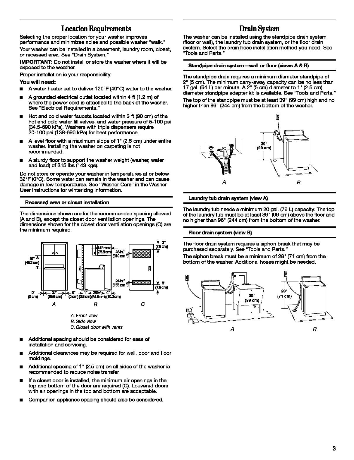
Recessed area or daset installation
The dimensions shown are for the recommended spacing allowed
(A and [3),except the closet door ventilation openings. The
dimensions shown for the closet door ventilation openings ((3) are
the minimum required.
A B
m _ 3"
(rscm)
D
_L3"
(7_cm)
m_
C
A. Front view
B. Side view
C. Closet door with vents
Additional spacing should be considered for ease of
installation and servicing.
Additional clearances may be required for wall, door and floor
moldings.
Additional spacing of 1" (2.5 cm) on all sides of the washer is
recommended to reduce noise transfer.
If e closet door is installed, the minimum air openings in the
top and bottom ofthe door are required ((3).Louvered doors
with air openings inthe top and bottom are acceptable.
Companion appliance spacing should also be considered.
Drain System
The washer can be installed using the standpipe drain system
(floor or wall), the laundry tub drain system, or the floor drain
system. Select the drain hose installation method you need. See
"Tools and Parts."
Standpipe drain system--wall or floor (views A & B)
The standpipe drain requires e minimum diameter standpipe of
2" (5 cm). The minimum carry-away capacity can be no lessthan
17 gal. (64 L) per minute. A 2" (5 cm) diameter to 1" (2.5 cm)
diameter standpipe adapter kit is available. See "Tools and Parts."
The top ofthe standpipe must be at least 39" (99 cro) high and no
higher than 96" (244 cm) from the bottom ofthe washer.
3g"
(99 cm)
A B
Laundry tub drain system (view A)
The laundry tub needs a minimum 20 gal. (76 I_)capacity. The top
of the laundrytub must be st least 39" (99 cm) above the floor and
no higherthan 96" (244 cm) from the bottom of the washer.
Roor drain system (view B)
The floor drain system requires a siphon break that may be
purchased separately. See "Tools and Parts."
The siphon break must be a minimum of 28" (71 cm) from the
bottom of the washer: Additional hoses might be needed.
A
B
ElectricalRequirements
Do not ground to a gas pipe.
Electrical Shock Hazard
Plug Into a grounded 3 prong outlet.
Do not remove ground prong.
Do not usa an adapter.
Do not usa an extension cord.
Failure to follow these Instructions can result In death,
fire, or electrical shock,
A 120-volt, 60-Hz., AC-only, 15- or 20-amp, fused electrical
supply is required. A time-delay fuse or circuit breaker is
recommended. It is recommended that a separate circuit
serving only this appliance be provided.
This washer isequipped with a power supply cord having a
3 prong grounding plug.
To minimize possible shock h_ard, the cord must be plugged
into a mating, 3 prong, grounding-type outlet, grounded in
accordance with local codas and ordinances. If a mating
outlet is not available, it is the personal responsibility and
obligation of the customer to have the properly grounded
outlet installed by a qualified electrician.
If codas permit and a separate ground wire is used, it is
recommended that a qualified electrician determine that the
ground path isadequate.
Check with a qualified electrician ifyou are not sure the
washer isproperly grounded.
Do not have a fuse inthe neutral or ground circuit.
GROUNDING INSTRUCTIONS
For a grounded, cord-connected washer:
This washer must be grounded. In the event or a malrunction
or breakdown, grounding will reduce the risk of electrical
shock by providing a path of least resistance forelectric
current. This washer is equipped with a cord having an
equipment-greunding conductor and a grounding plug.The
plug must be plugged intoan appropriate outlet that is
properly installed and grounded in accordance with all local
codes and ordinances.
WARNING: Improper connection of the equipment-
grounding conductor can result in a risk of electric shock.
Check with a qualified electrician or serviceman if you are in
doubt as to whether the appliance is properly grounded.
Do not modify the plug provided with the appliance - if it will
not fit the outlet, have a proper outlet installed by a qualified
electrician.
For a permanently connected washer:
This washer must be connected to a grounded metal,
permanent wiring system, or an equipment grounding
conductor must he run with the circuit conductors and
connected to the equipment-greunding terminal or lead on
the appliance.
4
INSTAM TIONINSTRUCTIONS
BeforeYouStart
4. Pullyellow shipping strap firmly, until both ends are
completely removed from washer.
NOTE: To prevent floor damage, set the washer onto cardboard
before moving across floor.
RemoveShippingStrap
Removing the shipping strap is necessary for proper operation. If
the shipping strap is not removed, the washer will make excessive
5. Check that the two (2) cotter pins were removed with the
shipping strap.
noise.
1. Move the washer to within approximately 3 ff (90 cm) of the
final location.
2. The washer must be inthe upright position and not tired
before removing the shipping strap.
3. Locate the yellow shipping strap on the rear of the machine
near the bottom.
I
.4_
q_, n
A. Yellow shipping strap
ConnectDrainBose
Proper connection of the drain hoes protects your floors from
damage due to water leakage. Carefully reed and follow these
instructions.
The drain hose is connected to your washer and is stored inside
the washer cabinet.
Remove drain hose from washer cabinet
Gently pull the corrugated drain hose out of the washer from the
top of the hose. Continue to pull the hose until the end emerges.
Do not force excess drain hose back into the rear of the washer.
Laundrytubdrainor standpipedrain
Connecting the drain hose form to the corrugated
drain hose
To prevent drain water from going back into the washen.
Do notforce excess drain hose into standpipe. Hose should
be secure but loose enough to provide a gap for ain
Do not lay excess hose on the bottom of the laundry tub.
Roor drain
Do not installthe drain hose form on to the corrugated drain hose.
You may need additional parts. See Floor Drain under "Tools and
Parts."
I.
ConnecttheInletHoses
Insert new fiat weshem (supplied) into each end of the inlet
hoses. Firmly seat the washers in the couplings.
A B
A. Coupling
B. Washer
Connect the inlet hoses to the water faucets
Make sure the washer basket isempty.
2. Attach the hoes labeled hat to the hot water faucet. Screw
on coupling by hand until it isseated on the washer.
3. Attach the hose labeled cold to the cold water faucet. Screw
on coupling by hand until it isseated on the washer.
4. Using pliers, tighten the couplings with an additional
two-thirds turn.
A B
A. Snap either end of the drain hose form to the drain hose at the
point where the corrugation begins.
B. Bend drain hose ever drain hose form and snap into place.
7-1ghtenthecouplingswithan additionaltwo-thirds turn.
NOTE: Do not overtightan or use tape or sealants on the
valve. Damage to the valves can result.
6
Clear the water lines
Runwater through both faucets and inlet hoses, into a laundry
tub, drainpipe or bucket, to get rid of particles in the water
lines that might clog the inlet valve screens.
Check the temperature of the water to make sure that the hot
water hose is connected to the hot water faucet and that the
cold water hoes is connected to the cold water faucet.
Connect the inlet hoses to the washer
A. Cold water inlet valve
B. Hot water inlet valve
1. Attach the hot water hose to the bottom inlet valve.
NOTE: Attaching the hot water coupling first makes it easier
to tighten connection with pliers.
2. Scraw on coupling by hand untilit isesated on the weshar.
4. Attach the cold water hose to the top inlet valve.
5. Screw on coupling by hand until it isseated on the washer.
6. Using pliers, tighten the couplings with an additional
two-thirds turn.
NOTE: Do not overtightan or use tape or sealants on the
valve. Damage to the valves can result.
Check for leaks
Turn onthe water faucets and check for leaks. A small amount
of water might enter the washer. You will drain this later.
NOTE: Replace inlet hoses after 5 years of use to reduce the
risk of hose failure. Record hose installation or replacement
dates for future reference.
Ifyou connect only one water hoes, you must cap off the
remaining water inlet port.
Periodically inspect and replace hoses if bulges, kinks,
cuts, wear, or leaks are found.
S Lre theDrainHose
1. Remove the shipping strap from the power cord. Drape the
power cord over the console.
2. Remove any cardboard used to move washer.
Beaded tie strap
3. Wrap the drain hose to the laundry tub leg or drain standpipe
with the beaded tie strap. Pushfastener into the nearest hole
in the beaded tie strap. See view A or B.
A B C
Ifthe washer faucets and the drain standpipe are recessed,
put the formed end of the drain hose into the standpipe.
_ghtly wrap the tie strap around the water inlet hoses and the
drain hose. See view C.
3,
Using pliers, tighten the couplings with an additional
two-thirds turn.
NOTE: Do not overtightan or use tape or sealants onthe
valve. Damage to the valves can result.
I vel the Washer
Propedy leveling your washer prevents excessive noise and
vibration. Steps in Final Location
Install the Front Leveling Feet
1.
2,
Prop up the front of the washer about 4" (10.2 cm) with a
wood block or similar object. The block needs to support the
weight of the washer.
4.
(10.2 cm)
A. Threaded holes for feet
1. Slide to final location.
2. "5Itthe washer forward untilthe rear of the washar isat least
4" (10.2 cm) off the floor. You may hear the self-adjusting rear
feet click into place. Lower the washer to the floor.
A
i A
V
(10.2 cm)
Screw the Iocknut onto each foot to within 1" (2.5 cm) of the
foot base.
A. Serf-adjustfeg feet
3. Check the levelnase of the washer by placing a level on the
top edges ofthe washer, first side to side, then front to back.
3, Screw the feet into the threaded holes at the front corner of
the washer untilthe nutstouch the washen Twist the foot to
install.
NOTE: Do not tighten the nuts untilthe washer is level.
4. Ifthe washer is not level, move the washer out slightly, tip
back, prop up the front of the washer with the wood block and
adjust the feet up or down as necessary by twisting the foot.
Turn the foot clockwise to raise the washer or
counterclockwise to lower the washer. Repeat steps
1through 4 until washer islevel.
5. After the washer is inthe final location and level, use a He" or
14 mm open-end wrench to turn the nuts counterclockwias on
the feet tightly against the washer cabinet.
IMPORTANT: Ifthe nuts are not tight against the washer
cabinet, the washer may vibrate.
4. _it the washer back and remove the wood block. Gently lower
the washer to the floor.
8
f,
2,
3,
4.
5,
6.
7.
Complete Installation
Check the electrical requirements. Be sure that you have the
correct electrical supply and the recommended grounding
method. See "Electrical Requirements."
Check to be sure all parts ere now installed. Ifthere isan extra
part, go beck through the steps to see which step was
skipped.
Check to be sure you have all of your tools.
Check to be sure that the yellow shipping strap was
completely removed from the lower beck of the washen
Dispose of or recycle all packaging materials.
Check to be sure the water faucets are on.
Check for leaks around faucets and inlet hoses.
Electrical Shock Hazard
Plug Into a grounded 3 prong outlet.
Do not remove ground prong.
Do not use an adapter.
Do not use an extension cord.
Failure to follow these Instructions can result In death,
fire, or electrical shock.
8. Plug into a grounded 3 prong outlet.
9. Remove the protective film on the console and any tape
remaining on the washer,
10. Read "Washer Use" inthe Washer User Instructions,
11. To test and to clean your washer, measure 1_ofthe normal
recommended amount of powdered or liquid detergent and
pour it intothe washer basket or detergent dispenser (on
some models). Close the lid. Select any cycle, and then pull
the cycle control knob out to start the washer. Allow itto
complete one whole cycle.
11/04
Printed in U.S.A.
3957165 Impreso an EE;UU.
© 2004 Whirlpool Corporation. Benton Harbor, Michigan 49022 Imprim_ aux E.-U.
  • Page 1 1
  • Page 2 2
  • Page 3 3
  • Page 4 4
  • Page 5 5
  • Page 6 6
  • Page 7 7
  • Page 8 8
  • Page 9 9
  • Page 10 10
  • Page 11 11
  • Page 12 12
  • Page 13 13
  • Page 14 14
  • Page 15 15
  • Page 16 16
  • Page 17 17
  • Page 18 18
  • Page 19 19
  • Page 20 20
  • Page 21 21
  • Page 22 22
  • Page 23 23
  • Page 24 24

Crosley 3957165 Installation guide

Category
Washing machines
Type
Installation guide

Ask a question and I''ll find the answer in the document

Finding information in a document is now easier with AI