Page is loading ...

US FCC Part 15 Class B Verification Statement
NOTE: This equipment has been tested and found to comply with the limits for a Class B digital
device, pursuant to Part 15 of the FCC Rules. These limits are designed to provide reasonable
protection against harmful interference in a residential installation. This equipment generates, uses
and can radiate radio frequency energy and, if not installed and used in accordance with the
instructions, may cause harmful interference to radio communications. However, there is no
guarantee that interference will not occur in a particular installation. If this equipment does cause
harmful interference to radio or television reception, which can be determined by turning the
equipment off and on, the user is encouraged to try to correct the interference by one or more of the
following measures:
● Reorient or relocate the receiving antenna.
● Increase the separation between the equipment and receiver.
● Connect the equipment into an outlet on a circuit different from that to which the receiver is
connected.
● Consult the dealer or an experienced radio/TV technician for help.

Page 1 MNNCEKRKB1_0439
INDEX
1 OPENING AND CHECKING THE PACKAGE..........................................................................................................7
1.1 Contents of the package .....................................................................................................................................7
1.2 Opening the package ..........................................................................................................................................7
1.3 Checking the markings........................................................................................................................................7
1.4 Marking Data.......................................................................................................................................................7
2 DESCRIPTION ..........................................................................................................................................................8
2.1 Specifications ......................................................................................................................................................8
2.1.1 Keyboard .......................................................................................................................................................................8
2.1.2 Set up ............................................................................................................................................................................8
2.1.3 Security..........................................................................................................................................................................8
2.2 Equipment that can be connected to the EKR-KB1 keyboard ............................................................................8
2.2.1 Video matrix...................................................................................................................................................................8
2.2.2 Video multiplexer ...........................................................................................................................................................8
2.2.3 Digital video recorder.....................................................................................................................................................9
2.2.4 Telemetry receivers and domes.....................................................................................................................................9
2.3 Keys and connectors...........................................................................................................................................9
2.4 Second function keys ........................................................................................................................................10
2.5 Dip switch ..........................................................................................................................................................10
3 COMMUNICATION LINES AND CONNECTIONS .................................................................................................11
3.1 Video and telemetry lines..................................................................................................................................11
3.2 RS485 and system types ..................................................................................................................................11
3.3 Standard connection cable................................................................................................................................12
3.4 One control keyboard per line...........................................................................................................................13
3.5 More than two devices on the same line...........................................................................................................13
4 KEYBOARD SETUP ...............................................................................................................................................14
4.1 Keys ..................................................................................................................................................................14
4.2 Selecting and inserting values ..........................................................................................................................14
4.3 Menu items........................................................................................................................................................14
4.4 Assigning the telemetry lines ............................................................................................................................16
4.5 Accepting requests for cameras and assigning receivers ................................................................................16
4.5.1 Default setting..............................................................................................................................................................17
4.5.2 Accepted cameras menu .............................................................................................................................................17
4.5.3 Assign receivers menu.................................................................................................................................................17
4.5.4 Modifying the list ..........................................................................................................................................................17
4.5.5 Notes concerning assigning the receivers ...................................................................................................................19
4.5.6 Warning message ........................................................................................................................................................19
4.6 Accepting the request for monitors ...................................................................................................................19
4.6.1 Default setting..............................................................................................................................................................19
4.6.2 Modifying the list ..........................................................................................................................................................19
4.7 Accepting the request for multiplexers..............................................................................................................20
4.7.1 Default setting..............................................................................................................................................................20
4.7.2 Modifying the list ..........................................................................................................................................................20
4.8 Accepting requests for functions .......................................................................................................................20
4.9 Joystick calibration and test ..............................................................................................................................21
4.10 Buzzer .............................................................................................................................................................22
4.11 Password.........................................................................................................................................................22
4.12 Warning and error messages..........................................................................................................................22
4.13 Autotest of serial channels ..............................................................................................................................23
4.13.1 Autotest procedure.....................................................................................................................................................23
4.14 Macro Protocol: special functions ...................................................................................................................24
4.14.1 Description.................................................................................................................................................................24
4.14.2 Special functions featured by Macro protocol ............................................................................................................24

Page 2 MNNCEKRKB1_0439
5 VIDEO MANAGEMENT ..........................................................................................................................................25
5.1 Description of the display ..................................................................................................................................25
5.2 Video: fundamental concepts............................................................................................................................25
5.2.1 Direct selection of a camera ........................................................................................................................................25
5.2.2 Selecting the previous/next camera.............................................................................................................................26
5.2.3 Everfocus DVR Control................................................................................................................................................26
5.2.4 “Views”.........................................................................................................................................................................27
5.2.5 Receivers associated with the cameras.......................................................................................................................28
5.3 Video matrix Eneo EKR-32/8 ............................................................................................................................29
5.3.1 Description...................................................................................................................................................................29
5.3.2 Connection...................................................................................................................................................................29
5.3.3 Video device setup.......................................................................................................................................................29
5.4 Video matrix Videotec SM328A ........................................................................................................................30
5.4.1 Description...................................................................................................................................................................30
5.4.2 Connection...................................................................................................................................................................30
5.4.3 Video device setup.......................................................................................................................................................30
5.5 Video matrix Eneo EKR-8/4 and EKR-16/4 ......................................................................................................31
5.5.1 Description...................................................................................................................................................................31
5.5.2 Connexion....................................................................................................................................................................31
5.5.3 Video device setup.......................................................................................................................................................31
5.6 Video matrix Videotec SM84A and SM164A ....................................................................................................32
5.6.1 Description...................................................................................................................................................................32
5.6.2 Connexion....................................................................................................................................................................32
5.6.3 Video device setup.......................................................................................................................................................32
5.7 Switchers Videotec SM42A and SM82A...........................................................................................................33
5.7.1 Description...................................................................................................................................................................33
5.7.2 Connection...................................................................................................................................................................33
5.7.3 Video device setup.......................................................................................................................................................33
5.8 Video matrix Linxs LXRPS84A and LXRPS164A .............................................................................................34
5.8.1 Description...................................................................................................................................................................34
5.8.2 Connection...................................................................................................................................................................34
5.8.3 Video device setup.......................................................................................................................................................35
5.9 Switchers Linxs LXRPS42A and LXRPS82A....................................................................................................36
5.9.1 Description...................................................................................................................................................................36
5.9.2 Connection...................................................................................................................................................................36
5.9.3 Video device setup.......................................................................................................................................................37
5.10 Video matrix Videotec SW328 ........................................................................................................................38
5.10.1 Description.................................................................................................................................................................38
5.10.2 Connection.................................................................................................................................................................38
5.10.3 Matrix setup ...............................................................................................................................................................38
5.11 Video matrix Videotec SW164OSM ................................................................................................................39
5.11.1 Description.................................................................................................................................................................39
5.11.2 Connection.................................................................................................................................................................39
5.11.3 Matrix setup ...............................................................................................................................................................41
5.12 Video multiplexer Eneo ...................................................................................................................................42
5.12.1 Description.................................................................................................................................................................42
5.12.2 Direct connection .......................................................................................................................................................42
5.12.3 Dedicated functions ...................................................................................................................................................43
5.13 Video multiplexer Javelin ................................................................................................................................44
5.13.1 Description.................................................................................................................................................................44
5.13.2 Direct connection .......................................................................................................................................................44
5.13.3 Dedicated functions ...................................................................................................................................................45
5.14 Video multiplexer Videotec SP16C .................................................................................................................46
5.14.1 Description.................................................................................................................................................................46
5.14.2 Connexion..................................................................................................................................................................46
5.14.3 Dedicated functions ...................................................................................................................................................47
5.15 Controlling the multiplexer using a video device.............................................................................................48
5.15.1 Selecting a monitor connected to the video matrix.....................................................................................................48
5.15.2 Selecting a monitor connected to the multiplexer.......................................................................................................48
5.16 Sony video multiplexer ....................................................................................................................................49
5.16.1 Description.................................................................................................................................................................49
5.16.2 Materials and reference documents...........................................................................................................................49

Page 3 MNNCEKRKB1_0439
5.16.3 Direct connection .......................................................................................................................................................49
5.16.4 Configuration .............................................................................................................................................................50
5.16.5 Dedicated Functions ..................................................................................................................................................50
5.17 Sony DVR........................................................................................................................................................52
5.17.1 Description.................................................................................................................................................................52
5.17.2 Materials and reference documents...........................................................................................................................52
5.17.3 Direct connection .......................................................................................................................................................52
5.17.4 Configuration .............................................................................................................................................................53
5.17.5 Special SEARCH menu .............................................................................................................................................53
5.17.6 Special COPY menu ..................................................................................................................................................53
5.17.7 Dedicated Functions ..................................................................................................................................................53
5.18 Ademco multiplexer.........................................................................................................................................55
5.18.1 Description.................................................................................................................................................................55
5.18.2 Direct connection .......................................................................................................................................................55
5.18.3 Dedicated functions ...................................................................................................................................................56
5.19 Sanyo multiplexer............................................................................................................................................57
5.19.1 Description.................................................................................................................................................................57
5.19.2 Materials and reference documents...........................................................................................................................57
5.19.3 Direct connection .......................................................................................................................................................57
5.19.4 Configuration .............................................................................................................................................................58
5.19.5 Dedicated Functions ..................................................................................................................................................58
5.19.6 Choice of protocol ......................................................................................................................................................59
5.19.7 Indications on the display...........................................................................................................................................59
5.20 Everfocus DVR................................................................................................................................................60
5.20.1 Description.................................................................................................................................................................60
5.20.2 Connections...............................................................................................................................................................60
5.20.3 DVR Configuration .....................................................................................................................................................60
6 TELEMETRY CONTROL ........................................................................................................................................61
6.1 Controlling the telemetry directly and using video systems ..............................................................................61
6.2 Common telemetry operations..........................................................................................................................62
6.2.1 Changing the active receiver .......................................................................................................................................62
6.3 Communication problems between keyboard and receiver..............................................................................62
6.4 Notes regarding telemetry control.....................................................................................................................63
6.4.1 Special codes ..............................................................................................................................................................63
6.4.2 Typographical conventions ..........................................................................................................................................63
6.5 Elbex Dome.......................................................................................................................................................64
6.5.1 Reference material and documents .............................................................................................................................64
6.5.2 Notes on protocol.........................................................................................................................................................64
6.5.3 Connection...................................................................................................................................................................64
6.5.4 Dome setup .................................................................................................................................................................64
6.5.5 Note on dome control...................................................................................................................................................64
6.5.6 Dome movement..........................................................................................................................................................65
6.5.7 Autopan .......................................................................................................................................................................65
6.5.8 Movement limits...........................................................................................................................................................65
6.5.9 Preset, scan, home......................................................................................................................................................65
6.5.10 Auto scan control .......................................................................................................................................................66
6.5.11 Timers........................................................................................................................................................................66
6.5.12 Lenses .......................................................................................................................................................................67
6.5.13 Auxiliary Relays .........................................................................................................................................................69
6.5.14 Other functions...........................................................................................................................................................69
6.6 Elmo Dome........................................................................................................................................................70
6.6.1 Reference material and documents .............................................................................................................................70
6.6.2 Connection...................................................................................................................................................................70
6.6.3 Setup ...........................................................................................................................................................................70
6.6.4 Autopan .......................................................................................................................................................................72
6.6.5 Preset, scan, home......................................................................................................................................................72
6.6.6 Sequences and Cruise.................................................................................................................................................72
6.6.7 Other functions.............................................................................................................................................................72
6.7 Eneo Fastrax II Dome .......................................................................................................................................73
6.7.1 Material and reference documents...............................................................................................................................73
6.7.2 Connection...................................................................................................................................................................73
6.7.3 Configuration ...............................................................................................................................................................73
6.7.4 Preset, scan, home......................................................................................................................................................74

Page 4 MNNCEKRKB1_0439
6.7.5 Autoscan, Patrol and Pattern .......................................................................................................................................74
6.8 Eneo Pan & Tilt .................................................................................................................................................75
6.8.1 Materials and reference documents.............................................................................................................................75
6.8.2 Connections.................................................................................................................................................................75
6.8.3 Configuring the pan & tilt..............................................................................................................................................75
6.8.4 Autopan .......................................................................................................................................................................76
6.8.5 Preset, scan, home......................................................................................................................................................76
6.8.6 Patrol ...........................................................................................................................................................................76
6.8.7 Auxiliary relays.............................................................................................................................................................77
6.8.8 Positioning limits ..........................................................................................................................................................77
6.8.9 Other functions.............................................................................................................................................................77
6.9 Ernitec Saturn Dome.........................................................................................................................................78
6.9.1 Reference material and documents .............................................................................................................................78
6.9.2 Connection...................................................................................................................................................................78
6.9.3 Setup ...........................................................................................................................................................................78
6.9.4 Autopan .......................................................................................................................................................................79
6.9.5 Preset, scan, patrol and home .....................................................................................................................................79
6.9.6 Auxiliary relays.............................................................................................................................................................80
6.9.7 Lenses .........................................................................................................................................................................80
6.9.8 Return position.............................................................................................................................................................80
6.9.9 Other special codes .....................................................................................................................................................80
6.10 JVC TK-C675 Dome .......................................................................................................................................81
6.10.1 Reference material and documents ...........................................................................................................................81
6.10.2 Connection.................................................................................................................................................................81
6.10.3 Setup .........................................................................................................................................................................81
6.10.4 Autopan .....................................................................................................................................................................82
6.10.5 Preset, home, scan ....................................................................................................................................................82
6.10.6 Patrol .........................................................................................................................................................................83
6.10.7 Other commands and special codes..........................................................................................................................83
6.11 JVC TK-C676 Dome .......................................................................................................................................84
6.11.1 Reference material and documents ...........................................................................................................................84
6.11.2 Hardware connection to the dome .............................................................................................................................84
6.11.3 Dome settings............................................................................................................................................................84
6.11.4 Setup .........................................................................................................................................................................84
6.11.5 Added functions .........................................................................................................................................................84
6.11.6 Preset, home, scan ....................................................................................................................................................84
6.11.7 Auxiliary contacts.......................................................................................................................................................84
6.11.8 Other functions...........................................................................................................................................................85
6.11.9 Zoom e focus .............................................................................................................................................................85
6.12 Panasonic Dome.............................................................................................................................................86
6.12.1 Reference material and documents ...........................................................................................................................86
6.12.2 Important protocol note ..............................................................................................................................................86
6.12.3 Connection.................................................................................................................................................................86
6.12.4 Setup .........................................................................................................................................................................87
6.12.5 Autopan .....................................................................................................................................................................87
6.12.6 Autopan functions for WV-CS850 model ...................................................................................................................87
6.12.7 Limit movement for WV-CS850 model.......................................................................................................................88
6.12.8 Preset, scan, home ....................................................................................................................................................88
6.12.9 Patrol Setup for the WV-CS850 model ......................................................................................................................88
6.12.10 Patrol setup for WV-CS600 model ...........................................................................................................................88
6.12.11 Shutter and Electronic sensitivity setup ...................................................................................................................88
6.12.12 Autoflip.....................................................................................................................................................................89
6.12.13 Lenses and flip.........................................................................................................................................................89
6.12.14 Relè (only WV-CS850 model)..................................................................................................................................89
6.12.15 Other functions (only WV-CS850 mode)..................................................................................................................90
6.13 Pelco Dome.....................................................................................................................................................91
6.13.1 Reference material and documents ...........................................................................................................................91
6.13.2 Connection.................................................................................................................................................................91
6.13.3 Setup .........................................................................................................................................................................91
6.13.4 Preset, scan, home ....................................................................................................................................................91
6.13.5 Pattern .......................................................................................................................................................................92
6.13.6 Zone...........................................................................................................................................................................92
6.13.7 Lenses .......................................................................................................................................................................92
6.13.8 Relays and alarms .....................................................................................................................................................92
6.13.9 Other functions...........................................................................................................................................................93

Page 5 MNNCEKRKB1_0439
6.13.10 Speed Factors..........................................................................................................................................................93
6.14 Samsung Dome ..............................................................................................................................................94
6.14.1 Reference material and documents ...........................................................................................................................94
6.14.2 Connection.................................................................................................................................................................94
6.14.3 Setup .........................................................................................................................................................................94
6.14.4 Autopan .....................................................................................................................................................................95
6.14.5 Preset, scan, home, patrol .........................................................................................................................................95
6.14.6 Pattern .......................................................................................................................................................................96
6.14.7 Other functions...........................................................................................................................................................96
6.15 Santec Dome ..................................................................................................................................................97
6.15.1 Connection.................................................................................................................................................................97
6.15.2 Configuration .............................................................................................................................................................97
6.15.3 Preset, scan, home ....................................................................................................................................................98
6.15.4 Autoscan, Patrol and Pattern .....................................................................................................................................98
6.16 Sensormatic / American Dynamics Dome ......................................................................................................99
6.16.1 Reference material and documents ...........................................................................................................................99
6.16.2 Connection.................................................................................................................................................................99
6.16.3 Setup .........................................................................................................................................................................99
6.16.4 Preset, scan, home ..................................................................................................................................................100
6.16.5 Pattern and “apple peel” ..........................................................................................................................................100
6.16.6 Relays......................................................................................................................................................................100
6.16.7 Other functions.........................................................................................................................................................101
6.17 Star Dome .....................................................................................................................................................102
6.17.1 Reference material and documents .........................................................................................................................102
6.17.2 Connection...............................................................................................................................................................102
6.17.3 Preset, scan, home ..................................................................................................................................................102
6.17.4 Autopan, patrol, tour ................................................................................................................................................102
6.17.5 Setup .......................................................................................................................................................................105
6.17.6 Other functions.........................................................................................................................................................105
6.18 VCL Dome.....................................................................................................................................................106
6.18.1 Reference material and documents .........................................................................................................................106
6.18.2 Connection...............................................................................................................................................................106
6.18.3 Setup .......................................................................................................................................................................106
6.18.4 Preset, scan, home ..................................................................................................................................................106
6.18.5 Autopan and tour .....................................................................................................................................................107
6.18.6 Camera setup ..........................................................................................................................................................108
6.18.7 Lenses .....................................................................................................................................................................108
6.18.8 Other functions.........................................................................................................................................................108
6.19 Videotec and Linxs receivers ........................................................................................................................109
6.20 Videotec and Linxs receivers with Videotec protocol....................................................................................110
6.20.1 Reference material...................................................................................................................................................110
6.20.2 Connexion................................................................................................................................................................110
6.20.3 Preset, scan, home ..................................................................................................................................................110
6.20.4 Autopan ...................................................................................................................................................................110
6.20.5 Patrol .......................................................................................................................................................................111
6.20.6 Relays......................................................................................................................................................................111
6.20.7 Other functions.........................................................................................................................................................111
6.21 Videotec Receivers with Macro protocol.......................................................................................................112
6.21.1 Note .........................................................................................................................................................................112
6.21.2 Reference material and documents .........................................................................................................................112
6.21.3 Connection...............................................................................................................................................................112
6.21.4 Setup .......................................................................................................................................................................112
6.21.5 Autopan ...................................................................................................................................................................112
6.21.6 Preset, scan, home ..................................................................................................................................................113
6.21.7 Patrol .......................................................................................................................................................................113
6.21.8 Relays......................................................................................................................................................................114
6.21.9 Lenses .....................................................................................................................................................................114
6.21.10 Other functions.......................................................................................................................................................114
7 MAINTENANCE ....................................................................................................................................................115
8 SPECIFICATIONS.................................................................................................................................................116

Page 6 MNNCEKRKB1_0439
The manufacturer declines all responsibility for any damage caused by an improper use of the appliances
mentioned in this manual; furthermore, the manufacturer reserves the right to modify its contents without any
prior notice. The documentation contained in this manual has been collected with great care: the manufacturer,
however, cannot take any liability for its use. The same thing can be said for any person or company involved in
the creation and production of this manual.

Page 7 MNNCEKRKB1_0439
1 Opening a nd checking the package
The following procedures should be carried out before connecting to the power supply, unless indicated
otherwise.
Installation should only carried out by skilled technical personnel.
1.1 Contents of the package
When the product is delivered, make sure the package is intact and has no obvious signs of dropping scrapes
or scratches. If the package is damaged contact the supplier immediately.
• 1 EKR-KB1 keyboard
• 1 external power supply
• 6 telephone cables 6/6 point-to-point, length 150 cm approx.
• 6 RJjack shunt boxes
• this user’s manual
Make sure the contents correspond to the materials listed above.
1.2 Opening t he package
If the package has no obvious defect due to dropping or abnormal scrapes and scratches, check the materials it
contains with the list supplied in the previous paragraph.
The technician will be responsible for disposing of the packaging material by recycling or, in any case, according
to the current legislation in the country of use.
1.3 Checking the markings
Before proceeding with the installation, check the marking labels to make sure the supplied material
corresponds to the required specifications as described in the next paragraph. Never, under any circumstances
make any changes or connections that are not described in this manual: the use of inappropriate equipment
may be very dangerous for the safety of personnel and the system itself.
1.4 Marking D ata
A label, conformed to CE markings, is placed on the lower side of the EKR-KB1 keyboard.
It contains the identification code of the model (Barcode EXT3/9).and indicates the serial number of the model
(Barcode EXT3/9).
When you are ready to install, check if the characteristics of the keyboard’s power supply correspond to the
requested ones. The use of unsuitable equipment can be cause of safety hazards to personnel and to the
system itself.

Page 8 MNNCEKRKB1_0439
2 Descriptio n
2.1 Specifica tions
The EKR-KB1 keyboard is a product for professional use in applications for security and surveillance.
In a security system the keyboard is used to control video switching, to manage alarm conditions should they
occur and for remote control of digitally controlled receivers.
2.1.1 Keyboard
Backlighted LCD with 4 lines of 20 characters for controlling operations
Ergonomic key configuration
Easy to use: the most commonly used operations are activated by pressing a single key
Telemetry control by joystick
2.1.2 Set up
Complete keyboard on display setup
National language selection
Control of a wide range of high speed domes and receivers
Input and output enabling/disabling can be controlled by each keyboard
Enabling/disabling of groups of keys
Autotest of communication channels
RS485 communication lines.
2.1.3 Security
Buzzer for breaks in communication and alarm
3 password levels, which can be set up individually within each keyboard:
• connection password: requested when the keyboard is switched on, to prevent use by unauthorised
personnel;
• alarm reset password: requested when alarm is cleared from the keyboard;
• setup password: requested when setup is required (of either the keyboard or the matrix).
Every password consists of a series of 5 digits and can be disabled if set to 00000.
2.2 Equipmen t that can be connected to the EKR-KB1 keyboard
2.2.1 Video matr ix
Eneo EKR-32/8
Eneo EKR-8/4, EKR-16/4
Videotec SM328A
Videotec SM42A, SM82A
Videotec SM84A, SM164A
Videotec SW328
Videotec SW164OSM (con adattatore di linea RS232 - RS485)
LXRPS42A, LXRPS42TA
LXRPS82A, LXRPS82TA
LXRPS84A
LXRPS164A
2.2.2 Video multi plexer
Eneo color and B/W model VCMT-8009/80016 / VBMT-8009/80016
Videotec SP16C
Javelin color and B/W model JPMCD16X / JPMMD16X
Multiplexer Sony YS-DX516P
Multiplexer Ademco DVR AHDR4 / DVR AHDR9 / AHDR16
Multiplexer Sanyo MPX-CD93P / MPX-CD163P

Page 9 MNNCEKRKB1_0439
2.2.3 Digital vide o recorder
Sony HSR-X216P
Everfocus EDSR AND EDSR/H
2.2.4 Telemetry r eceivers and domes
DTRX1
DTRX3
DTMRX1
DTRXDC
MICRODEC485
Dome Elbex EX/EXC 8000 Instant Dome
Dome Elmo D7720B
P&T Eneo VPT-42/RS1
Dome Eneo Fastrax II
Dome Ernitec Saturn
Dome Fastrax II (HID-2404)
Dome Jvc TK-C675, -C676
Dome Panasonic 600 and Panasonic 850
Dome Pelco Spectra and Spectra Lite
Dome Samsung SCC64-1P – SCC643P
Dome Santec
Dome Sensormatic DeltaDome
Dome Star
Dome Vcl VC5S-ORBM
2.3 Keys and connectors
The keys are grouped according to their function:
keys for video management V
keys for telemetry management T
function keys F
The EKR-KB1 keyboard has three RJ11 connectors
on the back of the mechanical part, a power supply
connector, dip-switches for setup and a DB9
connector to update the firmware when necessary.
The VIDEO line controls the video system connected
to the keyboard. Lines A and B control the first and
second telemetry channel respectively.
The dip switches are used to insert or remove the
120 ohm termination load for each of the RS485 lines
(see § RS485 and system types, page 11)

Page 10 MNNCEKRKB1_0439
2.4 Second fu nction keys
Some keys (, , ) can be used to activate second functions if pressed simultaneously with other
keys.
For example,
means: press the key followed by the key, keeping pressed down.
The keys can be released in any order.
2.5 Dip switc h
The back of the keyboard has a set of dip-switches that are used to insert/remove the load of the RS485 lines
and block keyboard programming from the PC. Refer to § 3.1 - Video and telemetry lines, page 11, for further
information about inserting the line loads.
ON: load inserted
DIP4: load on Video line
OFF: load removed
ON: load inserted
DIP3: load on Telemetry B line
OFF: load removed
ON: load inserted
DIP2: load on Telemetry A line
OFF: load removed
ON: update is possible
DIP1: internal firmware update
OFF: update is not possible

Page 11 MNNCEKRKB1_0439
3 Communi cation lines and connections
3.1 Video and telemetry lines
The EKR-KB1 keyboard can be used to control a wide range of products, for both video control (video matrixes
and multiplexers) and telemetry control (receivers and domes). It is therefore necessary to define the system
structure at the keyboard level to achieve efficient communication between the connected devices.
“Video line” means the communication channel intended to control the video devices; “telemetry lines” means
the two channels available for telemetry control.
We advise starting with the setup of the single “video line” and after that passing to the setup of the “telemetry
lines”.
3.2 RS485 an d system types
The RS485 communication channels are 2-wire lines whose maximum length from end to end is 1200m.
The termination of the RS483 lines prevents signal reflection along the cable and should be inserted in each of
the devices that forms the end of a connection.
Systems can be of different types, therefore the way of terminating the lines will also be different.
In the diagrams shown below, the devices requiring termination are indicated by the # symbol.
Setup Description Example
Star /
Single lines
For each connection between two
devices there should be a separate
communication line, with a maximum
length of 1200m.
All devices should be terminated, since
each device is connected to an end of
the line
Backbone A single line is used, and the
transmitters can be placed in any
position along it. The two ends of the
line (keyboard K and receiver R3 in the
example) are terminated; the other
devices (R1 and R2) are not
terminated. The maximum length of the
line is 1200m.
The specifications for the RS485
standard allow at least 32 devices to be
connected along the same line.
Line with stub A certain number of stubs can be
shunted in parallel to the normal RS485
line, for connection to other devices.
Since the stubs are not at the ends of
the line, they should not be terminated
and they should be very short in length
(of the order of a couple of metres).
The specifications for the RS485
standard allow at least 32 devices to be
connected along the same line.

Page 12 MNNCEKRKB1_0439
Setup Description Example
Devices in a
chain
The devices are connected in pairs
using single lines. These should be
terminated at the ends. This type of
setup can only be made when the
devices have a separate input
(reception) and output (transmission)
channel, like the Videotec DTRX1 and
DTRX3 receivers.
The received signal is sent “clean” to
the next device. If one device is
blocked, communication is cut off to the
devices later in the chain.
The maximum total length is equal to
the number of lines multiplied by
1200m for each distance.
Mixed setup It is possible to set up mixed
configurations, always bearing in mind
the limits given above:
each line can have a maximum length
of 1200m
each line should be terminated at the
ends
the stubs should be very short (max.
2m)
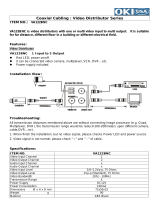
3.3 Standard connection cable
The connection between the EKR-KB1 keyboard and the various controlled devices is made only and
exclusively using a RS485 serial channel.
When the controlled device does not provide this channel it will be necessary to insert a signal converter (e.g.
RS486-RS232 or RS485- Current loop) between the keyboard and the device itself.
Connection with the latest generation of Videotec products (video switchers SM42A, SM82A, video matrix
SW328, EKR-8/4, EKR-16/4, etc.) can be made directly using a serial 1.5m telephone cable, which is supplied.
A pair of telephone cables with a pair of RJjack shunt boxes can be used to arrive at distances of up to 1200m
using the following connection diagram:
RJ
j
ack1 RJ
j
ack2
L=1200 m
EKR-KB1 RJjack 1 RJjack 2 Device
RS485A White Blue RS485A
RS485B Yellow Black RS485B

Page 13 MNNCEKRKB1_0439
3.4 One contr ol keyboard per line
Connection is performed by means of one standard connection cable, which is described in the previous
paragraph.
3.5 More than two devices on the same line
The presence of more than one keyboard on the same communication line requires the use of Rjjack boxes, to
be connected in the correct way. As specified in § 3.2 RS485 and system types, page 11, identify the two
devices which represent the line ends and correctly terminate them (to terminate the EKR-KB1 keyboard, see §
2.5 - Dip switch, page 10).
Particular attention must be paid for the length of the stubs.
Transmitters (keyboards) Receivers
(video matrixes, telemetry)
White
RS485A
Blue
Yellow
RS485B
Black

Page 14 MNNCEKRKB1_0439
4 Keyboard setup
Programming is carried out on the keyboard display. The following is a description of the procedure to start
programming the various menu items shown on the display.
4.1 Keys
To enter setup:
To move the cursor within the menus:
choose the line with the joystick
change the value with the joystick
enter the submenu indicated by the cursor
exit to previous menu
To exit setup: press
repeatedly.
4.2 Selecting and inserting values
When a menu allows multiple choices, the selected item is indicated by the symbol.
If a numeric value is to be inserted, it should be confirmed by
. can be used to erase the last digit
inserted, and
to exit without saving. If the numeric value is invalid, an acoustic signal will warn the
operator of the error.
The individual menu items are not displayed when the previous choices make them unnecessary.
4.3 Menu item s
Shown on display Submenu Description
Choice of menu and message language.
The selected language is indicated by the *
symbol.
Definition of devices connected to the
keyboard, see § 2.2 - Equipment that can
be connected to the EKR-KB1 keyboard,
page 8
Parameters for video line; see § 5 - Video
management, page 25
Parameters for telemetry line A; see § 6.3 -
Communication problems between
keyboard and receiver, page 62
Parameters for telemetry line B; see § 6.3 -
Communication problems between
keyboard and receiver, page 62
Acceptance of requests for
cameras/receivers, monitors, functions and
multiplexers. Acceptance is a very practical
way of limiting keyboard operations,
without having to make use of further
system passwords

Page 15 MNNCEKRKB1_0439
Shown on display Submenu Description
Accepting the request for individual and
assigns receivers to the cameras; see §
4.5 - Accepting requests for cameras and
assigning receivers, page 16
Accepting the request for individual
monitors see § 4.6 - Accepting the request
for monitors, page 19
Accepting the request for functions;
see § 4.8 - Accepting requests for
functions, page 20
Accepting the request for individual
multiplexers; see § 4.7 - Accepting the
request for multiplexers, page 20
System identification number of keyboard.
Each keyboard in the system should be
identified by a different number: the
presence of more than one keyboard with
the same number could cause
communication problems.
Joystick calibration and test
see § 4.9 - Joystick calibration and test,
page 21
Activation of warning buzzer;
see § 4.10 - Buzzer, page 22
Definition of keyboard passwords;
see § 4.11 - Password, page 22
Concealed password insertion
Concealed password confirmation

Page 16 MNNCEKRKB1_0439
Shown on display Submenu Description
Power saving puts the keyboard in low
consumption mode after one minute of
inactivity.
Management of warning and error
messages;
see § 4.12 - Warning and error messages,
page 22
Autotest of serial channels
see § 4.13 - Autotest of serial channels,
page 23
Joystick operation test.
The test is described at § 4.9 - Joystick
calibration and test, page 21
Internal memory test, useful in the case of
faulty operation and telephone assistance.
Changes display contrast: press and
to alter contrast.
recalls the previous contrast value
and
recalls the default value.
Resets factory default values. The reset
operation should be confirmed by the
operator.
Saves new settings and exits menu.
4.4 Assigning the telemetry lines
Assigning the telemetry lines has been inserted in the menu for accepted cameras. See the next section.
4.5 Accepting requests for cameras and assigning receivers
Accepting requests for cameras allows keyboard use to be limited solely to authorised input videos without
having to use further system passwords. We recommend defining the accepted input video groups for each
keyboard only after clearly defining the system configuration.
For each camera, in this menu it is necessary to define:
• acceptance of the camera when recalled by the keyboard
• the receiver/dome number (if present) to which the camera is connected
• the telemetry line (A or B) to which the corresponding receiver/dome is connected.

Page 17 MNNCEKRKB1_0439
4.5.1 Default sett ing
The default setting allows control of all cameras, erasing any previously defined setting.
To each camera is assigned a receiver identified by the same number (camera 1, receiver 1; camera 2, receiver
2, etc.) and all receivers are controlled by line A.
4.5.2 Accepted c ameras menu
The accepted cameras menu is used to determine which cameras can be recalled by the keyboard.
Select
to enter the submenu.
The four available items are:
•
: all cameras from 1 to 9999 are accepted.
•
: all cameras are disabled.
•
: a set of cameras is accepted. The number inserted first should be lower than the
second.
•
: a set of cameras is disabled. The number inserted first should be lower than the
second.
4.5.3 Assign rece ivers menu
The assign receivers menu defines which cameras have a receiver/dome.
Select
to enter the submenu.
• The five available items are:
a receiver is assigned to every camera
•
all cameras are defined as “no pan & tilt”.
•
: receivers are assigned only if the corresponding camera is accepted; all
receivers for which the camera is disabled are removed.
•
: a set of receivers is assigned.The camera number inserted first should be lower than
the second.
•
:a set of receivers is disabled.The camera number inserted first should be lower than
the second.
Notes:
• The assigned receiver number corresponds to that of the corresponding camera without the thousands digit.
• When it is possible to choose between two different telemetry lines, insert the line on which the receivers are
connected. All receivers comprising an interval are assigned to the same telemetry line.
4.5.4 Modifying t he list
After using the two previous menus for the overall definitions it is possible to modify individual items for a more
precise definition of the list of cameras that can be requested by the keyboard and of the receivers assigned to
them.
The modify list menu displays the various sets of cameras to be set up:
It is important to note the three special symbols on the right of the display:
indicates that no camera in the corresponding set is accepted
indicates that some cameras in the set are accepted and some are not
indicates that all cameras in the set are accepted.
There are 9999 cameras available: normally a much smaller set of cameras will be used but the possibility of
selection over a wide interval is useful for video management with large sized devices where the “zone” feature
is available.
The display in the example shows three sets of cameras: the first from number 1 to number 1000; the second
from number 1001 to 2000, the third from 2001 to 3000.
The other groups of cameras can be selected by moving the joystick
.
The cursor
shows the set of cameras being set up:
• to accept the request for all the cameras in the set press
.
• to disable all the cameras in the set press
.

Page 18 MNNCEKRKB1_0439
• if the set of accepted cameras is to be defined more precisely (some cameras in the set should be accepted
and others not), press
to subdivide the set shown into smaller sets.
• press
to return to the previous display menus.
The following example shows how to accept cameras 1 to 7, and at the same time disable access to all the
others. To camera 3 is assigned receiver 12 connected to telemetry line B::
All cameras in the 1-1000 set are accepted, while those from
1001 to 3000 are not. Select the 1-1000 set with the joystick
and press to completely disable all cameras.
The icons on the right of the display show that none of the
cameras in the sets from 1 to 3000 are now available on request.
Select the 1-1000 set with the joystick
and press to pass
to a more precise definition level.
The sets shown on the display are now of 100 cameras each.
None of the cameras in the sets are accepted.
Select the 1-100 set with
and press to pass to a more
precise definition level.
Select the 1-10 set and press to accept all cameras in the
set from 1 to 10.
Then press
to define acceptance at the individual camera level.
The menu changes to allow precise definition of the individual
cameras.
Given that all cameras from 1 to 10 are now accepted, it is
necessary to scroll the list with the joystick to disable cameras
8,9,10, as required in the example.
Scroll the list with
until camera 8 is reached.
The heading on the first line means:
•
: camera number
•
: the camera can or cannot be selected from the
keyboard
•
: number of receiver/dome assigned to the camera
: control line (A or B) for the receiver/dome
Press
to disable camera 8. Disabling the camera will
automatically remove the receiver number and the corresponding
telemetry line.
Continue in the same way to disable cameras 9 and 10.

Page 19 MNNCEKRKB1_0439
Normally camera with pan & tilt is assigned a receiver/dome with the
same number (camera 1, receiver 1, camera 2, receiver 2, etc.)
Under particular circumstances (while installing composit
systems for example) it may be necessary to assign a receiver
with a different number from that of the camera.
In the example given receiver 12 is to be assigned to camera 3,
and the receiver should be controlled on telemetry line B.
Scroll the list to find the camera to have a new setting and press
to proceed with the change.
The column shows a cursor: it is expecting insertion of the
receiver/dome number assigned to the camera. Press
to assign receiver 12.
After inserting the receiver number, if the keyboard is set up to
control two different telemetry protocols the menu will ask on
which line (A or B) the receiver is connected.
Press
to assign line A, for line B.
After completing modification, pressing will return to the
previous menu and then again on up to the main menu.
The icon of the 1-10 set has now been changed to
to show that
only some of the cameras in the group are now accepted.
4.5.5 Notes conc erning assigning the receivers
After the receivers have been assigned in the menu, the key will be automatically disabled (if it is to be re-
enabled see § 4.5 - Accepting requests for cameras and assigning receivers, page 16
4.5.6 Warning m essage
If a disabled camera is requested, the display will show a message warning the operator that the request is not
authorised:
4.6 Accepting the request for monitors
Accepting the monitors is used to prevent an unauthorised operator from operating monitors that are not within
his duties.
4.6.1 Default sett ing
The default setting allows control of all monitors, erasing any previously defined setting.
4.6.2 Modifying t he list
The procedure for accepting and disabling the monitors is the same as that just described for the cameras (see
§ 4.5 - Accepting requests for cameras and assigning receivers, page 16).
Usually 99 monitors can be selected from the keyboard.
/