Fagor 5CFB-36 IX User manual
- Category
- Cooker hoods
- Type
- User manual
This manual is also suitable for
Page is loading ...
Page is loading ...
Page is loading ...

Warnings
Uses
Installation
Working
Maintenance
CONTENTS
4
GB

5
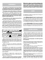
* The appliance is not intended for use by young children
or infirm persons without supervision. Young children should
be supervised to ensure they do not play with the appliance.
* The cooktop surface and the inferior part of the range
hood must be at a minimun distance of 65 cm.
* The air sucked can't be vented through or into a duct
used to let out fumes from appliances fed by energy
other than electric power (eg. centralized heating,
radiators, water-heaters, etc.).
* To evacuate the air outlet, please comply with the
pertaining rules given by authorities.
* Provide the room with an adequate aeration when a
cooker hood and appliances fed by energy other than
electric power (gas-, oil-, or coal- stoves, etc.) are used
simultaneously. The cooker hood, when evacuating the
sucked air, could generate a negative pressure in the
room- which can't exceed the limit of 0.04 mbar, in
order to avoid the suck of exhausts deriving from the
heat-source. Therefore the room should be provided
with air-intakes to allow a costant flow of fresh air.
If the rating lable in the range hood shows
the symbol , the appliance is built in class
II° and it does not need any earth connection.
If the rating lable in the range hood does not
show the symbol , the appliance is built in
class I° and it needs the earth connection.
* When performing the electrical connections on the
appliance, please make sure that the current-tap is
provided with earth connection and that voltage values
correspond to those indicated on the label placed inside
the appliance itself.
* Before carrying out any cleaning or maintenange
operations, the appliance needs to be removed from the
electric grid.
If the appliance is not supplied with a non-separable
flexible cable and plug, or with another device ensuring
omnipolar disconnections from the grid, with an opening
distance between the contacts of at least 3 mm, then
such disconnecting devices must be supplied within the
fixed installation.
If the appliance is supplied with a supply cord and a
plug, the appliance has to be put in a place where the
plug can be reached easily.
* The use of materials which can burst into flames
should be avoided in close proximity of the appliance.
WARNINGS
USES
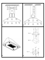
The appliance is already arranged both for filtering and
for suction performances.
* In its filtering version (Fig.1), the air and fumes vented
by the appliance are depured both by a grease filter and
by an active coal filter, and put again into circulation
through the side-grids of the chimney. For this version
an air deflector placed on the superior part of the pipe
and allowing air-recycling is necessary (Fig.1).
* In its sucking version (Fig.2), fumes are directly
conveyed outside, through an evacuation duct connected
with the superior part of the wall or the ceiling. Both coal
filter and air deflector are not necessary in this case.
* Before installing the appliance and in order not to
damage the appliance itself, the metal grease filter should
be removed. Such filter can be removed by pushing the
special filter handle toward the back side of the ranger
hood and turning it downwards so as to unfasten it from
its slot (Fig. 3).
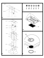
Attention: at least two people are needed to perform
the installation.
Before fixing the hood, place the electric feeding properly
into the ornamental pipe and place a hole for air
evacuation in case of a sucking version.
* Suction model
Place the upper plate (Fig. 4.1) on the ceiling. Drill 4
holes, 8 mm each, just next to the slots.
Insert the plastic dowels into the holes (Fig. 4.1-A) and
screw the plate on the ceiling (Fig. 4.1-B). Then fasten
the lower structure (Fig. 6.2) on the hood by making its
holes and the metric-thread screws welded on the fan
support coincide (Fig. 6.1). Insert the washers and nuts
provided (Fig. 6.2-A) and screw with an appropriate
tool.
Connect the drainpipe to the power unit nozzle and fix
securely with a hose clamp.
Insert the upper structure (Fig. 6.3) into the lowest one
and adjust its height as required by matching it with the
cooktop’s minimum height. Tighten the two structures
securely with the screws provided (Fig. 6.3-B).
INSTALLATION
When frying, please pay particular attention to fire
risk due to oil grease. Since it is highly inflammable,
fried oil is especially dangerous. Do not use uncovered
electric grills. In order to avoid possible fire risk, all
instructions for grease-filter cleaning and for removing
eventual grease deposits should be strictly followed.

6
Insert the two extension tubes (Fig. 6.4 & Fig. 6.5) from
above the two structures by making them come down
to the appropriate hood seat. Lift the hood together with
the structure and the extension tubes to make the four
springs (Fig. 6.6-E) hook to the slots (Fig. 6.3-C). Then
tighten the two elements securely (Fig. 5.1 & Fig. 5.2)
with the safety screws (Fig. 5.2-A) and connect the hood
tube to the drain hole. Make the electrical connections.
(For versions with display only) Lift the lower pipe until
the cable strap coming out of the sucking unit is
uncovered and connect it to the display cable strap. Put
down the lower pipe while paying attention it is being
properly introduced into the hood.
Lift the upper tube (Fig. 6.5) up to the ceiling and insert
the two self-tapping screws (Fig. 6.5-D).
*Filtering model
Place the upper plate (Fig. 4.1) on the ceiling. Drill 4 holes,
8 mm each, just next to the slots. Insert the plastic dowels
into the holes (Fig. 4.1-A). Fix the baffle (Fig. 4.2) to the
upper bracket (Fig. 4.3) with the four self-tapping screws
provided (Fig. 4.3A). Screw the plate together with the
baffle (Fig. 4.1B). Then fasten the lower structure (Fig. 6.2)
on the hood by making its holes and the metric-thread
screws welded on the fan support coincide (Fig. 6.1). Insert
the washers and nuts provided (Fig. 6.2-A) and screw with
an appropriate tool. Connect the drainpipe to the power
unit nozzle and fix securely with a hose clamp. Insert the
upper structure (Fig. 6.3) into the lowest one and adjust
its height as required by matching it with the cooktop’s
minimum height. Tighten the two structures securely with
the screws provided (Fig. 6.3-B). Insert the two extension
tubes (Fig. 6.4 & Fig. 6.5) from above the two structures
by making them come down to the appropriate hood seat.
Lift the hood together with the structure and the extension
tubes to make the four springs (Fig. 6.6-E) hook to the
slots (Fig. 6.3-C). Then tighten the two elements securely
(Fig. 5.1 & Fig. 5.2) with the safety screws (Fig. 5.2-A) and
connect the hood tube to the baffle’s lower hole.
Make the electrical connections. (For versions with display
only) Lift the lower pipe until the cable strap coming out
of the sucking unit is uncovered and connect it to the
display cable strap. Put down the lower pipe while paying
attention it is being properly introduced into the hood. Lift
the upper tube (Fig. 6.5) up to the ceiling and insert the
two self-tapping screws (Fig. 6.5-D).
Warning!
Before connecting the flexible exhausting pipe to the motor,
make sure the stop valve, which is on the air outlet of the
motor, can swing.
WORKING
Mod. 5CFB-36 IX luxury version (Fig. 7)
A: Light switch on/off
B: Motor switch on/off (1st rate level)
C: 2nd rate level switch
D: 3rd rate level switch
E: 4th rate level switch
MAINTENANCE
* An accurate maintenance guarantees good functioning
and long-lasting performance.
* Particular care is due to the grease filter panel. It can
be removed by pushing its special handle toward the
back-side of the range hood and turning the filter
downwards so as to unfasten it from its slot (Fig. 8).
To insert the filter just perform the opposite operation.
After 30 hours of operation, the push button control
panel will signal the saturation of the grease filter by
lighting all the buttons. Press the timer button to reset
. The grease filter should be cleaned by hand or in
dishwasher at least every two months or depending on
its use
* In case the appliance is used in its filtering version,
the active coal filter (Fig. 8Z) needs to be periodically
replaced. The coal filter can be removed by removing
the grease filter first (Fig. 8B), and by pulling its special
plastic tongue until it is unfastened from its slot. Re-
insert the coal filter by reversing the steps. The coal
filter needs replacing at least every six months depending
on the use.
* To clean the appliance itself tepid water and neutral
detergent are recommended, while abrasive products
should be avoided. For Steel appliances specialized
detergents are recommended (please follow the
instructions indicated o the product itself to obtain the
desired results).
* To replace the halogen lamps, remove first the glass-
blocking ring (Fig. 9A), by levering with a screw-driver
and thus removing the opaque glass (Fig. 9B) - when
performing this operation hold the opaque glass carefully.
Remove the lamp (Fig. 9C) without touching it with
uncovered hands. Replace it with another lamp of the
same kind. After the replacement, re-insert the glass-
blocking ring and fasten it.
Page is loading ...
Page is loading ...
Page is loading ...
Page is loading ...
Page is loading ...
Page is loading ...
Page is loading ...
Page is loading ...

FAGOR Stainless Steel Hoods
PRODUCT WARRANTY
ONE-YEAR LIMITED WARRANTY
For one year from the date of purchase, provided this product is operated and maintained in accordance with the instructions attached to or
furnished with the product, Fagor America Inc. will replace parts and provide labor to correct defects in materials or workmanship. Service
has to be provided by a Fagor America Inc. designated service company. Please contact Fagor America at 1 877 743 2467 or by email at
THIS LIMITED WARRANTY DOESN’T COVER:
1. Repairs when the product is used in other than normal, single family household use.
2. Damage resulting from accident, alteration, misuse, abuse, fire, acts of God, improper installation, installation not in accordance
with local electrical and plumbing codes, or use not approved by Fagor America.
3. Replacement parts or repair labor costs if the product is operated outside of the United States/Canada
4. Pick up/delivery. This product is designated to be repaired in the home.
FAGOR AMERICA WILL NOT BE LIABLE FOR INCIDENTAL OR CONSEQUENTIAL DAMAGES
Some states do not allow the exclusion or limitation of incidental or consequential damages so this exclusion or limitation may not apply to
you. This warranty gives you specific legal rights and you may also have other rights which vary from state to state.
IF YOU NEED SERVICE
Please contact Customer Care at Fagor America at 1 877 743 2467 or email Fagor America at [email protected]
WARRANTY REGISTRATION CARD Stainless Steel Hoods
Register your warranty on line at
www.fagoramerica.com
IMPORTANT NOTICE: PLEASE COMPLETE AND MAIL THIS WARRANTY REGISTRATION CARD IMMEDIATELY TO
PROTECT YOUR WARRANTY SERVICE
Mr./Mrs./Ms.: ____________________________________________________________________________________________________________
Address __________________________________________________________________________________________________________________
City __________________________________ State_________ Zip Code_____________________________________________________________
Phone: ______________________________________________ E-mail:_______________________________________________________________
Date of purchase: __________________________________________________________________________________________________________
Name of Dealer: ___________________________________________________________________________________________________________
Model number**: __________________________________________Serial Number**:_________________________________________________
Comments: _______________________________________________________________________________________________________________
__________________________________________________________________________________________________________________________
** The model and serial number are located on the left side of the coffee machine
Page is loading ...
Page is loading ...
Page is loading ...
Page is loading ...
Page is loading ...

FAGOR AMERICA, INC.
PO BOX 94
LYNDHURST, NJ 07071
Toll Free: 1.800.207.0806
Email: infoappliances@fagoramerica.com
www.fagoramerica.com
The manufacturer reserves the right to modify the items described in this manual.
Le producteur se réserve le droit de modifi er les articles décrits dans cette guide.
El fabricante se reserva el derecho de modifi car los productos descritos en este manual.
-
 1
1
-
 2
2
-
 3
3
-
 4
4
-
 5
5
-
 6
6
-
 7
7
-
 8
8
-
 9
9
-
 10
10
-
 11
11
-
 12
12
-
 13
13
-
 14
14
-
 15
15
-
 16
16
-
 17
17
-
 18
18
-
 19
19
-
 20
20
-
 21
21


Fagor 5CFB-36 IX User manual
- Category
- Cooker hoods
- Type
- User manual
- This manual is also suitable for
Ask a question and I''ll find the answer in the document
Finding information in a document is now easier with AI
in other languages
- français: Fagor 5CFB-36 IX Manuel utilisateur
- español: Fagor 5CFB-36 IX Manual de usuario