
ATtiny104 Xplained Nano
ATtiny104 Xplained Nano Evaluation Kit User's Guide
Preface
The Microchip ATtiny104 Xplained Nano Evaluation Kit is a hardware platform to evaluate the ATtiny104
microcontroller.
Supported by the Atmel Studio and MPLAB
®
X integrated development platform, the kit provides easy access to the
features of the Microchip ATtiny104 and explains how to integrate the device in a custom design.
The Xplained Nano MCU series evaluation kits include an on-board mini embedded programmer, and no external
tools are necessary to program the ATtiny104.
© 2019 Microchip Technology Inc.
User Guide
DS40002160A-page 1

Table of Contents
Preface........................................................................................................................................................... 1
1. Introduction............................................................................................................................................. 3
1.1. Features....................................................................................................................................... 3
1.2. Kit Overview................................................................................................................................. 3
2. Getting Started........................................................................................................................................ 4
2.1. Xplained Nano Quick Start........................................................................................................... 4
2.2. Design Documentation and Relevant Links................................................................................. 4
3. Xplained Nano.........................................................................................................................................6
3.1. Mini Embedded Debugger............................................................................................................6
3.2. Power Sources............................................................................................................................. 6
3.3. Xplained Nano Standard Pinout................................................................................................... 7
3.4. Disconnecting mEDBG.................................................................................................................8
4. Hardware User Guide............................................................................................................................. 9
4.1. Connectors...................................................................................................................................9
4.2. Current Measurement.................................................................................................................. 9
4.3. Peripherals................................................................................................................................. 10
5. Embedded Debugger Implementation...................................................................................................11
5.1. Tiny Program Interface............................................................................................................... 11
5.2. Virtual COM Port.........................................................................................................................11
6. Hardware Revision History and Known Issues..................................................................................... 12
6.1. Identifying Product ID and Revision........................................................................................... 12
6.2. Fuse Masking............................................................................................................................. 12
6.3. Revision 2...................................................................................................................................12
6.4. Revision 1...................................................................................................................................12
7. Document Revision History...................................................................................................................13
The Microchip Website.................................................................................................................................14
Product Change Notification Service............................................................................................................14
Customer Support........................................................................................................................................ 14
Microchip Devices Code Protection Feature................................................................................................ 14
Legal Notice................................................................................................................................................. 14
Trademarks.................................................................................................................................................. 15
Quality Management System....................................................................................................................... 15
Worldwide Sales and Service.......................................................................................................................16
ATtiny104 Xplained Nano
© 2019 Microchip Technology Inc.
User Guide
DS40002160A-page 2

1. Introduction
1.1 Features
• ATtiny104 Microcontroller
• One Yellow User LED
• One Mechanical Button
• mEDBG
– Auto-ID for board identification in Atmel Studio/Microchip MPLAB
®
X IDE
– One green board status LED
– Programming
– Virtual COM port (CDC)
• USB Powered
1.2 Kit Overview
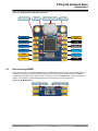
The Microchip ATtiny104 Xplained Nano Evaluation kit is a hardware platform to evaluate the ATtiny104.
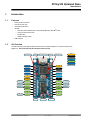
Figure 1-1. ATtiny104 Xplained Nano Evaluation Kit Overview
RESET
TPI DATA
TPI CLK
NC
VREG
VUSB
GND
CLK OUT
CDC T X
CDC RX
VCC
PA0
PA1
PA2
PA3
PA4
PA5
GND
PB3
PB2
PB1
PB0
PA7
PA6
Micro USB Connector
User LED User button
mEDB G
ATtiny104
Power disconnect mEDB G disconnectStatus LED
TPI CLK
TPI DATA
RESET
USER L ED
USER BTN
CDC TX
CDC RX
Power
Ground
Clock
Serial
Target I/O
Shared I/Os
Program/Debug
ATtiny104 Xplained Nano
Introduction
© 2019 Microchip Technology Inc.
User Guide
DS40002160A-page 3

2. Getting Started
2.1 Xplained Nano Quick Start
Steps to start exploring the Microchip Xplained Nano platform:
1. Download Atmel Studio/Microchip MPLAB
®
X IDE.
2. Launch Atmel Studio/Microchip MPLAB
®
X IDE.
3. Optional: Use Atmel START to generate drivers and examples.
4. Write your application code.
5. Connect a USB cable (Standard-A to Micro-B or Micro-AB) between the PC and the debug USB port on the
kit.
When the Xplained Nano kit is connected to your computer for the first time, the operating system will perform a
driver software installation. The driver file supports both 32- and 64-bit versions of Microsoft
®
Windows
®
XP,
Windows Vista
®
, Windows 7, Windows 8, and Windows 10. The drivers for the kit are included with Atmel Studio/
Microchip MPLAB
®
X IDE.
Once the Xplained Nano board is powered, the green status LED will blink and Atmel Studio/Microchip MPLAB
®
X
IDE will auto-detect which Xplained Nano board is connected. Atmel Studio/Microchip MPLAB
®
X IDE will present
relevant information like data sheets and kit documentation. The ATtiny104 device is programmed by the on-board
Mini Embedded Debugger and therefore, no external programmer tool is required.
2.2 Design Documentation and Relevant Links
The following list contains links to the most relevant documents and software for the ATtiny104 Xplained Nano.
• Xplained Products - Xplained Evaluation Kits are a series of easy-to-use evaluation kits for Microchip
microcontrollers and other Microchip products.
– Xplained Nano - used for low pin count devices and provides a minimalistic solution with access to all I/O
pins of the target microcontroller.
– Xplained Mini - used for medium pin count devices and adds Arduino Uno compatible header footprint and
a prototyping area.
– Xplained Pro - used for medium-to-high pin count devices that features advanced debugging and
standardized extensions for peripheral functions.
Note: All the above kits have on-board programmers/debuggers, which creates a set of low-cost boards for
evaluation and demonstration of features and capabilities of different Microchip products.
• Atmel Studio - Free IDE for the development of C/C++ and assembler code for microcontrollers.
• MPLAB
®
X IDE - MPLAB
®
X IDE is a software program that runs on a PC (Windows
®
, Mac OS
®
, Linux
®
) to
develop applications for Microchip microcontrollers and digital signal controllers. It is called an Integrated
Development Environment (IDE) because it provides a single integrated “environment” to develop code for
embedded microcontrollers.
• MPLAB
®
Code Configurator - MPLAB
®
Code Configurator (MCC) is a free software plug-in that provides a
graphical interface to configure peripherals and functions specific to your application.
• IAR Embedded Workbench
®
for AVR
®
- This is a commercial C/C++ compiler that is available for 8-bit AVR.
There is a 30-day evaluation version as well as a 4 KB code-size-limited kick-start version available from their
website.
• Atmel START - Atmel START is an online tool that helps the user to select and configure software components
and tailor your embedded application in a usable and optimized manner.
• Microchip Sample Store - Microchip sample store where you can order samples of devices.
• Data Visualizer - Data Visualizer is a program used for processing and visualizing data. The Data Visualizer
can receive data from various sources such as the EDBG Data Gateway Interface found on Curiosity Nano and
Xplained Pro boards and COM Ports.
ATtiny104 Xplained Nano
Getting Started
© 2019 Microchip Technology Inc.
User Guide
DS40002160A-page 4


3. Xplained Nano
Xplained Nano is an evaluation platform that provides a set of small boards with access to all microcontroller I/O’s.
The platform consists of a series of low pin count Microcontroller (MCU) boards, which are integrated with Atmel
Studio/Microchip MPLAB
®
X IDE to present relevant user guides, application notes, data sheets, and example code
through Atmel Studio/Microchip MPLAB
®
X IDE. The platform also features a Virtual COM port for serial
communication to a host PC.
3.1 Mini Embedded Debugger
The ATtiny104 Xplained Nano contains the Mini Embedded Debugger (mEDBG) for on-board programming. The
mEDBG is a composite USB device of two interfaces: a debugger and a virtual COM port.
Together with Atmel Studio, the mEDBG debugger interface can program the ATtiny104. On ATtiny104 Xplained
Nano, the TPI interface is connected between the mEDBG and the ATtiny104.
The virtual COM port is connected to a UART on the ATtiny104 and provides an easy way to communicate with the
target application through the terminal software. It offers variable baud rate, parity, and Stop bit settings.
Note: The settings on the ATtiny104 must match the settings given in the terminal software.
Info: The virtual COM port in the mEDBG requires the terminal software to set the Data Terminal Ready
(DTR) signal to enable the UART pins connected to the ATtiny104. If the DTR signal is not enabled the
UART pins on the mEDBG are kept in high-z (tri-state), rendering the COM port unusable. The DTR signal
is automatically set by some terminal software, but it may have to be manually enabled in the target
terminal.
The mEDBG controls one status LED on the ATtiny104 Xplained Nano. The table below shows how the LED is
controlled in different operation modes.
Table 3-1. mEDBG LED Control
Operation Mode Status LED
Power-up LED is briefly lit
Normal operation LED is not lit
Programming Activity indicator; the LED flashes when programming/
debugging with the mEDBG
3.1.1 Xplained Nano Clock Output
The mEDBG outputs its CPU clock to the CLK pin 8, as shown in 3.3 Xplained Nano Standard Pinout. The clock
output can be used to feed the target device with a more accurate clock if this is needed for the application.
3.2 Power Sources
The kit can be powered by different sources. By default the kit will have a 5V supply and the voltage is taken directly
from the USB port through a 500 mA PTC fuse. The voltage from the USB connector can vary between 4.4V to 5.25V
(according to USB spec).
If other voltages are required, the kit must be disconnected from the USB to avoid damage or contention to the USB
power. The mEDBG must also be disconnected from the target section of the board. The board can be powered by
applying a voltage to one of the power connections on the board, according to the table below. To avoid any power
leakage through the mEDBG, this should also be disconnected by removing the resistors shown in Figure 3-3. For
placement of power connections, see 3.3 Xplained Nano Standard Pinout.
ATtiny104 Xplained Nano
Xplained Nano
© 2019 Microchip Technology Inc.
User Guide
DS40002160A-page 6

Table 3-2. Power Connections
Power Connection Description
VUSB USB Voltage output when USB is connected (behind a PTC fuse). Can be used as power
input when USB is not used.
VREG Regulated voltage from VUSB. If the kit does not have a regulator, this is directly connected
to VUSB.
VCC Target voltage supply. By default, connected to VREG through a 0Ω resistor. Apply external
voltage here if the resistor is removed.
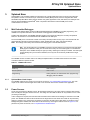
Figure 3-1. Power Supply Block Diagram
USB Target MCUPTC
Power source
Power connection
Power consumer
0-ohm Resistor
VUSB /
VREG
VCC
mEDBG
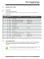
3.3 Xplained Nano Standard Pinout
Xplained Nano kits have a standard pinout in the mEDBG section, as shown in the tables and figure below. The
program/debug pins will change depending on the target interface but will remain at the same locations.
Xplained Nano kits have a target section where all I/O pins will be available and fanned out. Except for the VCC and
GND pins with fixed positions, there are no defined pin functions in this area. The first pin in the target area is the
VCC pin, located right next to the VREG pin of the standard section. The last pin is GND, and it is located next to the
CDC RX pin in the standard section. For reference, see the figure below.
3.3.1 Standard Pinout for TPI
Table 3-3. Xplained Nano Standard Pinout for TPI
Pin Number Name Description
1 RST Reset line
2 TPID TPI Program data line
3 TPIC TPI Program clock output
4 NC No Connect
5 VREG Regulated voltage or VUSB if no regulator present
6 UART RX mEDBG UART RX line
7 UART TX mEDBG UART TX line
8 CLK mEDBG clock output
9 GND Ground
10 VUSB USB voltage
ATtiny104 Xplained Nano
Xplained Nano
© 2019 Microchip Technology Inc.
User Guide
DS40002160A-page 7

Figure 3-2. Xplained Nano Standard Pinout for TPI
RESET
TPI DATA
TPI CLK
NC
VREG
VUSB
GND
CLK OUT
CDC TX
CDC RX
VCC GND
Micro USB ConnectormEDBGPower disconnect Status LED
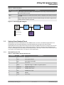
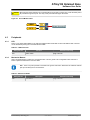
3.4 Disconnecting mEDBG
The target device can be completely separated from the mEDBG, but this requires some small modifications to the
board using a soldering iron. By removing the resistors in the sections shown in the figure below, the mEDBG is
completely disconnected from the target controller. If desired to connect the mEDBG again, solder in 0Ω resistors or
solder in 100-mil headers on the header footprints and use wire-straps to connect the interfaces.
Figure 3-3. Kit Modifications
Power disconnect mEDBG disconnect
ATtiny104 Xplained Nano
Xplained Nano
© 2019 Microchip Technology Inc.
User Guide
DS40002160A-page 8

4. Hardware User Guide
4.1 Connectors
4.1.1 ATtiny104 Xplained Nano Pinout
The ATtiny104 Xplained Nano has a direct fan-out of the I/O pins of the device and all I/O’s are accessible at the
edge connectors.
Table 4-1. Edge Connector
Edge
Connector
ATtiny104 Pin Functions Shared Functionality
1 V
CC
Power supply
2 PA[0] PCINT0/ADC0/AIN0/T0/CLKI/TPICLK mEDBG TPI Clock
3 PA[1] PCINT1/ADC1/AIN1/OC0B/TPIDATA mEDBG TPI Data
4 PA[2] PCINT2/RESET mEDBG Reset
5 PA[3] PCINT3/OC0A
6 PA[4] PCINT4/ICP0
7 PA[5] PCINT5/ADC2/OC0B User LED
8 PA[6] PCINT6/ADC3
9 PA[7] PCINT7
10 PB[0] PCINT8/ADC4
11 PB[1] PCINT9/INT0/ADC5/XCK0/OC0A/CLKO User button
12 PB[2] PCINT10/ADC6/TxD0/ICP0 mEDBG CDC RX
13 PB[3] PCINT11/ADC7/ACO/RxD0/T0 mEDBG CDC TX
14 GND Ground
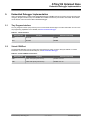
4.2 Current Measurement
The power to the target controller ATtiny104 is connected from the VREG supply to the targets VCC supply with a 0Ω
resistor, as shown in the figure below. To measure the power consumption of the device, remove the 0Ω resistor and
replace it with an ammeter. The ammeter can be connected between the VREG and VCC pads for easy
measurement.
Tip: To connect the two power domains again, solder in a 0Ω resistor on the footprint or a 100-mil header
on the header footprint at the edge of the board and place a jumper between VREG and VCC.
ATtiny104 Xplained Nano
Hardware User Guide
© 2019 Microchip Technology Inc.
User Guide
DS40002160A-page 9

CAUTION
Removing the resistor while the kit is powered without an ammeter or jumper may cause the ATtiny104 to
be powered through its I/O pins. This may cause permanent damage to the device.
Figure 4-1. Current Measurement
VREG
VCC
Power disconnect
4.3 Peripherals
4.3.1 LED
There is one yellow LED available on the ATtiny104 Xplained Nano board that can be turned ON and OFF. The LED
can be activated by driving the connected I/O line to GND.
Table 4-2. LED Connection
ATtiny104 Pin Function Shared Functionality
PA5 Yellow LED0 Edge connector
4.3.2 Mechanical Buttons
ATtiny104 Xplained Nano contains one mechanical button. This is a generic user configurable button and when a
button is pressed it will drive the I/O line to GND.
Info: There is no pull-up resistor connected to the generic user button. Remember to enable the internal
pull-up in the ATtiny104 to use the button.
Table 4-3. Mechanical Button
ATtiny104 Pin Description Shared Functionality
PB1 User button Edge connector
ATtiny104 Xplained Nano
Hardware User Guide
© 2019 Microchip Technology Inc.
User Guide
DS40002160A-page 10

5. Embedded Debugger Implementation
ATtiny104 Xplained Nano contains a Mini Embedded Debugger (mEDBG) that can be used to program the ATtiny104
using Tiny Program Interface (TPI). The mEDBG also includes a Virtual Com port interface over UART. Atmel Studio
can be used as a front end for the Mini Embedded Debugger.
5.1 Tiny Program Interface
The Tiny Program Interface (TPI) uses two pins to communicate with the target. For further information on how to use
the programming capabilities of the mEDBG, see Mini Embedded Debugger.
Table 5-1. TPI Connections
ATtiny104 Pin Function Shared Functionality
PA0 TPI clock mEDBG
PA1 TPI data mEDBG
5.2 Virtual COM Port
The Embedded Debugger acts as a Virtual Com Port gateway by using one of the ATtiny104 UARTs. For further
information on how to use the Virtual COM port, see Mini Embedded Debugger.
Table 5-2. Virtual COM Port Connections
ATtiny104 Pin Function Shared Functionality
PB2 UART TXD (ATtiny104 TX line) mEDBG CDC RX
PB3 UART RXD (ATtiny104 RX line) mEDBG CDC TX
ATtiny104 Xplained Nano
Embedded Debugger Implementation
© 2019 Microchip Technology Inc.
User Guide
DS40002160A-page 11

6. Hardware Revision History and Known Issues
This user guide provides the latest available revision of the kit. This section contains information about known issues,
a revision history of older revisions, and how older revisions differ from the latest revision.
6.1 Identifying Product ID and Revision
The revision and product identifier of Xplained Nano boards can be found in two ways; either through Atmel Studio/
Microchip MPLAB
®
X IDE or by looking at the sticker on the bottom side of the PCB.
By connecting an Xplained Nano board to a computer with Atmel Studio/Microchip MPLAB
®
X IDE running, an
information window will pop up. The first six digits of the serial number, which is listed under kit details, contain the
product identifier and revision.
The same information can be found on the sticker on the bottom side of the PCB. Most kits will print the identifier and
revision in plain text as A09-nnnn\rr, where nnnn is the identifier and rr is the revision. Boards with limited space have
a sticker with only a QR-code, which contains a serial number string.
The serial number string has the following format:
"nnnnrrssssssssss"
n = product identifier
r = revision
s = serial number
The product identifier for ATtiny104 Xplained Nano is A09-2678.
6.2 Fuse Masking
The ATtiny104 RSTDISBL(External Reset disable) fuse has been masked out in the mEDBG firmware. This is done
to avoid users disabling programming and debugging of the ATtiny104.
6.3 Revision 2
The target device U200 on revision 2 of the kit has been changed from engineering samples (ATTINY104-SSNRES)
to non-engineering samples (ATTINY104-SSNR).
6.4 Revision 1
Revision 1 is the initially released revision.
Engineering samples are mounted on revision 1 for the target device U200 (ATTINY104-SSNRES).
ATtiny104 Xplained Nano
Hardware Revision History and Known Issues
© 2019 Microchip Technology Inc.
User Guide
DS40002160A-page 12

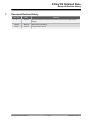
7. Document Revision History
Doc. Rev. Date Comment
A 12/2019 Microchip DS40002160 replaces Atmel 42671; Added section regarding fuse
masking.
42671B 08/2016 Add revision 2 information.
42671A 02/2016 Initial document release.
ATtiny104 Xplained Nano
Document Revision History
© 2019 Microchip Technology Inc.
User Guide
DS40002160A-page 13

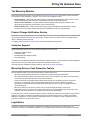
The Microchip Website
Microchip provides online support via our website at http://www.microchip.com/. This website is used to make files
and information easily available to customers. Some of the content available includes:
• Product Support – Data sheets and errata, application notes and sample programs, design resources, user’s
guides and hardware support documents, latest software releases and archived software
• General Technical Support – Frequently Asked Questions (FAQs), technical support requests, online
discussion groups, Microchip design partner program member listing
• Business of Microchip – Product selector and ordering guides, latest Microchip press releases, listing of
seminars and events, listings of Microchip sales offices, distributors and factory representatives
Product Change Notification Service
Microchip’s product change notification service helps keep customers current on Microchip products. Subscribers will
receive email notification whenever there are changes, updates, revisions or errata related to a specified product
family or development tool of interest.
To register, go to http://www.microchip.com/pcn and follow the registration instructions.
Customer Support
Users of Microchip products can receive assistance through several channels:
• Distributor or Representative
• Local Sales Office
• Embedded Solutions Engineer (ESE)
• Technical Support
Customers should contact their distributor, representative or ESE for support. Local sales offices are also available to
help customers. A listing of sales offices and locations is included in this document.
Technical support is available through the website at: http://www.microchip.com/support
Microchip Devices Code Protection Feature
Note the following details of the code protection feature on Microchip devices:
• Microchip products meet the specification contained in their particular Microchip Data Sheet.
• Microchip believes that its family of products is one of the most secure families of its kind on the market today,
when used in the intended manner and under normal conditions.
• There are dishonest and possibly illegal methods used to breach the code protection feature. All of these
methods, to our knowledge, require using the Microchip products in a manner outside the operating
specifications contained in Microchip’s Data Sheets. Most likely, the person doing so is engaged in theft of
intellectual property.
• Microchip is willing to work with the customer who is concerned about the integrity of their code.
• Neither Microchip nor any other semiconductor manufacturer can guarantee the security of their code. Code
protection does not mean that we are guaranteeing the product as “unbreakable.”
Code protection is constantly evolving. We at Microchip are committed to continuously improving the code protection
features of our products. Attempts to break Microchip’s code protection feature may be a violation of the Digital
Millennium Copyright Act. If such acts allow unauthorized access to your software or other copyrighted work, you
may have a right to sue for relief under that Act.
Legal Notice
Information contained in this publication regarding device applications and the like is provided only for your
convenience and may be superseded by updates. It is your responsibility to ensure that your application meets with
ATtiny104 Xplained Nano
© 2019 Microchip Technology Inc.
User Guide
DS40002160A-page 14

your specifications. MICROCHIP MAKES NO REPRESENTATIONS OR WARRANTIES OF ANY KIND WHETHER
EXPRESS OR IMPLIED, WRITTEN OR ORAL, STATUTORY OR OTHERWISE, RELATED TO THE INFORMATION,
INCLUDING BUT NOT LIMITED TO ITS CONDITION, QUALITY, PERFORMANCE, MERCHANTABILITY OR
FITNESS FOR PURPOSE. Microchip disclaims all liability arising from this information and its use. Use of Microchip
devices in life support and/or safety applications is entirely at the buyer’s risk, and the buyer agrees to defend,
indemnify and hold harmless Microchip from any and all damages, claims, suits, or expenses resulting from such
use. No licenses are conveyed, implicitly or otherwise, under any Microchip intellectual property rights unless
otherwise stated.
Trademarks
The Microchip name and logo, the Microchip logo, Adaptec, AnyRate, AVR, AVR logo, AVR Freaks, BesTime,
BitCloud, chipKIT, chipKIT logo, CryptoMemory, CryptoRF, dsPIC, FlashFlex, flexPWR, HELDO, IGLOO, JukeBlox,
KeeLoq, Kleer, LANCheck, LinkMD, maXStylus, maXTouch, MediaLB, megaAVR, Microsemi, Microsemi logo, MOST,
MOST logo, MPLAB, OptoLyzer, PackeTime, PIC, picoPower, PICSTART, PIC32 logo, PolarFire, Prochip Designer,
QTouch, SAM-BA, SenGenuity, SpyNIC, SST, SST Logo, SuperFlash, Symmetricom, SyncServer, Tachyon,
TempTrackr, TimeSource, tinyAVR, UNI/O, Vectron, and XMEGA are registered trademarks of Microchip Technology
Incorporated in the U.S.A. and other countries.
APT, ClockWorks, The Embedded Control Solutions Company, EtherSynch, FlashTec, Hyper Speed Control,
HyperLight Load, IntelliMOS, Libero, motorBench, mTouch, Powermite 3, Precision Edge, ProASIC, ProASIC Plus,
ProASIC Plus logo, Quiet-Wire, SmartFusion, SyncWorld, Temux, TimeCesium, TimeHub, TimePictra, TimeProvider,
Vite, WinPath, and ZL are registered trademarks of Microchip Technology Incorporated in the U.S.A.
Adjacent Key Suppression, AKS, Analog-for-the-Digital Age, Any Capacitor, AnyIn, AnyOut, BlueSky, BodyCom,
CodeGuard, CryptoAuthentication, CryptoAutomotive, CryptoCompanion, CryptoController, dsPICDEM,
dsPICDEM.net, Dynamic Average Matching, DAM, ECAN, EtherGREEN, In-Circuit Serial Programming, ICSP,
INICnet, Inter-Chip Connectivity, JitterBlocker, KleerNet, KleerNet logo, memBrain, Mindi, MiWi, MPASM, MPF,
MPLAB Certified logo, MPLIB, MPLINK, MultiTRAK, NetDetach, Omniscient Code Generation, PICDEM,
PICDEM.net, PICkit, PICtail, PowerSmart, PureSilicon, QMatrix, REAL ICE, Ripple Blocker, SAM-ICE, Serial Quad
I/O, SMART-I.S., SQI, SuperSwitcher, SuperSwitcher II, Total Endurance, TSHARC, USBCheck, VariSense,
ViewSpan, WiperLock, Wireless DNA, and ZENA are trademarks of Microchip Technology Incorporated in the U.S.A.
and other countries.
SQTP is a service mark of Microchip Technology Incorporated in the U.S.A.
The Adaptec logo, Frequency on Demand, Silicon Storage Technology, and Symmcom are registered trademarks of
Microchip Technology Inc. in other countries.
GestIC is a registered trademark of Microchip Technology Germany II GmbH & Co. KG, a subsidiary of Microchip
Technology Inc., in other countries.
All other trademarks mentioned herein are property of their respective companies.
©
2019, Microchip Technology Incorporated, Printed in the U.S.A., All Rights Reserved.
ISBN: 978-1-5224-5364-2
Quality Management System
For information regarding Microchip’s Quality Management Systems, please visit http://www.microchip.com/quality.
ATtiny104 Xplained Nano
© 2019 Microchip Technology Inc.
User Guide
DS40002160A-page 15

AMERICAS ASIA/PACIFIC ASIA/PACIFIC EUROPE
Corporate Office
2355 West Chandler Blvd.
Chandler, AZ 85224-6199
Tel: 480-792-7200
Fax: 480-792-7277
Technical Support:
http://www.microchip.com/support
Web Address:
http://www.microchip.com
Atlanta
Duluth, GA
Tel: 678-957-9614
Fax: 678-957-1455
Austin, TX
Tel: 512-257-3370
Boston
Westborough, MA
Tel: 774-760-0087
Fax: 774-760-0088
Chicago
Itasca, IL
Tel: 630-285-0071
Fax: 630-285-0075
Dallas
Addison, TX
Tel: 972-818-7423
Fax: 972-818-2924
Detroit
Novi, MI
Tel: 248-848-4000
Houston, TX
Tel: 281-894-5983
Indianapolis
Noblesville, IN
Tel: 317-773-8323
Fax: 317-773-5453
Tel: 317-536-2380
Los Angeles
Mission Viejo, CA
Tel: 949-462-9523
Fax: 949-462-9608
Tel: 951-273-7800
Raleigh, NC
Tel: 919-844-7510
New York, NY
Tel: 631-435-6000
San Jose, CA
Tel: 408-735-9110
Tel: 408-436-4270
Canada - Toronto
Tel: 905-695-1980
Fax: 905-695-2078
Australia - Sydney
Tel: 61-2-9868-6733
China - Beijing
Tel: 86-10-8569-7000
China - Chengdu
Tel: 86-28-8665-5511
China - Chongqing
Tel: 86-23-8980-9588
China - Dongguan
Tel: 86-769-8702-9880
China - Guangzhou
Tel: 86-20-8755-8029
China - Hangzhou
Tel: 86-571-8792-8115
China - Hong Kong SAR
Tel: 852-2943-5100
China - Nanjing
Tel: 86-25-8473-2460
China - Qingdao
Tel: 86-532-8502-7355
China - Shanghai
Tel: 86-21-3326-8000
China - Shenyang
Tel: 86-24-2334-2829
China - Shenzhen
Tel: 86-755-8864-2200
China - Suzhou
Tel: 86-186-6233-1526
China - Wuhan
Tel: 86-27-5980-5300
China - Xian
Tel: 86-29-8833-7252
China - Xiamen
Tel: 86-592-2388138
China - Zhuhai
Tel: 86-756-3210040
India - Bangalore
Tel: 91-80-3090-4444
India - New Delhi
Tel: 91-11-4160-8631
India - Pune
Tel: 91-20-4121-0141
Japan - Osaka
Tel: 81-6-6152-7160
Japan - Tokyo
Tel: 81-3-6880- 3770
Korea - Daegu
Tel: 82-53-744-4301
Korea - Seoul
Tel: 82-2-554-7200
Malaysia - Kuala Lumpur
Tel: 60-3-7651-7906
Malaysia - Penang
Tel: 60-4-227-8870
Philippines - Manila
Tel: 63-2-634-9065
Singapore
Tel: 65-6334-8870
Taiwan - Hsin Chu
Tel: 886-3-577-8366
Taiwan - Kaohsiung
Tel: 886-7-213-7830
Taiwan - Taipei
Tel: 886-2-2508-8600
Thailand - Bangkok
Tel: 66-2-694-1351
Vietnam - Ho Chi Minh
Tel: 84-28-5448-2100
Austria - Wels
Tel: 43-7242-2244-39
Fax: 43-7242-2244-393
Denmark - Copenhagen
Tel: 45-4450-2828
Fax: 45-4485-2829
Finland - Espoo
Tel: 358-9-4520-820
France - Paris
Tel: 33-1-69-53-63-20
Fax: 33-1-69-30-90-79
Germany - Garching
Tel: 49-8931-9700
Germany - Haan
Tel: 49-2129-3766400
Germany - Heilbronn
Tel: 49-7131-72400
Germany - Karlsruhe
Tel: 49-721-625370
Germany - Munich
Tel: 49-89-627-144-0
Fax: 49-89-627-144-44
Germany - Rosenheim
Tel: 49-8031-354-560
Israel - Ra’anana
Tel: 972-9-744-7705
Italy - Milan
Tel: 39-0331-742611
Fax: 39-0331-466781
Italy - Padova
Tel: 39-049-7625286
Netherlands - Drunen
Tel: 31-416-690399
Fax: 31-416-690340
Norway - Trondheim
Tel: 47-72884388
Poland - Warsaw
Tel: 48-22-3325737
Romania - Bucharest
Tel: 40-21-407-87-50
Spain - Madrid
Tel: 34-91-708-08-90
Fax: 34-91-708-08-91
Sweden - Gothenberg
Tel: 46-31-704-60-40
Sweden - Stockholm
Tel: 46-8-5090-4654
UK - Wokingham
Tel: 44-118-921-5800
Fax: 44-118-921-5820
Worldwide Sales and Service
© 2019 Microchip Technology Inc.
User Guide
DS40002160A-page 16
-
 1
1
-
 2
2
-
 3
3
-
 4
4
-
 5
5
-
 6
6
-
 7
7
-
 8
8
-
 9
9
-
 10
10
-
 11
11
-
 12
12
-
 13
13
-
 14
14
-
 15
15
-
 16
16


Microchip Technology ATtiny104 Xplained Nano User manual
- Type
- User manual
- This manual is also suitable for
Ask a question and I''ll find the answer in the document
Finding information in a document is now easier with AI
Related papers
-
Microchip Technology AT42QT1010 User manual
-
-
-
-
-
-
-
-
-
Other documents
-
MICROCHIP ATWINC3400-XSTK Operating instructions
-
-
-
Atmel SAM4L Xplained Pro Quick start guide
-
-
-
-
-
-