
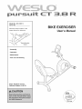
Model No. 831.21811.1
Serial No.
Write the serial number in the
space above for reference.
Serial Number
Decal
• Assembly
• Operation
• Maintenance
• Part List and Drawing
Sears, Roebuck and Co.
Hoffman Estates, IL 60179
I
EXERCISE
User's Manual

TABLE OF CONTENTS
WARNING DECAL PLACEMENT .............................................................. 2
IMPORTANT PRECAUTIONS ................................................................ 3
BEFORE YOU BEGIN ...................................................................... 4
ASSEMBLY ............................................................................... 5
HOW TO USE THE EXERCISE BIKE ......................................................... 11
MAINTENANCE AND TROUBLESHOOTING ................................................... 14
FCC INFORMATION ....................................................................... 15
EXERCISE GUIDELINES ................................................................... 16
PART LIST .............................................................................. 18
EXPLODED DRAWING .................................................................... 19
ORDERING REPLACEMENT PARTS .................................................. Back Cover
90 DAY FULL WARRANTY .......................................................... Back Cover
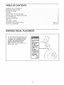
WARNING DECAL PLACEMENT
This drawing shows the location(s) of the
warning decal(s). If a decal is missing
or illegible, call 1-866-699-3756 and
request a free replacement decal.
Apply the decal in the location
shown. Note: The decal(s) may not be
shown at actual size.
• Misuseof this machine
may result in serious
injury.
• Read user's manual
prior to use and follow
all warnings and
instructions.
• Do not allow children
on or around machine.
• Pedals continue to
spin when you stop
pedaling.
• Spinning pedals can
cause injury.
• Reduce pedal speed
in acontrolled manner.
• User weight must not
exceed 250 pounds.
, Replace label if
damaged, illegible, or
removed. _
2

iMPORTANT PRECAUTIONS
WARNING: Toreducetheriskofse.ousinjury,reada. mportantprecautions and
instructions in this manual and all warnings on your exercise bike before using your exercise bike.
iCON assumes no responsibility for personal injury or property damage sustained by or through the
use of this product.
1. Before beginning any exercise program, 9.
consult your physician. This is especially
important for persons over age 35 or per-
sons with pre-existing health problems.
.
.
=
Use the exercise bike only as described in
this manual.
it is the responsibility of the owner to ensure
that all users of the exercise bike are ade-
quately informed of all precautions.
The exercise bike is intended for home use
only. Do not use the exercise bike in a com-
mercial, rental, or institutiona! setting.
10.
11.
The exercise bike should not be used by
persons weighing more than 250 Ibs.
(113 kg).
Wear appropriate clothes while exercising;
do not wear loose clothes that could become
caught on the exercise bike. Always wear
athletic shoes for foot protection.
The pulse sensor is not a medical device.
Various factors, including the user's move=
ment, may affect the accuracy of heart rate
readings. The pulse sensor is intended only
as an exercise aid in determining heart rate
trends in general.
.
Keep the exercise bike indoors, away from
moisture and dust. Do not put the exercise
bike in a garage or covered patio, or near
water.
12.
The exercise bike does not have a free
wheel; the pedals will continue to move until
the flywheel stops. Reduce your pedaling
speed in a controlled way.
.
.
Place the exercise bike on a level surface
with at least 2 ft. (0.6 m) of clearance around
the exercise bike. To protect the floor or
carpet from damage, place a mat under the
exercise bike.
inspect and properly tighten all parts regular-
ly. Replace any worn parts immediately.
13.
14.
Always keep your back straight while using
the exercise bike; do not arch your back.
Over exercising may result in serious injury
or death, if you feel faint or if you experience
pain while exercising, stop immediately and
cool down.
8. Keep children under age 12 and pets away
from the exercise bike at all times.
3

BEFORE YOU BEGIN
Thank you for selecting the new WESLO ®PURSUIT
CT 3.8 R exercise bike. Cycling is an effective exer-
cise for increasing cardiovascular fitness, building
endurance, and toning the body. The PURSUIT CT
3.8 R exercise bike provides a selection of features
designed to make your workouts at home more effec-
tive and enjoyable.
For your benefit, read this manual carefully before
you use the exercise bike. If you have questions
after reading this manual, please see the back cover
of this manual. To help us assist you, note the product
model number and serial number before contacting
us. The model number and the location of the serial
number decal are shown on the front cover of this
manual.
Before reading further, please review the drawing
below and familiarize yourself with the labeled parts.
Handlebar
Console
Thumb Pulse Sensor
Resistance Knob
Seat
Seat Frame
Pedal/Strap
Adjustment Knob
Seat Handle
4

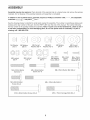
ASSEMBLY
Assembly requires two persons. Place all parts of the exercise bike in a cleared area and remove the packing
materials. Do not dispose of the packing materials until assembly is completed.
in addition to the included tool(s), assembly requires a Phillips screwdriver _, two adjustable
wrenches _, and pliers _.
See the drawings below to identify the small parts needed for assembly. The number in parentheses below each
drawing is the key number of the part, from the PART LIST near the end of this manual. The number following
the key number is the quantity needed for assembly. Note: If a part is not in the hardware kit, check to see if
it has been preassembled. To avoid damaging parts, do not use power tools for assembly. If a part is
missing, call 1-866-699-3756.
U
M4 Washer M6 Washer M6 Curved M8 Split M8 Curved
(70)-2 (68)-8 Washer (69)-4 Washer (42)-3 Washer (46)-2
M8 Washer
(54)-4
M8 Locknut
(10)-4
M10 Locknut
(65)-2
M4 x 5mm M4 x 8mm M4 x 15mm
M6 Locknut Self-tapping Screw Self-tapping
(63)-4 Screw (66)-2 (29)-2 Screw (47)-4
M6 x 30mm Button
Bolt (64)-4
M6 x 35mm Button
Screw (61)-8
M8 x 65mm Button Bolt (36)-2
M8 x 20mm Button
Screw (34)-3
M10 x 65mm Button Screw (33)-2
M8 x 125mm Bolt (62)-2
M10 x 75mm Carriage Bolt (30)-2
5

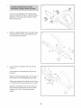
Turn the Front Stabilizer (2) so that the large
holes are facing the Frame (1). Attach the Front
Stabilizer to the Frame with two M10 x 65mm
Button Screws (33).
33
Large
Holes
.
Attach the Rear Stabilizer (6) to the Seat Frame
(5) with two M10 x 75mm Carriage Bolts (30)
and two M10 Locknuts (65).
65
30
.
Insert the end of the Seat Frame (5) into the
Frame (1).
Firmly press the Frame Bushing (56) into the
Frame (1).
Attach the Frame Bushing (56) to the Frame (1)
with two M4 x 5mm Self-tapping Screws (66).
Tighten the Adjustment Knob (9) into the Frame
(1). Carefully tip the exercise bike onto its side.
Attach the two Bumpers (57) to the Frame (1)
with two M4 x 8mm Screws (29) and two M4
Washers (70). Then, tip the exercise bike
upright.
29
56
5
6

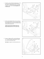
.
Attach the Left and Right Seat Brackets (14, 15)
to the Seat Frame (5) with two M8 x 125mm
Bolts (62), four M8 Washers (54), and two M8
Locknuts (10) as shown. Do not tighten the
Locknuts yet.
54
10
54 10
15
.
Attach a Seat Handle (59) to the round tube on
the Left Seat Bracket (14) with two M6 x 30mm
Button Bolts (64), two M6 Curved Washers (69),
and two M6 Locknuts (63).
Attach the other Seat Handle (59) to the
Right Seat Bracket (15) in the same way.
59
59
.
Attach the Backrest (60) to the Seat Brackets
(14, 15) with four M6 x 35mm Button Screws
(61) and four M6 Washers (68).
See step 4. Tighten the two M8 Locknuts (10).
60
68
15
68
61
68
61
7

7. 7
Attach the Seat (12) to the Seat Brackets (14,
15) with four M6 x 35mm Button Screws (61)
and four M6 Washers (68).
.
While another person holds the Upright (13) in
the position shown, connect the Extension Wire
(52) to the Reed Switch Wire (43).
Connect the Resistance Cable (19) to the
Lower Cable (45) in the following way:
oSee drawing A. Pull upward on the metal
bracket on the Lower Cable (45), and insert
the tip of the Resistance Cable (19) into the
wire clip inside the metal bracket as shown.
oSee drawing B. Firmly pull the Resistance
Cable (19) upward and slide it into the top of
the metal bracket as shown.
oSee drawing C. Using pliers, squeeze the
prongs on the upper end of the metal bracket
together.
Push the excess wire and cable downward into
the Frame (1), and insert the Upright (13) into
the Frame.
Tip: Avoid pinching the wires and cables.
Attach the Upright (13) to the Frame (1) with
three M8 x 20mm Button Screws (34) and three
M8 Split Washers (42).
8
Avoid pinching the _'_
wiresandcables
._ Metal
19_ ____i_cket
B
c
Meta i
Bracket
8

9. 9
Attach the Handlebar (53) to the Upright (13)
with two M8 x 65mm Button Bolts (36), two M8
Curved Washers (46), and two M8 Locknuts
(10).
13
53
36
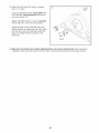
10. The Console (16) requires four AA batteries (not
included); alkaline batteries are recommended.
iMPORTANT: If the Console has been
exposed to cold temperatures, allow it to
warm to room temperature before inserting
batteries. Otherwise, you may damage the
console displays or other electronic compo-
nents. Remove the screw, remove the battery
cover, and insert the batteries into the battery
compartment. Make sure to orient the batter-
ies as shown by the diagram inside the bat-
tery compartment. Then, reattach the battery
cover.
10
Screw-,_ Battery Cover
' Batteries
i
i I
16
\
11. While another person holds the Console (16)
near the Upright (13), connect the console wire
to the Extension Wire (52).
Insert the wires downward into the Upright (13).
Tip: Avoid pinching the wires. Attach the
Console (16) to the Upright (13) with four M4 x
15mm Self-tapping Screws (47).
11
Avoid pinching
the wires
47
52
Console
Wire
9

12. Identify the Left Pedal (24), which is marked
with an "L" sticker.
Using an adjustable wrench, firmly tighten the
Left Pedal (24) counterclockwise into the left
arm of the Crank (21).
Tighten the Right Pedal (not shown) clockwise
into the right arm of the Crank (not shown).
Adjust the strap on the Left Pedal (24) to the
desired position, and press the end of the strap
onto the tab on the Left Pedal (24), Adjust the
strap on the Right Pedal (not shown) in the
same way.
12
Strap
13. Make sure that all parts are properly tightened before you use the exercise bike. After assembly is
completed, some extra parts may be left over. Place a mat under the exercise bike to protect the floor.
10

HOW TO USE THE EXERCISE BiKE
HOW TO ADJUST THE SEAT FRAME
For effective exercise, the seat should be in the proper
position. As you pedal, there should be a slight bend
in your knees when the pedals are in the most forward
position.
Frame
To adjust the seat frame, first loosen the adjustment
knob on the frame. Slide the seat frame forward or
backward to the desired position. Then, retighten the
adjustment knob.
HOW TO ADJUST THE PEDALING RESISTANCE
To increase the
resistance of the
pedals, turn the
resistance knob
clockwise; to
decrease the resis-
tance, turn the knob
counterclockwise.
IMPORTANT: Stop
turning the knob
when turning
becomes difficult,
or damage may
result.
/
Resistance
FEATURES OF THE CONSOLE
SCAN PULSE CALORIES
Pace RP_ SPEED TIME DISTANCE
Guide_
_'*" GO FASTER _ GO SLOWER
On/Reset
Display
Button
DISPLAY
I 2
Pace Workout
Button
Thumb Pulse Sensor
The console offers a selection of features designed to
make your workouts more effective. As you pedal, the
console will provide continuous exercise feedback.
You can even measure your heart rate using the built-
in thumb pulse sensor.
The console also offers two pace workouts that
prompt you to vary your pedaling pace while guiding
you through an effective workout.
To use the manual mode, see page 12. To use a
pace workout, see page 13.
Before using the console, make sure that batteries are
installed (see assembly step 10 on page 9). If there is
a sheet of clear plastic on the display, remove the
plastic.
11

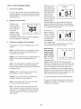
HOW TO USE THE MANUAL MODE
1. Turn on the console.
To turn on the console, press the On/Reset button
or begin pedaling. The entire display and the pace
guide will light for a moment; the console will then
be ready for use.
2. Select the manual mode.
When you turn
on the console,
the manual mode
will be selected.
If you have
selected a pace
workout, reselect
the manual mode
SCAN PULSE CALORIES
t!!,t'i!
M'MM
RPM SPEED TIME DISTANCE
by pressing the Pace Workout button repeatedly
until zeros appear in the display.
3. Follow your progress with the display.
The display can show the following workout infor-
mation:
RPM=The RPM meter on the left side of the dis-
play indicates your approximate pedaling pace
(revolutions per minute).
Speed=This mode shows your pedaling speed, in
miles per hour (mph) or kilometers per hour
(km/h).
Time--This mode shows the elapsed time. Note:
When a pace workout is selected, the display
shows the time remaining in the workout instead of
the elapsed time.
Distance=This mode shows the distance you
have pedaled, in miles or kilometers.
Calories=This mode shows the approximate
number of calories you have burned.
Pulse=This mode shows your heart rate when
you use the thumb pulse sensor.
Scan=This mode shows the speed, time, dis-
tance, calories, and pulse modes, for a few sec-
onds each, in a repeating cycle. Note: The pulse
mode will appear only when you are using the
pulse sensor.
When you turn on
the console, the Indicators
scan mode will be PULSECALORIES
selected automat-
2eically. One indica-
tor will appear ,,_
below the word
Scan to show that RRMSPEEDTIME DISTANCE
the scan mode is
selected, and a
second indicator will show which information is
currently displayed. Note: If you have selected a
different mode, press the Display button repeated-
ly to reselect the Scan mode.
To select the
speed, time, dis- SCANPULSECALORIES
tance, or calories dl
!
mode for continu-
U
d
ous display, press
the Display but- RP_SPEEDTIME DISTANCE
ton repeatedly.
The indicators will
show which mode is selected. Make sure there is
not an indicator below the word Scan.
Note: The con-
sole can show CALORIES
speed and dis-
tance in either
miles or kilome-
ters. The letters D=STANCE
"mph" or "km/h"
will appear in the
display to show which unit of measurement is
selected. To change the unit of measurement, first
hold down the On/Reset button for a few seconds.
An "E" (for English) or an "M" (for metric) will
appear in the display. Press the Display button to
change the unit of measurement. Note: When the
batteries are replaced, it may be necessary to res-
elect the desired unit of measurement.
SCAN PULSE
E
RPM SPEED TIME
To reset the display, press the On/Reset button.
To pause the console, stop pedaling. If the time is
displayed, it will flash. To continue your workout,
simply resume pedaling.
12

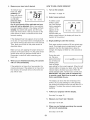
4. Measure your heart rate if desired. HOW TO USE A PACE WORKOUT
.
To measure your
heart rate, stop
pedaling and
place your thumb
on the pulse sen-
sor. Do not
press too hard,
or the circula-
SCAN PULSE CALORIES
rt
RPM SPEED TIME DISTANCE
tion in your thumb will be restricted and your
pulse will not be detected. After a few seconds,
the heart-shaped indicator in the display will flash
steadily, two dashes will appear, and then your
heart rate will be shown. Hold your thumb on the
pulse sensor for about 15 seconds for the most
accurate reading.
If the displayed heart rate appears to be too high
or too low, or if your heart rate is not displayed, lift
your thumb off the pulse sensor for a few seconds.
Then, place your thumb on the pulse sensor as
described above.
Make sure you are applying the proper amount of
pressure to the pulse sensor. Try the pulse sensor
several times until you become familiar with it.
Remember to stand still while measuring your
heart rate.
When you are finished exercising, the console
will turn off automatically.
If the pedals do not move for a few seconds, the
console will pause. If the pedals do not move for a
few minutes, the console will turn off and the dis-
play will be reset.
1. Turn on the console.
See step 1 on page 12.
2. Select a pace workout.
To select a pace
workout, press
the Pace Workout
button repeatedly
until P1 or P2
appears in the
display. A few
seconds after you
SCAN PULSE
P;
RPM SPEED TIME
CALORIES
DISTANCE
select a pace workout, the display will show the
duration of the workout.
3. Begin pedaling to start the workout.
Each pace workout consists of 30 one-minute seg-
ments. One target pace is programmed for each
segment. Any time the target pace is about to
change, the display will flash for a few seconds to
alert you.
During the work-
out, the pace
guide will prompt GoFASTER _ GOSLOWER
yOUto keep your
pedaling pace
near the target
pace setting for the current segment. When the left
indicator lights, increase your pace; when the right
indicator lights, decrease your pace. When the
center indicator lights, maintain your current pace.
iMPORTANT: The pace guide is intended only
to provide a goal. Make sure to pedal at a pace
that is comfortable for you.
The display can show the time remaining in the
workout. If you stop pedaling for a few seconds,
the workout will pause and the time will flash if it is
displayed. To restart the workout, simply resume
pedaling.
4. Follow your progress with the display.
See step 3 on page 12.
5. Measure your heart rate if desired.
See step 4 at the left.
6. When you are finished exercising, the console
will turn off automatically.
See step 5 at the left.
13

MAINTENANCE AND TROUBLESHOOTING
Inspect and tighten all parts of the exercise bike regu-
larly. Replace any worn parts immediately.
To clean the exercise bike, use a damp cloth and a
small amount of mild detergent. IMPORTANT: To
avoid damage to the console, keep liquids away
from the console and keep the console out of
direct sunlight.
BATTERY REPLACEMENT
If the console display becomes dim, replace all the
batteries at the same time; most console problems are
the result of low batteries. To replace the batteries,
see assembly step 10 on page 9.
HOW TO ADJUST THE REED SWITCH
If the console does not display correct feedback, the
reed switch should be adjusted. To adjust the reed
switch, you must first remove the left pedal and the
left shield. Using an adjustable wrench, turn the left
pedal clockwise and remove it. Next, remove all the
screws from the left and right shields; there are two
sizes of screws in the shields-note which size of
screw you remove from each hole. Then, gently pull
the left shield away from the frame.
Locate the Reed Switch (43). Turn the Crank (21) until
the Magnet (38) is aligned with the Reed Switch.
Loosen, but do not remove, the M4 x 15mm Self-tap-
ping Screw (47). Slide the Reed Switch slightly closer
to or away from the Magnet, and then retighten the
Screw. Turn the Crank for a moment. Repeat until the
console displays correct feedback. When the Reed
Switch is correctly adjusted, reattach the left shield
and the left pedal.
HOW TO ADJUST THE DRIVE BELT
If you can feel the pedals slip while you are pedaling,
even when the resistance is at the highest level, the
drive belt may need to be adjusted.
To adjust the drive belt, you must first remove the right
pedal and the right shield. Using an adjustable
wrench, turn the right pedal counterclockwise and
remove it. Next, remove all the screws from the left
and right shields; there are two sizes of screws in
the shields-note which size of screw you remove
from each hole. Then, gently pull the right shield
away from the frame.
Loosen the Flywheel Axle (39). Next, tighten the M6
Locknuts (63), one on each side of the Flywheel (37),
until the Drive Belt (35) is tight. Then, tighten the
Flywheel Axle and reattach the right shield and the
right pedal.
14

FCC iNFORMATiON
This equipment has been tested and found to comply with the limits for a Class B digital device, pursuant to part
15 of the FCC Rules. These limits are designed to provide reasonable protection against harmful interference in
a residential installation. This equipment generates, uses, and can radiate radio frequency energy and, if not
installed and used in accordance with the instructions, may cause harmful interference to radio communications.
However, there is no guarantee that interference will not occur in a particular installation. If this equipment does
cause harmful interference to radio or television reception, which can be determined by turning the equipment
off and on, the user is encouraged to try to correct the interference by one or more of the following measures:
- Reorient or relocate the receiving antenna.
- Increase the separation between the equipment and the receiver.
- Connect the equipment into an outlet on a circuit different from that to which the receiver is connected.
- Consult the dealer or an experienced radio/TV technician for help.
WARNING: Per FCC rules, changes or modifications not expressly approved by ICON could void the
user's authority to operate the equipment.
15

EXERCISE GUiDELiNES
WARNING: Beforebeginningthis
or any exercise program, consult your physi-
cian. This is especially important for persons
over the age of 35 or persons with pre-exist-
ing health problems.
The pulse sensor is not a medical device.
Various factors may affect the accuracy of
heart rate readings. The pulse sensor is
intended only as an exercise aid in determin-
ing heart rate trends in general.
These guidelines will help you to plan your exercise
program. For detailed exercise information, obtain a
reputable book or consult your physician. Remember,
proper nutrition and adequate rest are essential for
successful results.
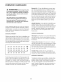
EXERCISE INTENSITY
Whether your goal is to burn fat or to strengthen your
cardiovascular system, exercising at the proper inten-
sity is the key to achieving results. You can use your
heart rate as a guide to find the proper intensity level.
The chart below shows recommended heart rates for
fat burning and aerobic exercise.
165 I55 145 140 130 I25 115 _
145 I38 I30 125 118 110 103 _
125 i20 115 1]0 I05 95 90
20 30 40 50 60 70 80
To find the proper intensity level, find your age at the
bottom of the chart (ages are rounded off to the near-
est ten years). The three numbers listed above your
age define your "training zone." The lowest number is
the heart rate for fat burning, the middle number is the
heart rate for maximum fat burning, and the highest
number is the heart rate for aerobic exercise.
Burning Fat--To burn fat effectively, you must exer-
cise at a low intensity level for a sustained period of
time. During the first few minutes of exercise, your
body uses carbohydrate calories for energy. Only after
the first few minutes of exercise does your body begin
to use stored fat calories for energy. If your goal is to
burn fat, adjust the intensity of your exercise until your
heart rate is near the lowest number in your training
zone. For maximum fat burning, exercise with your
heart rate near the middle number in your training
zone.
Aerobic Exercise--if your goal is to strengthen your
cardiovascular system, you must perform aerobic
exercise, which is activity that requires large amounts
of oxygen for prolonged periods of time. For aerobic
exercise, adjust the intensity of your exercise until
your heart rate is near the highest number in your
training zone.
WORKOUT GUIDELINES
Warming Up--Start with 5 to 10 minutes of stretching
and light exercise. A warm-up increases your body
temperature, heart rate, and circulation in preparation
for exercise.
Training Zone Exercise--Exercise for 20 to 30 min-
utes with your heart rate in your training zone. (During
the first few weeks of your exercise program, do not
keep your heart rate in your training zone for longer
than 20 minutes.) Breathe regularly and deeply as you
exercise-never hold your breath.
Cooling Down--Finish with 5 to 10 minutes of
stretching. Stretching increases the flexibility of your
muscles and helps to prevent post-exercise problems.
EXERCISE FREQUENCY
To maintain or improve your condition, complete three
workouts each week, with at least one day of rest
between workouts. After a few months of regular exer-
cise, you may complete up to five workouts each
week, if desired. Remember, the key to success is to
make exercise a regular and enjoyable part of your
everyday life.
16

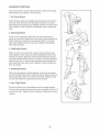
SUGGESTED STRETCHES
The correct form for several basic stretches is shown at the right.
Move slowly as you stretch--never bounce.
1. Toe Touch Stretch
Stand with your knees bent slightly and slowly bend forward from
your hips. Allow your back and shoulders to relax as you reach
down toward your toes as far as possible. Hold for 15 counts, then
relax. Repeat 3 times. Stretches: Hamstrings, back of knees and
back.
2. Hamstring Stretch
Sit with one leg extended. Bring the sole of the opposite foot
toward you and rest it against the inner thigh of your extended leg.
Reach toward your toes as far as possible. Hold for 15 counts,
then relax. Repeat 3 times for each leg. Stretches: Hamstrings,
lower back and groin.
3. Calf/Achilles Stretch
With one leg in front of the other, reach forward and place your
hands against a wall. Keep your back leg straight and your back
foot flat on the floor. Bend your front leg, lean forward and move
your hips toward the wall. Hold for 15 counts, then relax. Repeat 3
times for each leg. To cause further stretching of the achilles ten-
dons, bend your back leg as well. Stretches: Calves, achilles ten-
dons and ankles.
4. Quadriceps Stretch
With one hand against a wall for balance, reach back and grasp
one foot with your other hand. Bring your heel as close to your but-
tocks as possible. Hold for 15 counts, then relax. Repeat 3 times
for each leg. Stretches: Quadriceps and hip muscles.
5. inner Thigh Stretch
Sit with the soles of your feet together and your knees outward.
Pull your feet toward your groin area as far as possible. Hold for 15
counts, then relax. Repeat 3 times. Stretches: Quadriceps and hip
muscles.
5
f
\
17

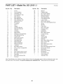
PART LISTmlVlodel No. 831.21811.1 R1010A
Key No. Qty. Description Key No. Qty. Description
1 1 Frame 38 2 Magnet
2 1 Front Stabilizer 39 1 Flywheel Axle
3 2 Handlebar Cap 40 2 M10 Small Washer
4 2 Front Stabilizer Cap 41 5 M4 x 25mm Screw
5 1 Seat Frame 42 3 M8 Split Washer
6 1 Rear Stabilizer 43 1 Reed Switch/Wire
7 2 Seat Handle Cap 44 1 Crank Bearing Set
8 2 Rear Stabilizer Cap 45 1 Lower Cable
9 1 Adjustment Knob 46 2 M8 Curved Washer
10 7 M8 Locknut 47 9 M4 x 15mm Self-tapping Screw
11 1 C-magnet 48 1 Spring
12 1 Seat 49 1 Bracket
13 1 Upright 50 2 Foam Grip
14 1 Left Seat Bracket 51 1 M6 x 45mm Bolt
15 1 Right Seat Bracket 52 1 Extension Wire
16 1 Console 53 1 Handlebar
17 1 Left Shield 54 4 M8 Washer
18 1 Right Shield 55 1 M5 x 40mm Screw
19 1 Resistance Control/Cable 56 1 Frame Bushing
20 1 Seat Frame Bushing 57 2 Bumper
21 1 Crank/Pulley 58 4 Square Cap
22 1 Reed Switch Clamp 59 2 Seat Handle
23 1 M8 x 20mm Bolt 60 1 Backrest
24 1 Left Pedal/Strap 61 8 M6 x 35mm Button Screw
25 2 6000Z Bearing 62 2 M8 x 125mm Bolt
26 1 Right Pedal/Strap 63 6 M6 Locknut
27 1 Resistance Knob 64 4 M6 x 30mm Button Bolt
28 2 U-bracket 65 2 M10 Locknut
29 2 M4 x 8mm Screw 66 2 M4 x 5mm Self-tapping Screw
30 2 M10 x 75mm Carriage Bolt 67 1 M5 Curved Washer
31 2 Eyebolt 68 8 M6 Washer
32 1 M6 Nut 69 4 M6 Curved Washer
33 2 M10 x 65mm Button Screw 70 2 M4 Washer
34 3 M8 x 20mm Button Screw 71 1 Seat Frame Cap
35 1 Drive Belt * - User's Manual
36 2 M8 x 65mm Button Bolt * - Assembly Tool
37 1 Flywheel
Note: Specifications are subject to change without notice. For information about ordering replacement parts, see
the back cover of this manual, if a part is missing, call 1-866-699-3756. *These parts are not illustrated.
18

EXPLODED DRAWING--IVlodel No. 831.21811.1 mOlOA
59
69
61
, 68
_61 67
64 34
4,,
12 34
47
\
41
49
41
44
25
38 39
; 66 51
48
56
37
28
63
65
30
35
19

iiiiiiiiiiiiiiiiii¸'
iiiiiiiiiiiiiiiiii
iiiiiiiiiiiiiiiiii
iiiiiiiiiiiiiiiiii
iiiiiiiiiiiiiiiiii
iiiiiiiiiiiiiiiiii
iiiiiiiiiiiiiiiiii
iiiiiiiiiiiiiiiiii
iiiiiiiiiiiiiiiiii
iiiiiiiiiiiiiiiiii
iiiiiiiiiiiiiiiiii
iiiiiiiiiiiiiiiiii
iiiiiiiiiiiiiiiiii
iiiiiiiiiiiiiiiiii
iiiiiiiiiiiiiiiiii
iiiiiiiiiiiiiiiiii
iiiiiiiiiiiiiiiiii
iiiiiiiiiiiiiiiiii
iiiiiiiiiiiiiiiiii
iiiiiiiiiiiiiiiiii
iiiiiiiiiiiiiiiiii
iiiiiiiiiiiiiiiiii
iiiiiiiiiiiiiiiiii
iiiiiiiiiiiiiiiiii
iiiiiiiiiiiiiiiiii
iiiiiiiiiiiiiiiiii
iiiiiiiiiiiiiiiiii
iiiiiiiiiiiiiiiiii
iiiiiiiiiiiiiiiiii
iiiiiiiiiiiiiiiiii
Your Home
For repair--in your home--of all major brand appliances, lawn and garden equipment,
or heating and cooling systems, no matter who made it, no matter who sold it!
For the replacement parts, accessories, and user's manuals that you need to do-it-yourself.
For Sears professional installation of home appliances
and items like garage door openers and water heaters.
1-800-4-MY-HOME ® (1-800-469-4663)
Call anytime, day or night (U.S.A. and Canada)
www.sears.com www.sears.ca
Our Home
For repair of carry-in items like vacuums, lawn equipment,
and electronics, call or go on-line for the location of your nearest
Sears Parts & Repair Center.
1-800-488-1222 Call anytime, day or night (U.S.A. only)
www.sears.com
To purchase a protection agreement (U.S.A.)
or maintenance agreement (Canada) on a product serviced by Sears:
1-800-827-6655 (U.S.A.) 1-800-361-6665 (Canada)
Para pedir servicio de reparaci6n a domicilio, y para ordenar piezas:
iiiiiiiiiiiiiiiii
iiiiiiiiiiiiiiiii
iiiiiiiiiiiiiiiii
iiiiiiiiiiiiiiiii
iiiiiiiiiiiiiiiii
iiiiiiiiiiiiiiiii
iiiiiiiiiiiiiiiii
iiiiiiiiiiiiiiiii
iiiiiiiiiiiiiiiii
iiiiiiiiiiiiiiiii
iiiiiiiiiiiiiiiii
iiiiiiiiiiiiiiiii
iiiiiiiiiiiiiiiii
iiiiiiiiiiiiiiiii
iiiiiiiiiiiiiiiii
iiiiiiiiiiiiiiiii
iiiiiiiiiiiiiiiii
iiiiiiiiiiiiiiiii
iiiiiiiiiiiiiiiii
iiiiiiiiiiiiiiiii
iiiiiiiiiiiiiiiii
iiiiiiiiiiiiiiiii
iiiiiiiiiiiiiiiii
iiiiiiiiiiiiiiiii
iiiiiiiiiiiiiiiii
iiiiiiiiiiiiiiiii
iiiiiiiiiiiiiiiii
iiiiiiiiiiiiiiiii
iiiiiiiiiiiiiiiii
iiiiiiiiiiiiiiiii
iiiiiiiiiiiiiiiii
iiiiiiiiiiiiiiiii
iiiiiiiiiiiiiiiii
iiiiiiiiiiiiiiiii
iiiiiiiiiiiiiiiii
iiiiiiiiiiiiiiiii
iiiiiiiiiiiiiiiii
iiiiiiiiiiiiiiiii
iiiiiiiiiiiiiiiii
iiiiiiiiiiiiiiiii
iiiiiiiiiiiiiiiii
iiiiiiiiiiiiiiiii
iiiiiiiiiiiiiiiii
iiiiiiiiiiiiiiiii
iiiiiiiiiiiiiiiii
iiiiiiiiiiiiiiiii
iiiiiiiiiiiiiiiii
iiiiiiiiiiiiiiiii
iiiiiiiiiiiiiiiii
iiiiiiiiiiiiiiiii
iiiiiiiiiiiiiiiii
iiiiiiiiiiiiiiiii
iiiiiiiiiiiiiiiii
iiiiiiiiiiiiiiiii
iiiiiiiiiiiiiiiii
iiiiiiiiiiiiiiiii
iiiiiiiiiiiiiiiii
iiiiiiiiiiiiiiiii
iiiiiiiiiiiiiiiii
iiiiiiiiiiiiiiiii
iiiiiiiiiiiiiiiii
iiiiiiiiiiiiiiiii
iiiiiiiiiiiiiiiii
iiiiiiiiiiiiiiiii
iiiiiiiiiiiiiiiii
iiiiiiiiiiiiiiiii
iiiiiiiiiiiiiiiii
iiiiiiiiiiiiiiiii
iiiiiiiiiiiiiiiii
iiiiiiiiiiiiiiiii
iiiiiiiiiiiiiiiii
iiiiiiiiiiiiiiiii
iiiiiiiiiiiiiiiii
iiiiiiiiiiiiiiiii
iiiiiiiiiiiiiiiii
iiiiiiiiiiiiiiiii
iiiiiiiiiiiiiiiii
iiiiiiiiiiiiiiiii
iiiiiiiiiiiiiiiii
iiiiiiiiiiiiiiiii
iiiiiiiiiiiiiiiii
iiiiiiiiiiiiiiiii
iiiiiiiiiiiiiiiii
iiiiiiiiiiiiiiiii
iiiiiiiiiiiiiiiii
iiiiiiiiiiiiiiiiiii
iiiiiiiiiiiiiiiiiii
iiiiiiiiiiiiiiiiiii
iiiiiiiiiiiiiiiiiii
iiiiiiiiiiiiiiiiiii
iiiiiiiiiiiiiiiiiii
iiiiiiiiiiiiiiiiiii
@Registered Trademark / TMTrademark / SMService Mark of Sears Brands, LLC
@ Marca Registrada / TMMarca de Fabrica / SMMarca de Servicio de Sears Brands, LLC
f
90 DAY FULL WARRANTY
If this Bike Exerciser fails due to a defect in material or workmanship within 90 days of the date of pur-
chase, call 1-800-4-MY-HOME ®(1-800-469-4663 to arrange for free repair (or replacement if repair
proves impossible).
This warranty does not apply when the Bike Exerciser is used commercially or for rental purposes.
This warranty gives you specific legal rights, and you may also have other rights which vary from state
to state.
Sears, Roebuck and Co., Hoffman Estates, IL 60179
J
J
Part No. 302821 R1010A Printed in China © 2010 ICON IP, Inc.
-
 1
1
-
 2
2
-
 3
3
-
 4
4
-
 5
5
-
 6
6
-
 7
7
-
 8
8
-
 9
9
-
 10
10
-
 11
11
-
 12
12
-
 13
13
-
 14
14
-
 15
15
-
 16
16
-
 17
17
-
 18
18
-
 19
19
-
 20
20


Weslo 831.21811.1 User manual
- Type
- User manual
- This manual is also suitable for
Ask a question and I''ll find the answer in the document
Finding information in a document is now easier with AI
Related papers
-
Weslo Pursuit G 3.8 User manual
-
-
-
-
-
-
-
-
-
Other documents
-
NordicTrack Gx5.1 Bike User manual
-
ProForm PFEVEX74712 Owner's manual
-
Pro-Form PFEX71608.2 User manual
-
-
-
-
-
-
Sears GL 36 User manual
-