VRF Air-Conditioner
Installation Manual
FORM NO.:YDEC IOM-EN(1212)

VRF Air-Conditioner IOM

VRF Air-Conditioner IOM
Contents
1. SAFETY CAUTIONS ....................................................................................................................... 1
2. BEFORE INSTALLATION ................................................................................................................ 1
3. SELECTION OF INSTALLATION POSITION ...................................................................................... 2
4. INSTALLATION OF INDOOR UNIT .................................................................................................. 2
5. INSTALLATION OF REFRIGERANT PIPING ...................................................................................... 4
6. INSTALLATION OF DRAINAGE PIPING ........................................................................................... 5
7. ELECTRIC CONNECTION ............................................................................................................... 6

VRF Air-Conditioner IOM
1
1. Safety Cautions
Please carefully read this "Safety Cautions" before
installing air conditioner so as to ensure correct
installation.
The following cautions are divided into two categories,
related to safety and of great importance, please
carefully read.
Warning…Inattention will lead to death or
serious injury.
Caution…Inattention will lead to injury or
machine damage, and may also cause serious injury
according to different conditions.
Installation operation must be conducted by
professional personnel. Do not conduct without
approval.
Please install the air conditioner in a solid place
sufficient to bear the weight.
Instable base may lead to air conditioner falling
and cause damage.
Please use separate circuit for power supply. The
operation of all the electric parts must be in
accordance with the local laws and specifications
as well as this instruction.
The operation shall be conducted by the
electrician with professional qualification.
Insufficient capacity or improper electric
operation may cause electric shock or fire hazard.
Use the specification designated wires; all the
wires shall be connected well to make connecting
terminal and wire free from external force
drawing.
Poor connection and improper installation may
cause fire hazard.
Straighten out and lay flat when connecting power
line, remote controller and wire controller line so
as to make electric parts and wire slot box cover
fastened down.
If any refrigerant gas leakage in installation,
immediately open door and window for
ventilation.
The refrigerant gas will generate toxic gas when
meeting combustion sources such as air heater,
furnace and stove.
Please power off first before touching electronic
parts.
Do not touch the switch with wet hand.
Touching switch with wet hand may cause electric
shock.
Air conditioner must be earthed.
Earthing wire shall not be connected to gas pipe,
tap water pipe, lightening rod and telephone line.
Poor earthing may lead to electric shock accident.
Leakage earthing leakage breaker must be
installed.
If leakage earthing breaker is not installed, there
will be electric shock hazard or fire hazard.
Please arrange drainage piping according to this
instruction to guarantee smooth drainage, and
insulate the piping in case of condensed water
accumulation.
Improper piping may lead to water leakage and
soak household items.
Air conditioner, power line and connecting line
shall be far away from more than 1m at least from
such electrical equipment as television set and
radio to prevent from interference of
electromagnetic wave and noise.
In the room equipped with fluorescent lamp
(inverter or quick start type), the signal
transmission distance of the remote controller may
not reach the preset value.
The indoor machine shall be away from
fluorescent lamp as far as possible.
Installation should not be conducted in the
following places:
(a) Place where mineral oil smoke or mist or steam
is diffused, for example, kitchen.
Plastic parts may be deteriorated and damaged.
(b) Place where there is corrosive gas such as sulfur
dioxide.
Copper pipe or welding part may be corroded to
cause refrigerant leakage.
(c) Place which is close to the machine generating
electromagnetic wave.
Electromagnetic wave may influence the control
system to make the air conditioner incapable of
normally operating.
(d) Place where there is combustible gas leakage,
carbon fiber or combustible dust floating, or
volatile combustible placing such as gasoline or
diluent.
The use of air conditioner in such places may
cause fire hazard.
Please do not touch the fin of the heat exchanger.
Improper touch may cause machine damage and
personal injury.
Please pay special attention to product handling.
Do not handle by lifting PP strap in case of PP
strap rupture to damage unit and harm person.
2. Before Installation
Air conditioner shall not be unsealed before
moved to the installation site. If it is necessary to
unseal, measures shall be taken after unsealing to
avoid damaging or scratching air conditioner.
When moving the air conditioner during or after
unsealing, do not apply force to refrigerant piping,
drainage pipe or other plastic parts in order to
avoid damaging air conditioner.
Before air conditioner installation, please confirm
whether the refrigerant used for the unit is R22 or
Warning

VRF Air-Conditioner IOM
2
R410a and whether it is consistent with that of
outdoor unit.
For the installation of outdoor unit, please refer to
the installation and operation instructions attached
for outdoor unit.
3. Selection of Installation Position
Installation position conditions:
Ceiling strength shall be sufficient to bear the
weight of indoor unit; if not, reinforce first.
Guarantee good ventilation and make gas flow
free from obstructions shielding.
Condensed water is capable of being discharged
smoothly.
There is no combustible gas leakage hazard.
Ensure adequate installation space.
Piping length of indoor unit and outdoor unit is
within an allowable range.
4. Installation of Indoor Unit
4.1 Open wall hole
Select installation position and determine pipe
passing direction and pipe outlet position.
Select drill bit according to machine model and
use electric hammer or diamond to open wall
hole.
Wall hole size in general: recommended wall hole
diameter Φ90mm for below 056 type and
Φ150mm for above 071 type.
Keep clear of the walls with wire or foreign
matters inside and outside and the superhard walls
as much as possible in holing; the hole inside shall
be 0.5cm~1cm higher than outside considering
drainage; wall hole passing through outlet pipe of
indoor unit side shall be slightly lower than the
indoor unit downside; for holing with diamond,
plastic cloth shall be sticked to wall or other
method may be adopted to prevent water flow to
wall; for holing with electric hammer, dust
prevention measures shall be taken.
4.2 Install the unit
Install Φ10 hoisting bolts (4).
After the unit hoisting, conduct piping and wiring
work in ceiling, and determine the outlet direction
of piping after installation site selection.
Especially on the occasion with existing ceiling,
please pull refrigerant piping, drainage pipe,
indoor and outdoor connecting line and remote
controller line to a connection position before
hanging machine.
Installation method for hoisting bolt.
Match with the existing structure and arrange
thread pitch according to the following shown
machine dimension.
Wooden occasion: arrange hoisting bolt by
mounting square bar on beam
Steel frame occasion: arrange and directly use
supporting angle steel
Existing concrete blank occasion:
Newly prepared concrete blank occasion:
Square bar
Hoisting bolt
Hanging bolt
Hanging bolt
Supporting angle steel
Ceiling
Beam
cm

VRF Air-Conditioner IOM
3
Seat installation method.
Please use embedded bolt, expansion bolt, etc.;
the bolt material shall be high-quality carbon steel
(subjected to surface copper plating or other
rust-proof treatment) or stainless steel.
4.3 Install indoor unit
Use pulley, etc. to hoist indoor unit to hoisting
bolt; use gradienter, etc. to install indoor unit
horizontally; otherwise, it may cause water
leakage.
For embedded type installation, the procedure is
similar to hoisting mode, but hole must be opened
on the ceiling before installation, with the
specification as follows: 1170×610 for 028-112
type and 1600×610 for 140-160 type; take down
the right and left cover plates of indoor unit and
then embed one half of main body into the ceiling,
and only expose rear cover plate and head cover.
For seat installation, use gradienter to install
Hoisting bolt
Hoisting bolt
Hoisting support
Hoisting support
Hoisting parts
Nut
Gasket
Side plate
Wall
Wedge bolt
Drainage outlet
Connector at gas side of cooling medium piping
Connector at liquid side of cooling medium piping
(Blade shape
Insertion)
(Slide insertion)
S
teel bar
Embedding screw bolt
(Pipe hang
ing and embedding
screw bolt)

VRF Air-Conditioner IOM
4
indoor unit horizontally and maintain the main
body vertical to the floor. Dismantle pump, small
defrosting tray and water level switch before
installation, strip off the insulated shield of water
level switch connecting line and then screw
together to make short circuit, directly connect
drainage pipe in accessories to the main defrosting
tray outlet (select left or right water outlet of
defrosting tray according to actual installation
condition).
Model A
B
C
D
E
F
G
H
YDEC028-112
1245
680
150
760
450
1119
200
240
YDEC140-160
1670
680
150
1070
450
1542
200
240
5. Installation of Refrigerant Piping
The piping at gas side and liquid side of
refrigerant shall be subjected to thermal insulation,
if not, the piping surface will have dew.
Please use thermal insulation material which is
capable of withstanding above 120 high
temperature. Please strengthen thermal insulation
for refrigerant piping according to the installation
environment, otherwise, the surface of the thermal
insulation material may dew and frost.
Please comply with the following items:
Coat fatty oil or ether oil at horn mouth (inside
and outside) when connecting horn mouth nut.
Only use the horn mouth nut attached by the unit.
Other horn mouth nut may lead to refrigerant
leakage.
Please clamp flat or seal the pipe end in order to
prevent dust, moisture or other foreign matter
entering into pipe.
Except designated refrigerant, anything, for
example, air, shall not mix into refrigerating
circuit.
Before welding refrigerant piping, please conduct
nitrogen replacement or fill nitrogen into piping in
welding, and finally connect with indoor unit by
horn mouth.
When filling nitrogen into piping in welding,
guarantee to control the pressure with reducing
valve as 0.02MPa (0.2kgf/cm
2
) (like the feel of
breeze blowing cheek).
Do not use welding flux when welding refrigerant
piping connector. Please use copper base brazing
filler metal without welding flux.
The use of welding flux containing chlorine or
fluorine may corrode the purity of piping or
refrigerating system.
5.1 Piping connection
When connecting and dismantling piping to/from
air conditioner, simultaneously use an ordinary
spanner and a torque spanner.
For relevant tightening torque, please refer to the
following table.
Pipe diameter
Tightening torque
(N.m)
6.35(1/4") 14.2~17.2
9.53(3/8") 32.7~39.9
12.7(1/2") 49.5~60.3
15.88(5/8") 61.8~75.4
If it is necessary to install unit without torque
spanner, comply with the following method:
When using spanner to tighten the horn mouth nut,
the tightening torque on some point may suddenly
increase. Further tighten the horn mouth nut from
this position to the angle shown in the following
table.
Pipe diameter
Angle
tightened
further
Length of
recommended
tool arm
6.35(1/4") 60°~90°
~150mm
9.53(3/8") 60°~90°
~200mm
12.7(1/2") 45°~75°
~250mm
15.88(5/8") 45°~75°
~300mm
Caution
Caution
Hook
Dismantle pump assembly
Connect defrosting tray with
drainage pipe
Bolt
Gasket
Torque spanner
Ordinary spanner
Piping connector
Horn mouth nut

VRF Air-Conditioner IOM
5
Excessive tightening may damage horn mouth and
lead to refrigerant leakage.
5.2 Air tightness leakage detection
Conduct air tightness leakage detection
confirmation at the end of piping work.
Leakage detection method:
(a) Fill dry compressed nitrogen into indoor unit and
piping system, and slowly boost the pressure to
4.3MPa;
(b) After maintaining pressure for 10min, coat soapy
water or other foaming agent at the connection
position such as weld and thread joint, and
observe whether there is leakage;
(c) If any leakage, tighten or repair weld leaking
position after pressure relief.
(d) Fill into dry compressed nitrogen again and
slowly boost the pressure to 4.3MPa;
(e) Start to record the reading of pressure gauge after
maintaining pressure for 6h, and then record the
reading of pressure gauge again after 24h;
(f) If no pressure drop, then the air tightness is
qualified. If any pressure drop, find out the
leakage point and repair, and then repeat the
above d and e procedures until qualified.
Pressure reading is related to temperature
variation, so the temperature variation factor shall
be considered when judging whether there is
pressure drop. The relation of pressure correction
value and temperature variation is:
−
+
+
∗=∆ 1
273
273
1
2
1
t
t
PP
PPP
∆
−
=
2correction
P--Pressure correction value (bar)
P
correction
---Corrected pressure value (bar)
P
1
---The first pressure reading (bar)
P
2
---The second pressure reading (bar)
t
1
---Temperature at the first pressure reading ( )
t
2
---Temperature at the second pressure reading
( )
In air tightness test, do not connect indoor unit
and outdoor unit, otherwise, nitrogen may leak to
outdoor unit.
5.3 Thermal insulation
If no leakage after inspection, respectively wrap
liquid pipe, gas pipe and each connecting position
with thick-enough heat-resistant polyethylene, and
conduct good thermal insulation.
Field piping must be connected to the piping
connecting part all the time. If poor thermal
insulation for piping, there will be dew outside
and scald if any touch.
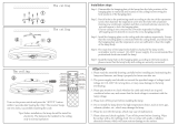
6. Installation of Drainage Piping
6.1 Drainage piping installation
In delivery, the drainage outlet is PVC pipe; in
connecting water pipe, please use auxiliary
sealing material and sleeve.
Conduct thermal insulation for drainage pipe of
indoor unit, otherwise, condensation may be
caused. The connecting part of indoor unit must
also be subjected to thermal insulation treatment.
Before installation, please confirm whether the
connection condition of pump defrosting tray and
the surface thermal insulation are intact.
For drainage pipe connection, use hard PVC
binding agent and confirm there is no leakage.
The junction of drainage pipe and drainage outlet
of indoor unit must be free from bearing any force,
including water pipe gravity.
The downward inclination of drainage pipe shall
be above (1/100) and the middle shall be free
from bending.
The transverse pull-out of drainage pipe shall be
within 20m. If the drainage pipe is longer, please
arrange a support to prevent bending.
Drainage system joints must be sealed against
water leakage.
The height from drainage pipe end to ground or
drainage channel bottom shall be larger than
50mm, and the drainage pipe end shall not be put
into water. When directly discharging condensed
water into foul ditch, bend drainage pipe upward
to a U-shaped water seal in order to avoid odor
entering into room through drainage pipe.
For concentrated construction of drainage pipe of
multiple indoor units during suspended ceiling
installation (with pump), arrange U-shaped bend
at the branch water pipe connecting each indoor
unit to prevent water return from main drainage
pipe.
For seat installation, dismantle pump assembly,
and directly connect the drainage pipe of
accessories to drainage outlet of defrosting tray.
Caution
Caution
Thermal insulation material
Incline downward
above 1/100

VRF Air-Conditioner IOM
6
Concentrated construction of drainage pipe of
multiple indoor units in seat installation (pump
must be dismantled) shall be in accordance with
the following figure.
6.2 Drainage test
Guarantee smooth drainage pipe connection and
check whether each joint is sealed.
Confirm by injecting water into air outlet. Inject
water into air outlet with jar or hose; pay attention
to slowly injecting until the drainage nozzle of
water pond has water flow.
At the end of preparation work, power on terminal
board and immediately start discharge pump in
refrigerating mode.
Check the drainage condition of discharge pump
after operating for a few minutes.
In seat installation, the method of drainage test is
to directly inject water slowly from air outlet until
the water outlet of drainage pipe end has water
discharge and observe whether the middle has
seepage along the pipeline.
7. Electric Connection
7.1 General
Power off before implementing any electric
operation.
All the purchased parts and materials as well as
electric operation must comply with the local laws
and regulations.
All the connection operation must be implemented
by professional electrician.
Line breaker or leakage breaker must be arranged
at power supply.
Earthing resistance must below 4Ω.
Air conditioner must be earthed reliably. Earthing
wire shall not be connected to gas pipe, tap water
pipe, lightening rod or telephone line.
Do not power on before the end of all the electric
operation.
The terminal of the same power supply shall not
be connected with two wires with different
diameters.
Please use the power line with specified
specification, firmly connect and ensure terminal
free from external force drawing.
Terminal screw should not be too tight or too
loose. Too tight will damage the terminal and too
loose may lead to poor contact and cause excess
heating to trigger hazard.
7.2 Unit power distribution
Please refer to the following figure for power
distribution of indoor unit and outdoor unit.
A set of independent cooling medium system shall
use an independent switch control; multiple
systems shall not use a switch control and partial
indoor unit in a system and indoor unit of other
system shall also not share a switch control.
About 10cm as much as possible
Incline downward
above 1/100
Drainage pipe
Inject water into air
outlet
Arrange drainage
pipe to U shape
against return
Wrap drainage pipe and its
connection posi
tion with
insulating pipe against
condensation
S-shaped
Bending
I
ndoor unit
Outdoor
unit

VRF Air-Conditioner IOM
7
7.3 Connection of indoor unit power line
The power supply connection for indoor unit is detailed in electric schematic diagram on electric control box.
Wiring specification is RVV2X2.5+1.5.
7.4 Type setting
Type setting is detailed in the electric schematic diagram on the electric control box.
7.5 Communication wire connection
Note: Inlet and outlet lines (TB2 inlet and TB3 outlet) of indoor unit shall not be reversed,
otherwise
, there will be fault and
the unit can't be started.
Recommended model of communication wire is RVSP2X 0.75.
"TB2 inlet" connects the communication wire from outdoor unit communication terminals (A and B) or from the
former indoor unit (TB3).
Communication wire of "TB3 outlet" connects to the communication port of the next indoor unit (TB2 inlet).
Inlet and outlet lines (TB2 inlet and TB3 outlet) of indoor unit shall not be reversed, otherwise, there will be fault
and the unit can't be started.
Connect according to the diagram, do not allow A and B polarity connection error, otherwise, communication
failure or controller damage may be caused.
In order to avoid signal interference, the communication wire must use shielding wire, and the shielding layer
shall be earthed.
The communication wire exceeding the specific length may cause air conditioner out of service due to
communication problem: communication wire length ≤500m and total length ≤1000m.
7.6 Install the controller
Install the wire controller on the pre-reserved site on the wall.
Carcassing for communication wiring should be ready before installation the controller. The recommended
Outdoor unit

VRF Air-Conditioner IOM
8
communication line is RVSP2 0.75. Be sure to pull the wires through the PVC conduit.
Note: the communication wire and PVC conduit are the field supplied parts.
7.7 Connect the wire controller and indoor unit
Group control can be realized through the wire controller. One wire controller can connect to max 4 indoor
units.
The indoor units in one group should be connected in one and same power supply to guarantee normal
initialization of wire controller when power on.
Connection sketch of indoor unit and wire controller:
(a) When one wire controller connecting only one indoor unit: (refer to Fig. 13)
(b) When one wire controller connecting multi indoor units: (refer to Fig. 14)
Fig. 13
One wire controller connects to one indoor unit
Fig. 14
One wire controller connects to multi indoor units

9
YDEC IOM
-EN(1212)
NONE
YDEC IOM (0812)
/