YSI IQ SensorNet MIQ/MC-MOD & MIQ/MC-PR Module User manual
- Category
- Software manuals
- Type
- User manual
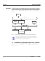
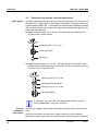
YSI IQ SensorNet MIQ/MC-MOD & MIQ/MC-PR Module provides a gateway between Profibus or Modbus RTU and RS-485 networks. These modules can be used to connect the IQ SensorNet system to a Profibus or Modbus RTU network, allowing for the exchange of data between the two systems. The MIQ/MC-MOD module uses the Modbus RTU protocol over RS-485, which is a widely used industrial protocol for communication between devices. The MIQ/MC-PR module uses the Profibus protocol, which is a fieldbus protocol commonly used in industrial automation systems.
YSI IQ SensorNet MIQ/MC-MOD & MIQ/MC-PR Module provides a gateway between Profibus or Modbus RTU and RS-485 networks. These modules can be used to connect the IQ SensorNet system to a Profibus or Modbus RTU network, allowing for the exchange of data between the two systems. The MIQ/MC-MOD module uses the Modbus RTU protocol over RS-485, which is a widely used industrial protocol for communication between devices. The MIQ/MC-PR module uses the Profibus protocol, which is a fieldbus protocol commonly used in industrial automation systems.


-
 1
1
-
 2
2
-
 3
3
-
 4
4
-
 5
5
-
 6
6
-
 7
7
-
 8
8
-
 9
9
-
 10
10
-
 11
11
-
 12
12
-
 13
13
-
 14
14
-
 15
15
-
 16
16
-
 17
17
-
 18
18
-
 19
19
-
 20
20


YSI IQ SensorNet MIQ/MC-MOD & MIQ/MC-PR Module User manual
- Category
- Software manuals
- Type
- User manual
YSI IQ SensorNet MIQ/MC-MOD & MIQ/MC-PR Module provides a gateway between Profibus or Modbus RTU and RS-485 networks. These modules can be used to connect the IQ SensorNet system to a Profibus or Modbus RTU network, allowing for the exchange of data between the two systems. The MIQ/MC-MOD module uses the Modbus RTU protocol over RS-485, which is a widely used industrial protocol for communication between devices. The MIQ/MC-PR module uses the Profibus protocol, which is a fieldbus protocol commonly used in industrial automation systems.
Ask a question and I''ll find the answer in the document
Finding information in a document is now easier with AI
Related papers
-
YSI IQ SensorNet Field Bus Linking User manual
-
-
-
-
-
-
-
-
-
Other documents
-
 Rule 401FC Operating instructions
-
wtw IQ SENSOR NET MIQ/A Operating instructions
-
-
-
 Bell & Gossett BG100 User manual
-
-
-
-
-

