ESAB 300Pi Transtig Welding Inverter User manual
- Category
- Welding System
- Type
- User manual

A-11419
Service Manual
Revision: AC Issue Date: April 23, 2015 Manual No.: 0-5206
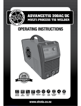
Operating Features:
200AC/DC
INVERTER
ARC WELDING MACHINE

WE APPRECIATE YOUR BUSINESS!
Congratulations on your new Cigweld product. We are proud
to have you as our customer and will strive to provide you with
the best service and reliability in the industry. This product
is backed by our extensive warranty and world-wide service
network. To locate your nearest distributor or service provider call
+1300 654 674, or visit us on the web at www.cigweld.com.cn
This Service Manual has been designed to instruct you on the correct
use and operation of your CIGWELD product. Your satisfaction with
this product and its safe operation is our ultimate concern. Therefore
please take the time to read the entire manual, especially the Safety
Precautions. They will help you to avoid potential hazards that may
exist when working with this product.
YOU ARE IN GOOD COMPANY!
The Brand of Choice for Contractors and Fabricators Worldwide.
CIGWELD is the Market Leading Brand of Arc Welding Products
for Victor Technologies Inc. We are a mainline supplier to major
welding industry sectors in the Asia Pacific and emerging global
markets including; Manufacturing, Construction, Mining, Automotive,
Engineering, Rural and DIY.
We distinguish ourselves from our competition through market-
leading, dependable products that have stood the test of time. We
pride ourselves on technical innovation, competitive prices, excellent
delivery, superior customer service and technical support, together
with excellence in sales and marketing expertise.
Above all, we are committed to develop technologically advanced
products to achieve a safer working environment for industry
operators.

!
WARNINGS
Read and understand this entire Manual and your employer’s safety practices before installing,
operating, or servicing the equipment.
While the information contained in this Manual represents the Manufacturer’s best judgement,
the Manufacturer assumes no liability for its use.
Welding Power Supply
Service Manual Number 0-5206 for:
WeldSkill 200AC/DC Plant Part Number W1006200
Published by:
CIGWELD Pty Ltd
71 Gower Street
Preston, Victoria, Australia, 3072
www.cigweld.com.au
Copyright 2012, 2013 by
CIGWELD
All rights reserved.
Reproduction of this work, in whole or in part, without written permission of the
publisher is prohibited.
The publisher does not assume and hereby disclaims any liability to any party for any
loss or damage caused by any error or omission in this Manual, whether such error
results from negligence, accident, or any other cause.
Publication Date: January 15, 2013
Record the following information for Warranty purposes:
Where Purchased: ____________________________________
Purchase Date: ____________________________________
Equipment Serial #: ____________________________________

TABLE OF CONTENTS
SECTION 1:
SAFETY INSTRUCTIONS AND WARNINGS ....................................................... 1-1
1.01 Arc Welding Hazards ....................................................................................... 1-1
1.02 Principal Safety Standards .............................................................................. 1-4
1.03 Declaration of Conformity ............................................................................... 1-5
1.04 Symbol Chart .................................................................................................. 1-6
1.05 Servicing Hazards ........................................................................................... 1-7
1.06 EMF Information ............................................................................................. 1-8
SECTION 2:
INTRODUCTION ...................................................................................... 2-1
2.01 How to Use This Manual ................................................................................. 2-1
2.02 Equipment Identification ................................................................................. 2-1
2.03 Receipt of Equipment ...................................................................................... 2-1
2.04 Description ..................................................................................................... 2-1
2.05 Transportation Methods .................................................................................. 2-1
SECTION 3:
SAFETY AND INSTALLATION ....................................................................... 3-1
3.01 Duty Cycle ....................................................................................................... 3-1
3.02 Specifications ................................................................................................. 3-2
3.03 Environment ................................................................................................... 3-3
3.04 Location .......................................................................................................... 3-3
3.05 High Frequency Introduction .......................................................................... 3-3
3.06 High Frequency Interference ........................................................................... 3-4
3.07 Electromagnetic Compatibility ........................................................................ 3-4
3.07 Volt-Ampere Curves ........................................................................................ 3-6
SECTION 4:
OPERATION ........................................................................................... 4-1
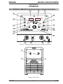
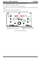
4.01 WELDSKILL 200AC/DC Power Source Controls, Indicators and Features ....... 4-1
4.02 WELDSKILL 200AC/DC - STICK Programming Mode ..................................... 4-6
4.03 WELDSKILL 200AC/DC – LIFT TIG and HF TIG Programming Mode ............. 4-7
4.04 Short Circuit Protection While Welding ......................................................... 4-10
4.05 Shielding Gas Regulator Operating Instructions ........................................... 4-11
4.06 Setup for TIG (GTAW) Welding ..................................................................... 4-13
4.07 Foot Control, Part No. W4015800 (Optional Accessory) ............................... 4-14
4.08 Setup for STICK (MMAW) Welding ............................................................. 4-16
SECTION 5:
THEORY OF OPERATION ............................................................................ 5-1
5.01 Inverter Design ............................................................................................... 5-1

TABLE OF CONTENTS
SECTION 6:
TROUBLESHOOTING ................................................................................ 6-1
6.01 Basic Troubleshooting-Power Source Faults ................................................... 6-1
6.02 Advanced Troubleshooting .............................................................................. 6-2
6.03 Test Equipment and Tools .............................................................................. 6-2
6.04 Visually Inspect ............................................................................................... 6-2
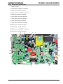
6.05 Preliminary DC Bus measurement of the main inverter board ........................ 6-3
6.06 Preliminary check of the main inverter board ................................................. 6-4
6.07 Check main input rectifier ............................................................................... 6-4
6.08 DC Bus voltage measurement ......................................................................... 6-4
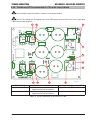
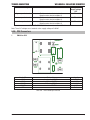
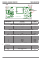
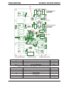
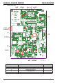
6.09 PCB Connectors .............................................................................................. 6-5
6.10 DIP switch settings, Control PCB .................................................................. 6-14
6.11 Calibration .................................................................................................... 6-15
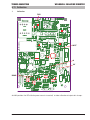
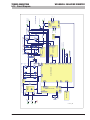
6.12 Main Circuit Description ............................................................................... 6-16
6.13 Circuit Diagram ............................................................................................. 6-17
SECTION 7:
DISASSEMBLY PROCEDURE ....................................................................... 7-1
7.01 Safety Precautions for Disassembly ............................................................... 7-1
7.02 Case Removal ................................................................................................. 7-1
7.03 Control Board Removal ................................................................................... 7-2
7.04 Auxiliary Power Supply PCB2 Removal .......................................................... 7-3
7.05 PCB3 Removal ................................................................................................ 7-4
7.06 PCB4 Removal ................................................................................................ 7-5
7.07 PCB5 Removal ................................................................................................ 7-5
7.08 Front Panel assembly Removal ...................................................................... 7-6
7.09 Front Panel (operator Interface) Circuit Board PCB Removal .......................... 7-7
7.10 Back Panel Removal ....................................................................................... 7-8
7.12 Main Power PCB2 Removal .......................................................................... 7-10
7.13 Power Switch S1, Fan and Power Cord Removal .......................................... 7-11
SECTION 8:
ASSEMBLY PROCEDURES .......................................................................... 8-1
8.01 Installing Main Power PCB1 ........................................................................... 8-1
8.02 Installing Main Power PCB2 ........................................................................... 8-2
8.03 Installing Front Panel ...................................................................................... 8-3
8.04 Installing Rear Panel ....................................................................................... 8-4
8.05 Installing PCB5 ............................................................................................... 8-5
8.06 Installing PCB4 ............................................................................................... 8-5
8.07 Installing PCB3 ............................................................................................... 8-6
8.08 Installing Auxiliary Power Supply PCB2 .......................................................... 8-6
8.09 Installing Control Board .................................................................................. 8-7
8.10 Installing Case ................................................................................................ 8-8
SECTION 9:
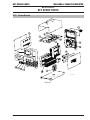
KEY SPARE PARTS ................................................................................... 9-1
9.01 Power Source ................................................................................................. 9-1


SAFETY INSTRUCTIONS AND WARNINGS WELDSKILL 200AC/DC INVERTER
Manual 0-5206 1-1
Safety Instructions and Warnings
1.01 Arc Welding Hazards
WARNING
ELECTRIC SHOCK can kill.
Touching live electrical parts can cause fatal shocks
or severe burns. The electrode and work circuit is
electrically live whenever the output is on. The input
power circuit and machine internal circuits are also live
when power is on. In semiautomatic or automatic wire
welding, the wire, wire reel, drive roll housing, and all
metal parts touching the welding wire are electrically
live. Incorrectly installed or improperly grounded
equipment is a hazard
1. Do not touch live electrical parts.
2. Wear dry, hole-free insulating gloves and body protection.
3. Insulate yourself from work and ground using dry insulating
mats or covers.
4. Disconnect input power or stop engine before installing or
servicing this equipment. Lock input power disconnect switch
open, or remove line fuses so power cannot be turned on
accidentally.
5. Properly install and ground this equipment according to its
Owner’s Manual and national, state, and local codes.
6. Turn off all equipment when not in use. Disconnect power to
equipment if it will be left unattended or out of service.
7. Use fully insulated electrode holders. Never dip holder in
water to cool it or lay it down on the ground or the work
surface. Do not touch holders connected to two welding
machines at the same time or touch other people with the
holder or electrode.
8. Do not use worn, damaged, undersized, or poorly spliced
cables.
9. Do not wrap cables around your body.
10. Ground the workpiece to a good electrical (earth) ground.
11. Do not touch electrode while in contact with the work (ground)
circuit.
12. Use only well-maintained equipment. Repair or replace
damaged parts at once.
13. In confined spaces or damp locations, do not use a welder
with AC output unless it is equipped with a voltage reducer.
Use equipment with DC output.
14. Wear a safety harness to prevent falling if working above floor
level.
15. Keep all panels and covers securely in place.
WARNING
ARC RAYS can burn eyes and skin; NOISE can dam-
age hearing.
Arc rays from the welding process produce intense
heat and strong ultraviolet rays that can burn eyes and
skin. Noise from some processes can damage hearing.
1. Use a Welding Helmet or Welding Faceshield fitted with a
proper shade of filter (see ANSI Z49.1 and AS 1674 listed in
Safety Standards) to protect your face and eyes when welding
or watching.
2. Wear approved safety glasses. Side shields recommended.
3. Use protective screens or barriers to protect others from flash
and glare; warn others not to watch the arc.
4. Wear protective clothing made from durable, flame-resistant
material (wool and leather) and foot protection.
5. Use approved ear plugs or ear muffs if noise level is high.
6. Never wear contact lenses while welding.
WARNING
FUMES AND GASES can be hazardous to your health.
Welding produces fumes and gases. Breathing these
fumes and gases can be hazardous to your health.
1. Keep your head out of the fumes. Do not breath the fumes.
SECTION 1:
SAFETY INSTRUCTIONS AND WARNINGS
!
WARNING
PROTECT YOURSELF AND OTHERS FROM POSSIBLE SERIOUS INJURY OR DEATH. KEEP CHILDREN AWAY. PACEMAKER WEARERS
KEEP AWAY UNTIL CONSULTING YOUR DOCTOR. DO NOT LOSE THESE INSTRUCTIONS. READ OPERATING/INSTRUCTION MANUAL
BEFORE INSTALLING, OPERATING OR SERVICING THIS EQUIPMENT.
Welding products and welding processes can cause serious injury or death, or damage to other equipment or property, if the operator
does not strictly observe all safety rules and take precautionary actions.
Safe practices have developed from past experience in the use of welding and cutting. These practices must be learned through study
and training before using this equipment. Some of these practices apply to equipment connected to power lines; other practices ap-
ply to engine driven equipment. Anyone not having extensive training in welding and cutting practices should not attempt to weld.
Safe practices are outlined in the European Standard EN60974-1 entitled: Safety in welding and allied processes Part 2: Electrical.
This publication and other guides to what you should learn before operating this equipment are listed at the end of these safety
precautions. HAVE ALL INSTALLATION, OPERATION, MAINTENANCE, AND REPAIR WORK PERFORMED ONLY BY QUALIFIED PEOPLE.

Safety Instructions and Warnings
1-2 Manual 0-5206
WELDSKILL 200AC/DC INVERTER SAFETY INSTRUCTIONS AND WARNINGS
2. If inside, ventilate the area and/or use exhaust at the arc to
remove welding fumes and gases.
3. If ventilation is poor, use an approved air-supplied respirator.
4. Read the Material Safety Data Sheets (MSDSs) and the
manufacturer’s instruction for metals, consumables, coatings,
and cleaners.
5. Work in a confined space only if it is well ventilated, or while
wearing an air-supplied respirator. Shielding gases used for
welding can displace air causing injury or death. Be sure the
breathing air is safe.
6. Do not weld in locations near degreasing, cleaning, or
spraying operations. The heat and rays of the arc can react
with vapours to form highly toxic and irritating gases.
7. Do not weld on coated metals, such as galvanized, lead, or
cadmium plated steel, unless the coating is removed from the
weld area, the area is well ventilated, and if necessary, while
wearing an air-supplied respirator. The coatings and any metals
containing these elements can give off toxic fumes if welded.
WARNING
WELDING can cause fire or explosion.
Sparks and spatter fly off from the welding arc.
The flying sparks and hot metal, weld spatter, hot
workpiece, and hot equipment can cause fires and
burns. Accidental contact of electrode or welding wire
to metal objects can cause sparks, overheating, or fire.
1. Protect yourself and others from flying sparks and hot metal.
2. Do not weld where flying sparks can strike flammable
material.
3. Remove all flammables within 35 ft (10.7 m) of the welding
arc. If this is not possible, tightly cover them with approved
covers.
4. Be alert that welding sparks and hot materials from welding
can easily go through small cracks and openings to adjacent
areas.
5. Watch for fire, and keep a fire extinguisher nearby.
6. Be aware that welding on a ceiling, floor, bulkhead, or
partition can cause fire on the hidden side.
7. Do not weld on closed containers such as tanks or drums.
8. Connect work cable to the work as close to the welding area
as practical to prevent welding current from travelling long,
possibly unknown paths and causing electric shock and fire
hazards.
9. Do not use welder to thaw frozen pipes.
10. Remove stick electrode from holder or cut off welding wire at
contact tip when not in use.
WARNING
FLYING SPARKS AND HOT METAL can cause injury.
Chipping and grinding cause flying metal. As welds
cool, they can throw off slag.
1. Wear approved face shield or safety goggles. Side shields
recommended.
2. Wear proper body protection to protect skin.
WARNING
CYLINDERS can explode if damaged.
Shielding gas cylinders contain gas under high
pressure. If damaged, a cylinder can explode. Since
gas cylinders are normally part of the welding process,
be sure to treat them carefully.
1. Protect compressed gas cylinders from excessive heat,
mechanical shocks, and arcs.
2. Install and secure cylinders in an upright position by chaining
them to a stationary support or equipment cylinder rack to
prevent falling or tipping.
3. Keep cylinders away from any welding or other electrical
circuits.
4. Never allow a welding electrode to touch any cylinder.
5. Use only correct shielding gas cylinders, regulators, hoses, and
fittings designed for the specific application; maintain them and
associated parts in good condition.
6. Turn face away from valve outlet when opening cylinder
valve.
7. Keep protective cap in place over valve except when cylinder is
in use or connected for use.
8. Read and follow instructions on compressed gas cylinders,
associated equipment, and CGA publication P-1 listed in Safety
Standards.

SAFETY INSTRUCTIONS AND WARNINGS WELDSKILL 200AC/DC INVERTER
Manual 0-5206 1-3
Safety Instructions and Warnings
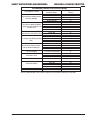
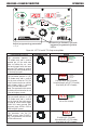
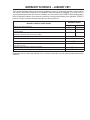
Recommended Protective Filters for Electric Welding
Description of Process
Approximate range of Weldi
ng
Current in Amps
Minimum Shade Number of
Filter(s)
Manual Metal Arc Welding covered
electrodes (MMAW)
Less than or equal to 100
8
100 to 200 10
200 to 300 11
300 to 400
12
Greater than 400
13
Gas Metal Arc Welding (GWAW)
(MIG) other than Aluminium and
Stainless Steel
Less than or equal to 150
10
150 to 250
11
250 to 300
12
300 to 400 13
Greater than 400 14
Gas Metal Arc Welding (GMAW)
(MIG) Aluminium and Stainless Steel
Less than or equal to 250
12
250 to 350
13
Gas Tungsten Arc Welding (GTAW
)
(TIG)
Less than or equal to 100 10
100 to 200
11
200 to 250
12
250 to 350
13
Greater than 350
14
Flux-cored Arc Welding (FCAW)
-with or without shielding gas.
Less than or equal to 300
11
300 to 400 12
400 to 500
13
Greater than 500
14
Air – Arc Gouging Less than or equal to 400 12
Plasma-Arc Cutting
50 to 100
10
100 to 400
12
400 to 800 14
Plasma-Arc Spraying — 15
Plasma-Arc Welding
Less than or equal to 20
8
20 to 100
10
100 to 400
12
400 to 800
14
Submerged Arc Welding
—
2(5)
Resistance Welding — Safety Spectacles or eye shield
Refer to standard AS/NZS 1338.1:1992 for comprehensive information regarding the above table.

Safety Instructions and Warnings
1-4 Manual 0-5206
WELDSKILL 200AC/DC INVERTER SAFETY INSTRUCTIONS AND WARNINGS
WARNING
MOVING PARTS can cause injury.
Moving parts, such as fans, rotors, and belts can cut fingers and
hands and catch loose clothing.
1. Keep all doors, panels, covers, and guards closed and
securely in place.
2. Stop engine before installing or connecting unit.
3. Have only qualified people remove guards or covers for
maintenance and troubleshooting as necessary.
4. To prevent accidental starting during servicing, disconnect
negative (-) battery cable from battery.
5. Keep hands, hair, loose clothing, and tools away from
moving parts.
6. Reinstall panels or guards and close doors when servicing
is finished and before starting engine.
!
WARNING
This product, when used for welding or cutting, pro-
duces fumes or gases which contain chemicals know
to the State of California to cause birth defects and, in
some cases, cancer. (California Health & Safety code
Sec. 25249.5 et seq.)
NOTE
Considerations About Welding And The Effects of Low
Frequency Electric and Magnetic Fields
The following is a quotation from the General Conclusions Section
of the U.S. Congress, Office of Technology Assessment, Biological
Effects of Power Frequency Electric & Magnetic Fields - Background
Paper, OTA-BP-E-63 (Washington, DC: U.S. Government Printing
Office, May 1989): “...there is now a very large volume of scientific
findings based on experiments at the cellular level and from studies
with animals and people which clearly establish that low frequency
magnetic fields and interact with, and produce changes in, biological
systems. While most of this work is of very high quality, the results
are complex. Current scientific understanding does not yet allow
us to interpret the evidence in a single coherent framework. Even
more frustrating, it does not yet allow us to draw definite conclu-
sions about questions of possible risk or to offer clear science-based
advice on strategies to minimize or avoid potential risks.”
To reduce magnetic fields in the workplace, use the following
procedures.
1. Keep cables close together by twisting or taping them.
2. Arrange cables to one side and away from the operator.
3. Do not coil or drape cable around the body.
4. Keep welding power source and cables as far away from body
as practical.
ABOUT PACEMAKERS:
The above procedures are among those also normally
recommended for pacemaker wearers. Consult your
doctor for complete information.
1.02 Principal Safety Standards
Safety in Welding and Cutting, ANSI Standard Z49.1, from American
Welding Society, 550 N.W. LeJeune Rd., Miami, FL 33126.
Safety and Health Standards, OSHA 29 CFR 1910, from Superinten-
dent of Documents, U.S. Government Printing Office, Washington,
D.C. 20402.
Recommended Safe Practices for the Preparation for Welding and
Cutting of Containers That Have Held Hazardous Substances, Ameri-
can Welding Society Standard AWS F4.1, from American Welding
Society, 550 N.W. LeJeune Rd., Miami, FL 33126.
National Electrical Code, NFPA Standard 70, from National Fire
Protection Association, Batterymarch Park, Quincy, MA 02269.
Safe Handling of Compressed Gases in Cylinders, CGA Pamphlet P-1,
from Compressed Gas Association, 1235 Jefferson Davis Highway,
Suite 501, Arlington, VA 22202.
Code for Safety in Welding and Cutting, CSA Standard W117.2, from
Canadian Standards Association, Standards Sales, 178 Rexdale
Boulevard, Rexdale, Ontario, Canada M9W 1R3.
Safe Practices for Occupation and Educational Eye and Face Pro-
tection, ANSI Standard Z87.1, from American National Standards
Institute, 1430 Broadway, New York, NY 10018.
Cutting and Welding Processes, NFPA Standard 51B, from Na-
tional Fire Protection Association, Batterymarch Park, Quincy, MA
02269.
Safety in welding and allied processes Part 1: Fire Precautions, AS
1674.1-1997 from SAI Global Limited, www.saiglobal.com.
Safety in welding and allied processes Part 2: Electrical, AS 1674.2-
2007 from SAI Global Limited, www.saiglobal.com.
Filters for eye protectors - Filters for protection against radiation
generated in welding and allied operations AS/NZS 1338.1:1992
from SAI Global Limited, www.saiglobal.com.

SAFETY INSTRUCTIONS AND WARNINGS WELDSKILL 200AC/DC INVERTER
Manual 0-5206 1-5
Safety Instructions and Warnings
1.03 Declaration of Conformity
Manufacturer and Merchandiser of Quality Consumables and Equipment : CIGWELD
Address: 71 Gower St, Preston
Victoria 3072
Australia
Description of equipment: CIGWELD WeldSkill 200AC/DC INVERTER Power Source and associated accessories.
* Serial numbers are unique with each individual piece of equipment and details description, parts used to manufacture a unit and date
of manufacture.
* The equipment conforms to all applicable aspects and regulations of the ‘Low Voltage Directive’ (Directive 73/23/EU, as recently changed
in Directive 93/68/EU and to the National legislation for the enforcement of the Directive.
National Standard and Technical Specifications
The product is designed and manufactured to a number of standards and technical requirements among them are:
* AS 60974.10/ IEC 60974-10 EMC Directive applicable to arc welding equipment - generic emissions and regulations.
* AS 60974.1 /IEC 60974-1 2006 applicable to welding equipment and associated accessories.
* AS1674. Safety in welding and allied processes
* Extensive product design verification is conducted at the manufacturing facility as part of the routine design and manufacturing process,
to ensure the product is safe and performs as specified. Rigorous testing is incorporated into the manufacturing process to ensure the
manufactured product meets or exceeds all design specifications.
CIGWELD has been manufacturing and merchandising an extensive equipment range with superior performance, ultra safe operation and
world class quality for more than 30 years and will continue to achieve excellence.

Safety Instructions and Warnings
1-6 Manual 0-5206
WELDSKILL 200AC/DC INVERTER SAFETY INSTRUCTIONS AND WARNINGS
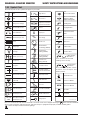
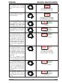
1.04 Symbol Chart
Note that only some of these symbols will appear on your model.
Gas Tungsten Arc
Welding (GTAW)
Air Carbon Arc
Cutting (CAC-A)
Constant Current
Constant Voltage
Or Constant Potential
High Temperature
Fault Indication
Arc Force
Touch Start (GTAW)
Variable Inductance
Voltage Input
Single Phase
Three Phase
Three Phase Static
Frequency Converter-
Transformer-Rectifier
Dangerous Voltage
Off
On
Panel/Local
Shielded Metal
Arc Welding (SMAW)
Gas Metal Arc
Welding (GMAW)
Increase/Decrease
Circuit Breaker
AC Auxiliary Power
Remote
Duty Cycle
Percentage
Amperage
Voltage
Hertz (cycles/sec)
Frequency
Negative
Positive
Direct Current (DC)
Protective Earth
(Ground)
Line
Line Connection
Auxiliary Power
Receptacle Rating-
Auxiliary Power
Art # A-04130_AB
115V 15A
t
t1
t2
%
X
IPM
MPM
t
V
Fuse
Wire Feed Function
Wire Feed Towards
Workpiece With
Output Voltage Off.
Preflow Time
Postflow Time
Spot Time
Spot Weld Mode
Continuous Weld
Mode
Press to initiate wirefeed and
welding, release to stop.
Purging Of Gas
Inches Per Minute
Meters Per Minute
Welding Gun
Burnback Time
Press and hold for preflow, release
to start arc. Press to stop arc, and
hold for preflow.
4 Step Trigger
Operation
2 Step Trigger
Operation
S
See Note
See Note
S
Note: For environments with increased hazard of electrical shock, Power Supplier bearing the mark conform to EN50192
when used in conjunction with hand torches with exposed tips, if equipped with properly installed standoff guides.
Cannot be disposed with household garbage.

SAFETY INSTRUCTIONS AND WARNINGS WELDSKILL 200AC/DC INVERTER
Manual 0-5206 1-7
Safety Instructions and Warnings
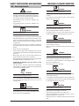
1.05 Servicing Hazards
!
WARNING
The symbols shown below are used throughout this
manual to call attention to and identify possible haz-
ards. When you see the symbol, watch out, and follow
the related instructions to avoid the hazard.
Only qualified persons should test, maintain, and
repair this unit.
Only qualified persons should test, maintain, and
repair this unit.
WARNING
ELECTRIC SHOCK can kill.
• Donottouchliveelectricalparts.
• TurnOffweldingpowersourceandwirefeederanddisconnect
and lockout input power using line disconnect switch, circuit
breakers, or by removing plug from receptacle, or stop engine
before servicing unless the procedure specifically requires an
energized unit.
• Insulateyourselffromground bystandingorworkingon
dry insulating mats big enough to prevent contact with the
ground.
• Donotleaveliveunitunattended.
• Ifthisprocedurerequiresandenergizedunit,haveonlyper-
sonnel familiar with and following standard safety practices
do the job.
• Whentestingaliveunit,usetheone-handmethod.Donot
put both hands inside unit. Keep one hand free.
• Disconnectinputpowerconductorsfromde-energizedsupply
line BEFORE moving a welding power source.
SIGNIFICANT DC VOLTAGE exists after removal of input
power on inverters.
• TurnOff inverters, disconnectinput power, and discharge
input capacitors according to instructions in Troubleshooting
Section before touching any parts.
WARNING
STATIC(ESD)candamagePCboards.
• PutongroundedwriststrapBEFOREhandlingboardsorparts.
• Useproperstatic-proofbagsandboxestostore,move,or
shipPCboards.
WARNING
FIREOREXPLOSIONhazard.
• Donotplaceuniton,over,ornearcombustiblesurfaces.
• Donotserviceunitnearammables.
WARNING
FLYINGMETALorDIRTcaninjureeyes.
• Wearsafetyglasseswithsideshieldsorfaceshieldduring
servicing.
• Becarefulnottoshortmetaltools,parts,orwirestogether
during testing and servicing.
WARNING
HOTPARTScancauseseverburns.
• Donottouchhotpartsbarehanded.
• Allowcoolingperiodbeforeworkingonequipment.
• To handle not parts, useproper toolsand/or wearheavy,
insulated welding gloves and clothing to prevent burns.
WARNING
EXPLODINGPARTScancauseinjury.
• Failedpartscanexplodeorcauseotherpartstoexplodewhen
power is applied to inverters.
• Alwayswearafaceshieldandlongsleeveswhenservicing
inverters.
WARNING
SHOCKHAZARDfromtesting.
• TurnOffweldingpowersourceandwirefeederorstopengine
before making or changing meter lead connections.
• Useatleastonemeterleadthathasaself-retainingspring
clip such as an alligator clip.
• Readinstructionsfortestequipment.
WARNING
FALLINGUNITcancauseinjury.
• Useliftingeyetoliftunitonly,NOTrunninggear,gascylinders,
or any other accessories.
• Useequipmentofadequatecapacitytoliftandsupportunit.
• Ifusingliftforkstomoveunit,besureforksarelongenough
toextendbeyondoppositesideofunit.
WARNING
MOVINGPARTScancauseinjury,
• Keepawayfrommovingpartssuchasfans.
• Keepawayfrompinchpointssuchasdriverolls.
• Haveonlyqualiedpersonsremovedoors,panels,covers,or
guards for maintenance as necessary.
• Keephands,hair,looseclothing,andtoolsawayfrommoving
parts.

Safety Instructions and Warnings
1-8 Manual 0-5206
WELDSKILL 200AC/DC INVERTER SAFETY INSTRUCTIONS AND WARNINGS
• Reinstalldoors,panels,covers,orguardswhenmaintenance
isnishedandbeforereconnectinginputpower.
WARNING
MAGNETIC FIELDS can affect Implanted Medical
Devices.
• WearersofPacemakersandotherImplantedMedicalDevices
shouldkeepawayfromservicingareasuntilconsultingtheir
doctorandthedevicemanufacturer.
WARNING
OVERUSEcancauseOVERHEATING.
• Allowcoolingperiod;followrateddutycycle.
• Reducecurrentorreducedutycyclebeforestartingtoweld
again.
• Donotblockorlterairowtounit.
WARNING
H.F.RADIATIONcancauseinterference.
• High-frequency(H.F.) can interfere with radio navigation,
safetyservices,computers,andcommunicationsequipment.
• Haveonlyqualiedpersonsfamiliarwithelectronicequipment
install,test,andserviceH.F.producingunits.
• Theuser is responsiblefor having a qualied electrician
promptly correct any interference problem resulting from
theinstallation.
• Ifnotied by the FCC about interference, stop using the
equipmentatonce.
• Havetheinstallationregularlycheckedandmaintained.
• Keephigh-frequencysourcedoorsandpanelstightlyshut,
keepsparkgapsatcorrectsetting,andusegroundingand
shieldingtominimizethepossibilityofinterference.
!
WARNING
READINSTRUCTIONS.
• UseTestingBooklet(PartNo.150853)whenservicingthis
unit.
• Consult theOwner’sManual forwelding safety precau-
tions.
• Use only genuine replacement partsfrom the manufac-
turer.
1.06 EMF Information
ConsiderationsAboutWeldingAndTheEffectsOfLowFrequency
Electric And Magnetic Fields
Weldingcurrent, as it owsthrough welding cables, will cause
electromagneticelds.Therehasbeenandstillissomeconcern
aboutsuchelds.However,afterexaminingmorethan500studies
spanning17 yearsof research, a specialblue ribboncommittee
of the National ResearchCouncil concluded that: “The bodyof
evidence, in the committee’sjudgment, has notdemonstrated
thatexposure to power-frequencyelectricandmagneticeldsis
ahuman-healthhazard.”However,studiesarestillgoingforthand
evidencecontinuestobeexamined.Untilthenalconclusionsof
theresearcharereached,youmaywishtominimizeyourexposure
toelectromagneticeldswhenweldingorcutting.
Toreduce magnetic elds in the workplace, use the following
procedures:
1. Keepcablesclosetogetherbytwistingortapingthem,orusing
acablecover.
2. Arrangecablestoonesideandawayfromtheoperator.
3. Donotcoilordrapecablesaroundyourbody.
4. Keepweldingpowersourceandcablesasfarawayfromoperator
aspractical.
5. Connectworkclamptoworkpieceasclosetotheweldaspos-
sible.
About Implanted Medical Devices:
Implanted Medical Device wearers should consulttheir doctor
andthedevicemanufacturerbeforeperformingorgoingneararc
welding,spotwelding,gouging,plasmaarccutting,orinduction
heatingoperations. If clearedby your doctor,thenfollowing the
aboveproceduresisrecommended.

INTRODUCTION WELDSKILL 200AC/DC INVERTER
Manual 0-5206 2-1
Introduction
SECTION 2:
INTRODUCTION
2.01 How to Use This Manual
To ensure safe operation, read the entire manual, includ-
ing the chapter on safety instructions and warnings.
Throughout this manual, the word WARNING, CAU-
TION and NOTE may appear. Pay particular attention to
the information provided under these headings. These
special annotations are easily recognized as follows:
!
WARNING
Gives information regarding possible per-
sonal injury. Warnings will be enclosed in a
box such as this.
CAUTION
Refers to possible equipment damage. Cau-
tions will be shown in bold type.
NOTE
Offers helpful information concerning certain
operating procedures. Notes will be shown
in italics
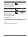
You will also notice icons from the safety section ap-
pearing throughout the manual. These are to advise you
of specific types of hazards or cautions related to the
portion of information that follows. Some may have
multiple hazards that apply and would look something
like this:
2.02 Equipment Identification
The unit’s identification number (specification or part
number), model, and serial number usually appear
on a nameplate attached to the machine. Equipment
which does not have a nameplate attached to the
machine is identified only by the specification or part
number printed on the shipping container. Record these
numbers for future reference.
2.03 Receipt of Equipment
When you receive the equipment, check it against the
invoice to make sure it is complete and inspect the
equipment for possible damage due to shipping. If there
is any damage, notify the carrier immediately to file a
claim. Furnish complete information concerning damage
claims or shipping errors to the location in your area
listed in the inside back cover of this manual. Include
all equipment identification numbers as described above
along with a full description of the parts in error.
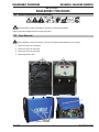
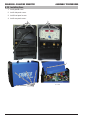
2.04 Description
The CIGWELD WELDSKILL 200AC/DC is a single phase
constant current welding inverter capable of performing
MMAW (Stick), GTAW (HF TIG) and GTAW (Lift TIG)
welding processes. The unit is equipped with digital
amperage and voltage meters, and a host of other fea-
tures in order to fully satisfy the broad operating needs
of the modern user. The unit is also fully compliant to
Australian Standard AS 60974.1 and IEC 60974.1.
The WELDSKILL 200AC/DC provides excellent welding
performance across a broad range of applications when
used with the correct welding consumables and proce-
dures. The following instructions detail how to correctly
and safely set up the machine and give guidelines on
gaining the best efficiency and quality from the Power
Source. Please read these instructions thoroughly be-
fore using the unit.
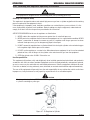
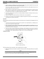
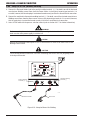
2.05 Transportation Methods
!
Disconnect input power
conductors from de-energized supply line before
moving the welding power source.
Lift unit with handle on top of case. Use handcart or
similar device of adequate capacity. If using a fork
lift vehicle, secure the unit on a proper skid before
transporting.

WELDSKILL 200AC/DC INVERTER INTRODUCTION
Introduction
2-2 Manual 0-5206
Notes

Manual 0-5206 3-1
Safety and Installation
SAFETY AND INSTALLATION WELDSKILL 200AC/DC INVERTER
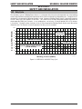
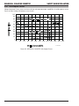
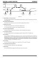
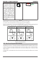
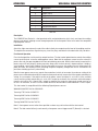
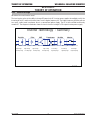
3.01 Duty Cycle
The rated duty cycle of a Welding Power Source, is a statement of the time it may be operated at its rated welding
current output without exceeding the temperature limits of the insulation of the component parts. To explain the 10
minute duty cycle period the following example is used. Suppose a Welding Power Source is designed to operate
at a 20% duty cycle, 200 amperes at 18.0 volts. This means that it has been designed and built to provide the
rated amperage (200A) for 2 minutes, i.e. arc welding time, out of every 10 minute period (20% of 10 minutes
is 2 minutes). During the other 8 minutes of the 10 minute period the Welding Power Source must idle and be
allowed to cool. The thermal cut out will operate if the duty cycle is exceeded.
10 20 30 40 50 60 70 80 90 100 110 120 130 140 150 160 170 180 190 200 210 220
WELDSKILL
200 AC/DC
Welding Current (AMPS)
SAFE OPERATING REGION
(TIG & STICK)
0
0
10
20
30
40
60
70
50
80
100
90
Duty Cycle (PERCENTAGE)
GTAW (TIG)
MMAW (STICK)
A-11218
Figure 3-1: WELDSKILL 200AC/DC Duty Cycle
SECTION 3:
SAFETY AND INSTALLATION

Safety and Installation
3-2 Manual 0-5206
WELDSKILL 200AC/DC INVERTER SAFETY AND INSTALLATION
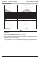
3.02 Specifications
Description WELDSKILL 200 AC/DC
Plant Part Number W1006200
Power Source Mass 22 kg
Power Source Dimensions H 400mm x W 240mm x D 475mm
Cooling Fan Cooled
Welder Type Inverter Power Source
Australian Standards AS 60974.1-2006 / IEC 60974-1
Number of Phases 1
Nominal Supply Voltage 240V +/- 15%
Nominal Supply Frequency 50/60Hz
Welding Current Range (STICK Mode) 5 – 200A
Effective Input Current (I1eff) (note1) 15A
Maximum Input Current (I1max) 38.8A
Single Phase Generator Requirement
(note2)
10kVA
STICK (MMAW)
Welding Output, 40ºC, 10 min.
170A @ 15%, 26.8V
100A @ 60%, 24.0V
80A @ 100%, 23.2V
TIG (GTAW)
Welding Output, 40ºC, 10 min.
200A @ 20%, 18.0V
116A @ 60%, 14.6V
90A @ 100%, 13.6V
Open circuit voltage (VRD inactive) 72V
Protection Class IP23S
Table 3-1: WELDSKILL 200AC/DC Specification
NOTE
Note 1: The Effective Input Current should be used for the determination of cable size & supply
requirements.
Note 2: Generator Requirements at the Maximum Output Duty Cycle.
Note 3: Motor start fuses or thermal circuit breakers are recommended for this application. Check local
requirements for your situation in this regard.
Due to variations that can occur in manufactured products, claimed performance, voltages, ratings, all
capacities, measurements, dimensions and weights quoted are approximate only. Achievable capacities
and ratings in use and operation will depend upon correct installation, use, applications, maintenance
and service.

Manual 0-5206 3-3
Safety and Installation
SAFETY AND INSTALLATION WELDSKILL 200AC/DC INVERTER
3.03 Environment
These units are designed for use in environments with increased hazard of electric shock as outlined in AS 60974.1
and AS 1674.2. Additional safety precautions may be required when using unit in an environment with increased
hazard of electric shock. Please refer to relevant local standards for further information prior to using in such areas.
A. In locations in which freedom of movement is restricted, so that the operator is forced to perform the work in
a cramped (kneeling, sitting or lying) position with physical contact with conductive parts.
B. In locations which are fully or partially limited by conductive elements, and in which there is a high risk of
unavoidable or accidental contact by the operator.
C. In wet or damp hot locations where humidity or perspiration considerably reduces the skin resistance of the
human body and the insulation properties of accessories.
Environments with increased hazard of electric shock do not include places where electrically conductive parts in
the near vicinity of the operator, which can cause increased hazard, have been insulated.
3.04 Location
Be sure to locate the welder according to the following guidelines:
• Inareas,freefrommoistureanddust.
• Ambienttemperaturebetween-10°Cto40°C(14°Fto104°F).
• Inareas,freefromoil,steamandcorrosivegases.
• Inareas,notsubjectedtoabnormalvibrationorshock.
• Inareas,notexposedtodirectsunlightorrain.
• Placeatadistanceof300mm(12”)ormorefromwallsorsimilarthatcouldrestrictnaturalairowfor
cooling
• TheenclosuredesignofthispowersourcemeetstherequirementsofIP23SasoutlinedinAS60529.This
providesadequateprotectionagainstsolidobjects(greaterthan12mm),anddirectprotectionfromvertical
drops. Under no circumstances should the unit be operated or connected in a micro environment that will
exceed the stated conditions. For further information please refer to AS 60529.
• Precautionsmustbetakenagainstthepowersourcetopplingover.Thepowersourcemustbelocatedon
a suitable horizontal surface in the upright position when in use.
!
WARNING
Thermal Arc advises that this equipment be electrically connected by a qualified electrician.
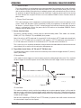
3.05 High Frequency Introduction
The importance of correct installation of high frequency welding equipment cannot be overemphasized. Interference
due to high frequency initiated or stabilised arc is almost invariably traced to improper installation. The following
information is intended as a guide for personnel installing high frequency welding machines.
!
WARNING EXPLOSIVES
The high frequency section of this machine has an output similar to a radio transmitter. The machine
should NOT be used in the vicinity of blasting operations due to the danger of premature firing

Safety and Installation
3-4 Manual 0-5206
WELDSKILL 200AC/DC INVERTER SAFETY AND INSTALLATION
!
WARNING COMPUTER
It is also possible that operation close to
computer installations may cause computer
malfunction.
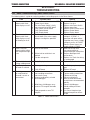
3.06 High Frequency Interference
Interference may be transmitted by a high frequency
initiated or stabilised arc welding machine in the
following ways.
1. Direct Radiation: Radiation from the machine can
occur if the case is metal and is not properly grounded.
It can occur through apertures such as open access
panels. The shielding of the high frequency unit in
the Power Source will prevent direct radiation if the
equipment is properly grounded.
2. Transmission via the Supply Lead: Without
adequate shielding and filtering, high frequency energy
may be fed to the wiring within the installation (mains)
by direct coupling. The energy is then transmitted by
both radiation and conduction. Adequate shielding and
filtering is provided in the Power Source.
3. Radiation from Welding Leads: Radiated interference
from welding leads, although pronounced in the vicinity
of the leads, diminishes rapidly with distance. Keeping
leads as short as possible will minimise this type of
interference. Looping and suspending of leads should
be avoided wherever possible.
4. Re-Radiation from Unearthed Metallic Objects: A
majorfactorcontributingtointerferenceisre-radiation
fromunearthedmetallicobjectsclosetothewelding
leads.Effectivegroundingofsuchobjectswillprevent
re-radiation in most cases.
3.07 Electromagnetic Compatibility
WARNING
Extra precautions for Electromagnetic
Compatibility may be required when this
Welding Power Source is used in a domestic
situation.
A. Installation and Use - Users Responsibility
The user is responsible for installing and using the
welding equipment according to the manufacturer’s
instructions. If electromagnetic disturbances are
detected then it shall be the responsibility of the user
of the welding equipment to resolve the situation with
the technical assistance of the manufacturer. In some
cases this remedial action may be as simple as earthing
the welding circuit, see NOTE below. In other cases it
could involve constructing an electromagnetic screen
enclosing the Welding Power Source and the work,
complete with associated input filters. In all cases,
electromagnetic disturbances shall be reduced to the
point where they are no longer Trouble-some.
NOTE
The welding circuit may or may not be
earthed for safety reasons. Changing the
earthing arrangements should only be
authorised by a person who is competent to
assess whether the changes will increase the
riskofinjury,e.g.byallowingparallelwelding
current return paths which may damage the
earth circuits of other equipment. Further
guidance is given in IEC 974-13 Arc Welding
Equipment - Installation and use (under
preparation).
B. Assessment of Area
Before installing welding equipment, the user shall make
an assessment of potential electromagnetic problems
in the surrounding area. The following shall be taken
into account.
1. Other supply cables, control cables, signaling and
telephonecables;above,belowandadjacenttothe
welding equipment.
2. Radio and television transmitters and receivers.
3. Computer and other control equipment.
4. Safety critical equipment, e.g. guarding of industrial
equipment.
5. The health of people around, e.g. the use of pace-
makers and hearing aids.
6. Equipment used for calibration and measurement.
7. The time of day that welding or other activities are
to be carried out.
8. The immunity of other equipment in the environment:
the user shall ensure that other equipment being
used in the environment is compatible: this may
require additional protection measures.
The size of the surrounding area to be considered
will depend on the structure of the building and other
activities that are taking place. The surrounding area
may extend beyond the boundaries of the premises.
Page is loading ...
Page is loading ...
Page is loading ...
Page is loading ...
Page is loading ...
Page is loading ...
Page is loading ...
Page is loading ...
Page is loading ...
Page is loading ...
Page is loading ...
Page is loading ...
Page is loading ...
Page is loading ...
Page is loading ...
Page is loading ...
Page is loading ...
Page is loading ...
Page is loading ...
Page is loading ...
Page is loading ...
Page is loading ...
Page is loading ...
Page is loading ...
Page is loading ...
Page is loading ...
Page is loading ...
Page is loading ...
Page is loading ...
Page is loading ...
Page is loading ...
Page is loading ...
Page is loading ...
Page is loading ...
Page is loading ...
Page is loading ...
Page is loading ...
Page is loading ...
Page is loading ...
Page is loading ...
Page is loading ...
Page is loading ...
Page is loading ...
Page is loading ...
Page is loading ...
Page is loading ...
Page is loading ...
Page is loading ...
Page is loading ...
Page is loading ...
Page is loading ...
Page is loading ...
Page is loading ...
Page is loading ...
Page is loading ...
Page is loading ...
Page is loading ...
Page is loading ...
Page is loading ...
Page is loading ...
Page is loading ...
Page is loading ...
Page is loading ...
Page is loading ...
Page is loading ...
Page is loading ...
Page is loading ...
Page is loading ...
-
 1
1
-
 2
2
-
 3
3
-
 4
4
-
 5
5
-
 6
6
-
 7
7
-
 8
8
-
 9
9
-
 10
10
-
 11
11
-
 12
12
-
 13
13
-
 14
14
-
 15
15
-
 16
16
-
 17
17
-
 18
18
-
 19
19
-
 20
20
-
 21
21
-
 22
22
-
 23
23
-
 24
24
-
 25
25
-
 26
26
-
 27
27
-
 28
28
-
 29
29
-
 30
30
-
 31
31
-
 32
32
-
 33
33
-
 34
34
-
 35
35
-
 36
36
-
 37
37
-
 38
38
-
 39
39
-
 40
40
-
 41
41
-
 42
42
-
 43
43
-
 44
44
-
 45
45
-
 46
46
-
 47
47
-
 48
48
-
 49
49
-
 50
50
-
 51
51
-
 52
52
-
 53
53
-
 54
54
-
 55
55
-
 56
56
-
 57
57
-
 58
58
-
 59
59
-
 60
60
-
 61
61
-
 62
62
-
 63
63
-
 64
64
-
 65
65
-
 66
66
-
 67
67
-
 68
68
-
 69
69
-
 70
70
-
 71
71
-
 72
72
-
 73
73
-
 74
74
-
 75
75
-
 76
76
-
 77
77
-
 78
78
-
 79
79
-
 80
80
-
 81
81
-
 82
82
-
 83
83
-
 84
84
-
 85
85
-
 86
86
-
 87
87
-
 88
88


ESAB 300Pi Transtig Welding Inverter User manual
- Category
- Welding System
- Type
- User manual
Ask a question and I''ll find the answer in the document
Finding information in a document is now easier with AI
Related papers
-
ESAB 200AC/DC Inverter Arc Welding Machine User manual
-
-
-
-
-
-
-
-
-
Other documents
-
Sunnydaze Decor JH-553 Installation guide
-
CIGWELD WeldSkill 205ACDC Operating instructions
-
CIGWELD WeldSkill 155 Operating instructions
-
-
-
 METAL MAN 200iDV ACDC Specification
-
 Svarog ARC 160-PFC User manual
-
Crossfire DIGITIG 200 Owner's manual
-
 Strata ADVANCETIG 200 Operating Instructions Manual
-
 Thermal Arc 186 DC Setup Manual


