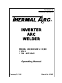
ESAB Inverter Arc Welder Model 130/150/190 S CC/DC User manual
- Category
- Welding System
- Type
- User manual
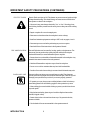
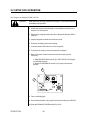
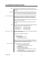
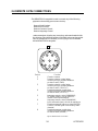
ESAB Inverter Arc Welder Model 130/150/190 S CC/DC is an inverter-based, portable arc welder designed for stick and lift start TIG applications. It offers a range of welding capabilities, including stick welding with electrodes up to 1/4 inch, and TIG welding with a maximum output of 190 amps. The welder is equipped with a digital display that provides precise control over welding parameters, including amperage and voltage. Additionally, it features advanced inverter technology that delivers a stable and consistent arc, ensuring high-quality welds.
ESAB Inverter Arc Welder Model 130/150/190 S CC/DC is an inverter-based, portable arc welder designed for stick and lift start TIG applications. It offers a range of welding capabilities, including stick welding with electrodes up to 1/4 inch, and TIG welding with a maximum output of 190 amps. The welder is equipped with a digital display that provides precise control over welding parameters, including amperage and voltage. Additionally, it features advanced inverter technology that delivers a stable and consistent arc, ensuring high-quality welds.


-
 1
1
-
 2
2
-
 3
3
-
 4
4
-
 5
5
-
 6
6
-
 7
7
-
 8
8
-
 9
9
-
 10
10
-
 11
11
-
 12
12
-
 13
13
-
 14
14
-
 15
15
-
 16
16
-
 17
17
-
 18
18
-
 19
19
-
 20
20
-
 21
21
-
 22
22
-
 23
23
-
 24
24
-
 25
25
-
 26
26


ESAB Inverter Arc Welder Model 130/150/190 S CC/DC User manual
- Category
- Welding System
- Type
- User manual
ESAB Inverter Arc Welder Model 130/150/190 S CC/DC is an inverter-based, portable arc welder designed for stick and lift start TIG applications. It offers a range of welding capabilities, including stick welding with electrodes up to 1/4 inch, and TIG welding with a maximum output of 190 amps. The welder is equipped with a digital display that provides precise control over welding parameters, including amperage and voltage. Additionally, it features advanced inverter technology that delivers a stable and consistent arc, ensuring high-quality welds.
Ask a question and I''ll find the answer in the document
Finding information in a document is now easier with AI
Related papers
-
ESAB SL60 SL100 1Torch Plasma Cutting Torch User manual
-
-
-
ESAB Plasma Cutting System Model Drag-Gun Plus with Built-In Air Compressor User manual
-
-
-
-
ESAB 320SP 400SP 500SP Powermaster User manual
-
-
Other documents
-
Grizzly G0880 Owner's manual
-
 Thermal Arc POWERMASTER 500SP User manual
-
Miller QUICK CUT 3800 Owner's manual
-
-
-
 Thermal Arc Raider 10 Owner's manual
-
 Thermal Dynamics 38 Cutmaster Operating instructions
-
 Thermal Dynamics CUTSKILL C-100A Operating instructions
-
 Thermal Dynamics 42 CUTMASTER Operating instructions
-
 Thermal Dynamics Pak Master 50 User manual


