Page is loading ...

InnovaMass
®
240/241 HART
Instruction Manual
HART Device Specification for Models:
240-V, -VT, -VTP, -LP & 241-V, -VT, -VTP, -LP
Multivariable Mass Vortex Flow Meters
Part Number: IM240/241 Modbus, Rev. V1
May 2013

GLOBAL SUPPORT LOCATIONS: WE ARE HERE TO HELP!
CORPORATE HEADQUARTERS
5 Harris Court, Building L Monterey, CA 93940
Phone (831) 373-0200 (800) 866-0200 Fax (831) 373-4402
www.sierrainstruments.com
EUROPE HEADQUARTERS
Bijlmansweid 2 1934RE Egmond aan den Hoef
The Netherlands
Phone +31 72 5071400 Fax +31 72 5071401
ASIA HEADQUARTERS
Second Floor Building 5, Senpu Industrial Park
25 Hangdu Road Hangtou Town
Pu Dong New District, Shanghai, P.R. China
Postal Code 201316
Phone: + 8621 5879 8521 Fax: +8621 5879 8586
IMPORTANT CUSTOMER NOTICE- OXYGEN SERVICE
Sierra Instruments, Inc. is not liable for any damage or personal injury, whatsoever, resulting from the use of Sierra Instruments
standard mass flow meters for oxygen gas. You are responsible for determining if this mass flow meter is appropriate for your
oxygen application. You are responsible for cleaning the mass flow meter to the degree required for your oxygen flow
application.
© COPYRIGHT SIERRA INSTRUMENTS 2012
No part of this publication may be copied or distributed, transmitted, transcribed, stored in a retrieval system, or translated
into any human or computer language, in any form or by any means, electronic, mechanical, manual, or otherwise, or
disclosed to third parties without the express written permission of Sierra Instruments. The information contained in this
manual is subject to change without notice.
TRADEMARKS
InnovaFlo
®
and InnovaMass
®
are trademarks of Sierra Instruments, Inc. Other product and company names listed in this
manual are trademarks or trade names of their respective manufacturers.

Warnings and Cautions
Warning!
Agency approval for hazardous location installations varies between flow meter models. Consult the flow meter
nameplate for specific flow meter approvals before any hazardous location installation.
Warning!
Hot tapping must be performed by a trained professional. U.S. regulations often require a hot tap permit. The
manufacturer of the hot tap equipment and/or the contractor performing the hot tap is responsible for providing proof of such a
permit.
Warning!
All wiring procedures must be performed with the power off.
Warning!
To avoid potential electric shock, follow National Electric Code safety practices or your local code when wiring this unit
to a power source and to peripheral devices. Failure to do so could result in injury or death. All AC power connections must be in
accordance with published CE directives.
Warning!
Do not power the flow meter with the sensor remote (if applicable) wires disconnected. This could cause over-heating of the
sensors and/or damage to the electronics.
Warning!
Before attempting any flow meter repair, verify that the line is de-pressurized.
Warning!
Always remove main power before disassembling any part of the mass flow meter.
Caution!
Before making adjustments to the device, verify the flow meter is not actively monitoring or reporting to any master
control system. Adjustments to the electronics will cause direct changes to flow control settings.
Caution!
All flow meter connections, isolation valves and fittings for hot tapping must have the same or higher pressure rating
as the main pipeline.
Caution!
Changing the length of cables or interchanging sensors or sensor wiring will affect the accuracy of the flow meter.
You cannot add or subtract wire length without returning the meter to the factory for re-calibration.
Caution!
When using toxic or corrosive gases, purge the line with inert gas for a minimum of four hours at full gas flow
before installing the meter.
Caution!
The AC wire insulation temperature rating must meet or exceed 80°C (176°F).
Caution!
Printed circuit boards are sensitive to electrostatic discharge. To avoid damaging the board, follow these
precautions to minimize the risk of damage:
before handling the assembly, discharge your body by touching a grounded, metal object
handle all cards by their edges unless otherwise required
when possible, use grounded electrostatic discharge wrist straps when handling sensitive components
!

4
Note and Safety Information
We use caution and warning statements throughout this book to draw
your attention to important
information.
Warning!
Caution!
This statement appears with information that
is important to protect people and equipment
from damage. Pay very close attention to all
warnings that apply to your application.
This statement appears with information that is
important for protecting your equipment and
performance. Read and follow all cautions that
apply to your application.
Receipt of System Components
When receiving a Sierra mass flow meter, carefully check the outside
packing
carton for damage
incurred in shipment. If the carton is damaged, notify the local carrier and submit a report to the
factory or distributor. Remove the packing slip and check that all ordered components are present.
Make sure any spare parts or accessories are not
discarded with the packing material. Do not
return any equipment to
the factory without first contacting Sierra Customer Service
.
Technical Assistance
If you encounter a problem with your flow meter, review the configuration information for each
step of the installation, operation, and
setup procedures. Verify that your settings and adjustments
are consistent with factory recommendations. Installation and troubleshooting information can be
found in the 240/241 Series Product Instruction Manual.
If the problem persists after following the troubleshooting procedures
outlined in the 640S or 780S
product manuals, contact Sierra Instruments by fax or by E-mail
(see inside front cover). For
urgent phone support you may call (800)
866-0200 or (831) 373-0200 between 8:00 a.m. and 5:00
p.m. PST. In
Europe, contact Sierra Instruments Europe at +31 20 6145810. In the Asia-Pacific
region, contact Sierra Instruments Asia at +
86-21-58798521.
When contacting Technical Support,
make sure to include this information:
The flow range, serial number, and Sierra order number (all
marked on the meter
nameplate)
The software version (visible at start up)
The problem you are encountering and any corrective action
taken
Application information (gas, pressure, temperature and piping
configuration)
!

5
Table of Contents
Table of Contents ............................................................................................................................ 5
Chapter 1: HART Communications ................................................................................................ 6
Loop Powered Meter Wiring .......................................................................... Error! Bookmark not defined.
DC Powered Meter Wiring ............................................................................................................................ 7
AC Powered Meter Wiring ............................................................................. Error! Bookmark not defined.
Multi-Point Meter Wiring ................................................................................. Error! Bookmark not defined.
Chapter 2: HART Commands with the DD Menu .......................................................................... 9
HART Commands with Generic DD Menu…………………………………………………………………….....14
Fast Key Sequence………………………………………………………………………………………………….15

6
Chapter 1: HART Communications
The HART Communications Protocol (Highway Addressable Remote Transducer Protocol) is a bidirectional
digital serial communications protocol. The HART signal is based on the Bell 202 standard and is
superimposed on 4-20 mA Output 1. Burst mode is not supported.
Wiring
The diagrams below detail the proper connections required for HART
communications:
Warning!
Place controls in manual
mode when making
configuration changes to
the instrument.

7
Loop Powered Meter Wiring, HART Point-to-Point, Shown Below
LOOP
POWER
+ -
FREQ
OUT
PULSE
OUT
-- + +
OPTIONAL
BACKLIGHT
POWER
+ -
R load,
250 ohm
minimum
+
_
DC
Power
Supply
Remote Connection
for Communicator
Current
Meter
Field Connection
for Communicator
Vortex Meter
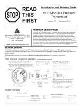
DC Powered Meter Wiring, Shown Below
R load,
250 ohm
minimum
+
_
DC
Power
Supply
Remote Connection
for Communicator
Field Connection
for Communicator
Current
Meter
Vortex Meter
4-20
mA 3
4-20
mA 1
DC PWR
+ - +
4-20
mA 2
- + - +
RS485
RS485
RS485 GND
-
OPTION 2
+
ALARM
2
PULSE
OUT
FREQ
OUT
+ - +
ALARM
1
-+ -
4
OPTION 1
1 2 3 15 2 3
ALARM
3
- + -
4 5
+
-

8
AC Powered Meter Wiring, HART Point-to-Point, Shown Below
R load,
250 ohm
minimum
Remote Connection
for Communicator
Field Connection
for Communicator
Current
Meter
Vortex Meter
4-20
mA 3
AC
PWR
IN
4-20
mA 1
24
VDC
OUT
+ - +
4-20
mA 2
- + - +
RS485
RS485
RS485 GND
-
OPTION 2
+
ALARM
2
HOT
PULSE
OUT
NEUT
FREQ
OUT
+ - +
ALARM
1
-+ -
4
OPTION 1
1 2 3 15 2 3
ALARM
3
- + -
4 5
+
-
Multi-Point Meter Wiring (digital only) Loop Power, Shown Below
Note: To activate Multi-drop mode, put a device ID of 1 to 15 in the “Dev id” menu (0 is point to point mode).
This fixes the 4-20 mA output to 4 mA. Typically DC power for the loop is provided by an external power
supply (isolated power on AC and DC models). Consult your HART modem manufactures documentation for
specific wiring requirements.

9
Chapter 2: HART Commands with the InnovaMass DD Menu
Available on HARTcomm.org under INNOVAMASS
Online Menu
1 Device Setup
2 Process Variables
3 PV is
4 PV
5 AO1 Out
6 PV % rnge
7 Alrm Status
8 Diagnostics
9 Calibration Review
1 Display Unit
2 Analog Output
3 External Loop
4 Meter Display
5 Alarm Setup
6 Totalizer
7 Fluid Menu
8 Energy Setup
9 Device Menu
Diagnostics
Sensor Cal
Review
1 Mass flo unit
2 Vol unit
3 Temp unit
4 Energy flo unit
5 Line press unit
6 Dens unit
7 Totalizer units
8 Std & Norm Cond
1 Disp Cycle
2 Disp Digits
3 Disp Damping
4 Init Displ.
5 Disp Show/Hide
1 Alarm Status
2 Alarm 1 Setup
3 Alarm 2 Setup
4 Alarm 3 Setup
5 Records in Log
6 Read Alarm Log
7 Alarm Log Clear
1 Total
2 Totalize
3 Amount/Pulse
4 Total 2
5 Totalize 2
6 Clear Totalizer
1 Mass Flo
2 Vol
3 Temp
4 Temp 2
5 Delta Temp.
6 Energy flo
7 Press
8 Dens
9 Totl
Total 2
1 K Factor
2 Ck Value
3 Lo Flo Cutoff
4 RTD1 Ro
5 RTD1 alpha
6 RTD1 beta
7 RTD2 Ro
8 RTD2 alpha
9 RTD2 beta
Pcal B00, Pcal B01
Pcal B02, Pcal B10
Pcal B11, Pcal B12
Pcal B20, Pcal B21
Pcal B22
Ref. Resistance
Internal Temp. Cal
Cal current
Flow 1
Deviation 1
Flow 2
Deviation 2
Flow 3
Deviation 3
Flow 4
Deviation 4
Flow 5
Deviation 5
Flow 6
Deviation 6
Flow 7
Deviation 7
Flow 8
Deviation 8
Flow 9
Deviation 9
Flow 10
Deviation 10
1 Alrm 1 var
2 Alrm 1 typ
3 Alrm 1 set pt
1 Alrm 2 var
2 Alrm 2 typ
3 Alrm 2 set pt
1 Alrm 3 var
2 Alrm 3 typ
3 Alrm 3 set pt
1 Norm Temp
2 Norm Press
3 Std Temp
4 Std Press
To Analog Output Menu
To Fluid Menu
From Sensor Cal Menu,
Calibration Review
1 External Input
2 Set Ext. 4 mA
3 Set Ext. 20 mA
Inactive
Temp1
Temp 2
Pressure
1 Meter Location
2 Heating or Cooling
3 % Return
To Diagnostics Menu
To Sensor Cal Menu
To Review Menu
To Diagnostics Menu
1 Date
2 h
3 min
4 s
5 Password
6 Meter Size
7 Dev id
8 Tag
9 Descriptor
Message
Final assy num
Poll adr
Num req preams
Config Code
Compile Date
Compile Time
Signal Board Version
Hardware rev
Software rev
Master reset

10
1 Fix Analog Output
2 Trim Analog Output
3 Configure AO1
4 PV is
5 PV AO1 Out
6 PV % rnge
7 Configure AO2
8 SV is
9 SV AO2 Out
SV % rnge
Configure AO3
TV is
TV AO
TV % rnge
Configure AO4
QV is
QV AO
QV % rnge
1 PV is
2 PV AO1 Out
3 PV
4 PV % rnge
5 Apply values
6 PV Rnge unit
7 PV LRV
8 PV URV
9 PV AO1 Lo end pt
PV AO1 Hi end pt
PV AO1 Added damp
1 SV is
2 SV AO2 Out
3 SV
4 SV % rnge
5 Apply values
6 SV Rnge unit
7 SV LRV
8 SV URV
9 SV AO2 Lo end pt
SV AO2 Hi end pt
SV AO2 Added damp
1 TV is
2 TV AO
3 TV
4 TV % rnge
5 Apply values
6 TV Rnge unit
7 TV LRV
8 TV URV
9 TV AO3 Lo end pt
TV AO3 Hi end pt
TV AO3 Added damp
1 QV is
2 QV AO
3 QV
4 QV % rnge
5 Apply values
6 QV Rnge unit
7 QV LRV
8 QV URV
9 QV AO1 Lo end pt
QV AO1 Hi end pt
QV AO1 Added damp
From Online Menu
Analog Output Menu

11
1 Fluid
2 Fluid Type
Water
Ammonia
Chlorine
From Online Menu
Fluid Menu
Liquid
Other Liquid
Goyal-Dorais
API-2540
Nat Gas AGA8
Real Gas
Other Gas
Liquified Gas
Other Liquid Density
Viscosity Coef AL
Viscosity Coef BL
Mol Weight
Crit Press
Crit Temp
Compressibility
AL
BL
Density @ 60F
API K0
API K1
API AL
API BL
AGA Ref Temp
AGA Ref Press
Specific Gravity
Mole Fract N2
Mole Fract CO2
Steam
Air
Argon
Ammonia
CO
CO2
Helium
Hydrogen
Methane
Nitrogen
Oxygen
Propane
Specific gravity
Compress
Viscosity
Carbon Dioxide
Nitrogen
Hydrogen
Oxygen
Argon
Nitrous Oxide

12
1 Vortex Diag
2 Press Diag
3 Temp Diag
4 Vel
5 Temp
6 Temp 2
7 Press
8 Records in Log
9 Read System Log
System Log Clear
Status
1 Vtx Freq
2 Sim Vtx Freq
3 Vtx AtoD
4 Filter Set
5 Gain Set
6 Re
7 Vel
8 Max Vel
9 AD1
AD2
AD3
AD4
1 Press
2 Sim Press
3 Excite
4 Excite AtoD
5 Sense
6 Sense AtoD
7 Max Press
1 Temp
2 Sim Temp
3 RTD1
4 RTD1 AtoD
5 Max temp
6 Temp 2
7 Sim Temp 2
8 RTD2
9 RTD2 AtoD
Max temp 2
From Online Menu
Diagnostics Menu
1 Status group 1
2 Status group 2
3 Status group 3
SPI not communicating
Freq. Input Overrange
FRAM CRC error
Signal Board Power ...
RTD1 Fault
RTD2 Fault
Press. Transducer Fault
Totalizer Relay Overrange
Alarm 1 Set
Alarm 2 Set
Alarm 3 Set
1 Model
2 Distributor
3 Write protect
4 Manufacturer
5 Dev id
6 Tag
7 Descriptor
8 Message
9 Date
Final asmbly num
Universal rev
Fld dev rev
Software rev
Burst mode
Burst option
Poll addr
Num req preams
From Online Menu
Review Menu

13
1 Calibration Review
2 Vortex Sensor
3 Vortex Cal
4 Press Sensor
5 Press Cal
6 Temp Sensor
7 Temp 1 & 2 Cal
8 Temp 2 Sensor
9 Cal. Correction
1 Vol snsr unit
2 USL
3 LSL
4 Min Span
5 Damp
6 Snsr s/n
7 Sim Vtx
8 Max Vel
9 Vortex Diag
1 K Factor
2 Ck Value
3 Lo flo cutoff
1 Pres snsr unit
2 USL
3 LSL
4 Min span
5 Damp
6 Snsr s/n
7 Sim Press
8 Maximum
9 Press Diag
1 PCal B00
2 PCal B01
3 PCal B02
4 PCal B10
5 PCal B11
6 PCal B12
7 PCal B20
8 PCal B21
9 PCal B22
Ref. Resistance
Internal Temp. Cal
Cal Current
1 Temp unit
2 USL
3 LSL
4 Min span
5 Damp
6 Snsr s/n
7 Sim Temp
8 Maximum
9 Temp Diag
1 RTD1 Ro
2 RTD1 alpha
3 RTD1 beta
4 RTD2 Ro
5 RTD2 alpha
6 RTD2 beta
1 Vtx Freq
2 Sim Vtx Freq
3 Vtx AtoD
4 Filter Set
5 Gain Set
6 Re
7 Vel
8 Max Vel
9 AD1
AD2
AD3
AD4
1 Press
2 Sim Press
3 Excite
4 Excite AtoD
5 Sense
6 Sense AtoD
7 Max Press
1 Temp
2 Sim Temp
3 RTD1
4 RTD1 AtoD
5 Max Temp
6 Temp 2
7 Sim Temp 2
8 RTD2
9 RTD2 AtoD
Max temp 2
From Online Menu
To Calibration Review Menu
1 Temp unit
2 USL
3 LSL
4 Min span
5 Damp
6 Snsr s/n
7 Sim Temp 2
8 Maximum
9 Temp Diag
1 Temp
2 Sim Temp
3 RTD1
4 RTD1 AtoD
5 Max Temp
6 Temp 2
7 Sim Temp 2
8 RTD2
9 RTD2 AtoD
Max temp 2
Sensor Cal Menu
1 Flow 1
2 Deviation 1
3 Flow 2
4 Deviation 2
5 Flow 3
6 Deviation 3
7 Flow 4
8 Deviation 4
9 Flow 5
Deviation 5
Flow 6
Deviation 6
Flow 7
Deviation 7
Flow 8
Deviation 8
Flow 9
Deviation 9
Flow 10
Deviation 10
Figure 1 Sensor Cal Menu

14
HART Commands with Generic DD Menu
Online Menu
1 Device Setup
2 PV
3 PV AO
4 PV LRV
5 URV
1 Process Variables
2 Diag/Service
3 Basic Setup
4 Detailed Setup
5 Review
1 Snsr
2 AI % Rnge
3 AO1
1 Distributor
2 Model
3 Dev id
4 Tag
5 Date
6 Write Protect
7 Descriptor
8 Message
9 PV snsr s/n
Final assy #
Revision #'s
1 Test Device
2 Loop Test
3 Calibration
4 D/A Trim
1 Tag
2 PV unit
3 Range Values
4 Device Information
5 PV Xfer fnctn
6 PV Damp
1 PV LRV
2 PV URV
3 PV LSL
4 PV USL
1 Universal Rev
2 Fld dev Rev
3 Software Rev
1 4 mA
2 20 mA
3 Other
4 End
1 Apply Values
2 Enter Values
1 4 mA
2 20 mA
3 Exit
1 PV LRV
2 PV URV
3 PV USL
4 PV LSL
1 Sensors
2 Signal Condition
3 Output Condition
4 Device Information
1 PV
2 PV Sensor Unit
3 Sensor information
1 Snsr Damp
2 URV
3 AI LRV
4 Xfer Fnctn
5 AI % rnge
1 Analog Output
2 HART Output
1 Distributor
2 Model
3 Dev id
4 Tag
5 Date
6 Write Protect
7 Descriptor
8 Message
9 PV snsr s/n
Final assy #
Revision #'s
1 AO1
2 AO alarm typ
3 Loop test
4 D/A trim
5 Scaled D/A trim
1 4 mA
2 20 mA
3 Other
4 End
1 Poll addr
2 Num req. preams
3 Burst mode
4 Burst option
1 Universal Rev
2 Fld dev Rev
3 Software Rev
1 PV LRV
2 PV URV
PV LSL, PV USL, PV Min span
1 PV LRV
2 PV URV
Figure 2 Online Menu -use Password 16363.

15
Fast Key Sequence
Use password 16363.
Sequence
Description
Access
Notes
1,1,1
Snsr
View
Primary variable value
1,1,2
AI % Rnge
View
Analog output % range
1,1,3
AO1
View
Analog output, mA
1,2,1
Test Device
N/A
Not used
1,2,2,1
4 mA
View
Loop test, fix analog output at 4 mA
1,2,2,2
20 mA
View
Loop test, fix analog output at 20 mA
1,2,2,3
Other
Edit
Loop test, fix analog output at mA value entered
1,2,2,4
End
Exit loop test
1,2,3,1,1
4 mA
N/A
Not used, apply values
1,2,3,1,2
20 mA
N/A
Not used, apply values
1,2,3,1,3
Exit
Exit apply values
1,2,3,2,1
PV LRV
Edit
Primary variable lower range value
1,2,3,2,2
PV URV
Edit
Primary variable upper range value
1,2,3,2,3
PV USL
View
Primary variable upper sensor limit
1,2,3,2,4
PV LSL
View
Primary variable lower sensor limit
1,2,4
D/A Trim
Edit
Calibrate electronics 4mA and 20mAvalues
1,3,1
Tag
Edit
Tag
1,3,2
PV unit
Edit
Primary variable units
1,3,3,1
PV LRV
Edit
Primary variable lower range value
1,3,3,2
PV URV
Edit
Primary variable upper range value
1,3,3,3
PV LSL
View
Primary variable upper sensor limit
1,3,3,4
PV USL
View
Primary variable lower sensor limit
1,3,4,1
Distributor
N/A
Not used
1,3,4,2
Model
N/A
Not used
1,3,4,3
Dev id
View
Device identification
1,3,4,4
Tag
Edit
Tag
1,3,4,5
Date
Edit
Date
1,3,4,6
Write Protect
View
Write protect
1,3,4,7
Descriptor
Edit
Vortex flowmeter
1,3,4,8
Message
Edit
32 character alphanumeric message
1,3,4,9
PV snsr s/n
View
Primary variable sensor serial number
1,3,4,men
u
Final assy #
Edit
Final assembly number
1,3,4,men
u,1
Universal Rev
View
Universal revision
1,3,4,men
u,2
Fld dev Rev
View
Field device revision
1,3,4,men
u,3
Software Rev
View
Software revision
1,3,5
PV Xfer fnctn
View
Linear
1,3,6
PV Damp
Edit
Primary variable damping (time constant) in
seconds
1,4,1,1
PV
View
Primary variable value
1,4,1,2
PV Sensor Unit
Edit
Primary variable units
1,4,1,3
Sensor
Information
View
PV LSL, PV USL, PV Min span
1,4,2,1
Snsr Damp
Edit
Primary variable damping (time constant) in
seconds
1,4,2,2,1
PV LRV
Edit
Primary variable low range value
1,4,2,2,2
PV URV
Edit
Primary variable upper range value
1,4,2,3,1
PV LRV
Edit
Primary variable low range value
1,4,2,3,2
PV URV
Edit
Primary variable upper range value
1,4,2,4
Xfer Fnctn
View
Linear
1,4,2,5
AI % rnge
View
Analog output % range
1,4,3,1,1
AO1
View
Analog output, mA
1,4,3,1,2
AO alarm typ
N/A
Not used

16
Sequence
Description
Access
Notes
1,4,3,1,3,1
4 mA
View
Loop test, fix analog output at 4 mA
1,4,3,1,3,2
20 mA
View
Loop test, fix analog output at 20 mA
1,4,3,1,3,3
Other
Edit
Loop test, fix analog output at mA value entered
1,4,3,1,3,4
End
Exit loop test
1,4,3,1,4
D/A trim
Edit
Calibrate electronics 4mA and 20mAvalues
1,4,3,1,5
Scaled D/A trim
N/A
Not used
1,4,3,2,1
Poll addr
Edit
Poll address
1,4,3,2,2
Num req.
preams
View
Number of required preambles
1,4,3,2,3
Burst mode
N/A
Not used
1,4,3,2,4
Burst option
N/A
Not used
1,4,4,1
Distributor
N/A
Not used
1,4,4,2
Model
N/A
Not used
1,4,4,3
Dev id
View
Device identification
1,4,4,4
Tag
Edit
Tag
1,4,4,5
Date
Edit
Date
1,4,4,6
Write Protect
View
Write protect
1,4,4,7
Descriptor
Edit
Vortex flowmeter
1,4,4,8
Message
Edit
32 character alphanumeric message
1,4,4,9
PV snsr s/n
View
Primary variable sensor serial number
1,4,4,men
u
Final assy #
Edit
Final assembly number
1,4,4,men
u,1
Universal Rev
View
Universal revision
1,4,4,men
u,2
Fld dev Rev
View
Field device revision
1,4,4,men
u,3
Software Rev
View
Software revision
1,5
Review
N/A
Not used
2
PV
View
Primary variable value
3
PV AO
View
Analog output, mA
4,1
PV LRV
Edit
Primary variable lower range value
4,2
PV URV
Edit
Primary variable upper range value
5,1
PV LRV
Edit
Primary variable lower range value
5,2
PV URV
Edit
Primary variable upper range value
/