Prominence Home 51595 Owner's manual
- Category
- Household fans
- Type
- Owner's manual
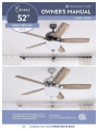
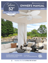
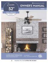
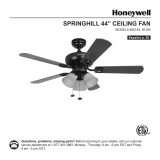
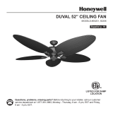
Prominence Home 51595 is a versatile ceiling fan with a range of features to enhance comfort and style in your home. It comes with a powerful motor that provides ample airflow, ensuring a cool and refreshing ambiance. The fan boasts a sleek design with five reversible blades in two finishes - one side is dark cherry and the other is walnut - allowing you to customize the look to match your décor. The fan's dimmable LED light kit adds warm and inviting illumination, creating a cozy atmosphere in your space.
Prominence Home 51595 is a versatile ceiling fan with a range of features to enhance comfort and style in your home. It comes with a powerful motor that provides ample airflow, ensuring a cool and refreshing ambiance. The fan boasts a sleek design with five reversible blades in two finishes - one side is dark cherry and the other is walnut - allowing you to customize the look to match your décor. The fan's dimmable LED light kit adds warm and inviting illumination, creating a cozy atmosphere in your space.


-
 1
1
-
 2
2
-
 3
3
-
 4
4
-
 5
5
-
 6
6
-
 7
7
-
 8
8
-
 9
9
-
 10
10
-
 11
11
-
 12
12
-
 13
13
-
 14
14


Prominence Home 51595 Owner's manual
- Category
- Household fans
- Type
- Owner's manual
Prominence Home 51595 is a versatile ceiling fan with a range of features to enhance comfort and style in your home. It comes with a powerful motor that provides ample airflow, ensuring a cool and refreshing ambiance. The fan boasts a sleek design with five reversible blades in two finishes - one side is dark cherry and the other is walnut - allowing you to customize the look to match your décor. The fan's dimmable LED light kit adds warm and inviting illumination, creating a cozy atmosphere in your space.
Ask a question and I''ll find the answer in the document
Finding information in a document is now easier with AI
Related papers
-
Prominence Home 51592 Owner's manual
-
Prominence Home 51431 Owner's manual
-
Prominence Home 50566 Owner's manual
-
Prominence Home Briarcrest 50749 Owner's manual
-
 Prominence Home 80018 Owner's manual
-
Prominence Home Enrora Owner's manual
-
Prominence Home 51586 Owner's manual
-
Prominence Home 51639 Owner's manual
-
Prominence Home 51865 Owner's manual
-
 Prominence Home 50650 Owner's manual


Other documents
-
 Honeywell Ceiling Fans 50202 User guide
-
 Honeywell Ceiling Fans 50184 User guide
-
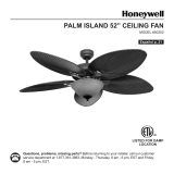
 Honeywell Ceiling Fans PALM ISLAND User manual
-
 Harbor Breeze 42073 Installation guide
-
 Honeywell Ceiling Fans 50199 User guide
-
 Honeywell Ceiling Fans 50207 User guide
-
 Honeywell Ceiling Fans 50190 User guide
-
Honeywell 51856 User manual
-
 Honeywell Ceiling Fans 50195 User manual
-
Honeywell Ceiling Fans 50197 User manual


