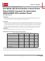
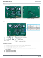
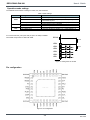
Rohm BD82A26MUF-M is a highly efficient LED driver designed for automotive applications. It features a 6-channel white LED driver with built-in current drivers, making it ideal for high brightness LED drive in automotive backlights. With a wide input voltage range of 3.0V to 48V, it can accommodate various power sources. The dimming function, controlled by PWM signal, allows for precise brightness adjustment. Additionally, it includes protection features such as overvoltage and overcurrent protection for safe operation.
Rohm BD82A26MUF-M is a highly efficient LED driver designed for automotive applications. It features a 6-channel white LED driver with built-in current drivers, making it ideal for high brightness LED drive in automotive backlights. With a wide input voltage range of 3.0V to 48V, it can accommodate various power sources. The dimming function, controlled by PWM signal, allows for precise brightness adjustment. Additionally, it includes protection features such as overvoltage and overcurrent protection for safe operation.


-
 1
1
-
 2
2
-
 3
3
-
 4
4
-
 5
5
-
 6
6
-
 7
7
-
 8
8
-
 9
9
-
 10
10
-
 11
11
-
 12
12


Rohm BD82A26MUF-M is a highly efficient LED driver designed for automotive applications. It features a 6-channel white LED driver with built-in current drivers, making it ideal for high brightness LED drive in automotive backlights. With a wide input voltage range of 3.0V to 48V, it can accommodate various power sources. The dimming function, controlled by PWM signal, allows for precise brightness adjustment. Additionally, it includes protection features such as overvoltage and overcurrent protection for safe operation.
Ask a question and I''ll find the answer in the document
Finding information in a document is now easier with AI
Related papers
-
Rohm BD82A26MUF-M User guide
-
Rohm BD7J200EFJ-EVK-002 User manual
-
-
-
-
-
-
-
-
Other documents
-
LG P705 User manual
-
Sierra Wireless AirPrime MC8092 Quick start guide
-
LG Electronics 20LS7D(C)-UB User manual
-
OMRON Automotive Electronics OUCG8D-246S-B User manual
-
ON Semiconductor LC87F1M16A User manual
-
Texas Instruments Single Dual 3Gbps HD SD SDI Cable Driver with Cable Detect Eval Bd User guide
-
MICROCHIP ADM00873 Operating instructions
-
Microchip Technology Microsemi PD70201EVB-25F-D-5 User manual
-
Sharp 28JW-74H User manual
-
ST Teseo-LIV3F User manual