XL R B ALAN CED
AUDI O OU TP UT
MIC 1
AN TEN NA-B AN TEN NA-A
DC 12V
/
600 mA
DC -PO WE R
362111109800
G3 SER IES
Gen eration 3
RISK OF ELECTRIC SHOC K
DO NOT OPEN
Taking apart or mo difying the
receive r may lead to elec tric shock,
fire, or dama ge to the recei ver and
will void yo ur warranty.
Mod el No.: V M-82U G3
(UHF Microp hone)
CALIFORNIA , UNITED STATES OF AMERICA
E-MAIL: sa les@better musicbuilder.c om
w ww .Be t te rM us icB ui ld er .c om
ENGINEERED AND DESIG N IN U.S.A.
SERIAL NO.
Bette r Music B uilde r
®
®
XL R B ALAN CED
AUDI O OU TP UT
MIC 2
MI XE D OU TP UT
MIC 1 & 2
¼” U NBAL ANCED
MIC 1 + MIC 2
ANTE NNA-A ANTE NNA-B
RISK OF ELECTRIC SHOC K
DO NOT OPEN
Taking apart or mo difying th e
receive r may lead to elec tric shock,
fire, or dama ge to the recei ver and
will void yo ur warranty.
AC-PO WER
120V / 60Hz
Mod el No.: V M-93C G2
(UHF Microp hone)
CALIFORNIA , UNITED STATES OF AMERICA
E-MAIL: s ales@bette rmusicbuilde r.com
w ww .B et te rM us ic Bui ld er .c om
ENGINEERED AND DES IGN IN U.S.A.
SERIAL NO.
Bette r Musi c Buil der
®
®
360110810500
G2 SERIES
Generati on 2
¼” UNBAL ANCEDXLR B ALANCE D
MICR OPHONE 2 AUD IO OUT
¼” UNBAL ANCEDXLR B ALANCE D
MICR OPHONE 1 AU DIO OUT
XLR
Balanced Input
XLR
Balanced Input
XLR
Balanced Input
XLR
Balanced Input
1/4"
Unbalanced Input
1/4"
Unbalanced Input
1/4"
Unbalanced Input
1/4"
Unbalanced Input
Set Up
BALANCED CONNECTION
5
AUDIO MIXER AMPLIFIER OR A KARAOKE UNIT INPUT TERMINAL
REAR VIEW
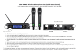
HARDWARE SETUP
HOW TO CONNECT AUDIO OUTPUT:
There are three rear outputs as shown in the below diagram:
1. MIC 2 BALANCED OUTPUT is balanced audio output using XLR connection.
The grounding of the balanced XLR connection delivers better quality signal and
reduces unwanted noise. This output enables adjusting MIC 2 effects
independently without affecting MIC 1 effects.
2. MIC 1 & MIC 2 MIXED UNBALANCED OUTPUT is unbalanced audio output
using ¼” connection. In effect, two channels are sharing one single signal. To
produce different effects on each microphone, MIC 1 and MIC 2 need their own
independent signals by using two separate XLR connections.
3. MIC 1 BALANCED OUTPUT is balanced audio output using XLR connection.
The grounding of the balanced XLR connection delivers better quality signal and
reduces unwanted noise. This output enables adjusting MIC 1 effects
independently without affecting MIC 2 effects.
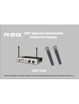
UHF WIRELESS SYSTEM DIAGRAM:
We highly recommend using balanced XLR connections if the distance between the
microphone receiver and the amplifier/mixer is more than 10 feet. The grounding of the
balanced XLR connection delivers better quality signal and reduces unwanted noise.
Recommend
1
MIC 2 BALANCED OUTPUT
(XLR BALANCED)
MIC 1 BALANCED
OUTPUT (XLR BALANCED)
3
MIXED OUTPUT
(¼” UNBALANCED)
2
UHF WIRELESS SYSTEM VM-82U G 3
MIC 1 HANDHELD MICROPHONE MIC 2 HANDHELD MICROPHONE
BAT
835.500