JL Audio SB-GM-SLVEXT/10W6v2 User manual
- Category
- Car speakers
- Type
- User manual
This manual is also suitable for

➔
➔
➔
➔
Stealthbox
®
INSTALLATION GUIDE
SB-GM-SXT/10W6v2, JL AUDIO, Inc 2006
Sheet SKU#011199 Revision 1/12/2006 Page 1
for the
SB-GM-SLVEXT/10W6v2
(1999-2005 Chevrolet Silverado /
GMC Sierra Extended Cab Trucks
with full rear bench seating.)
(These instructions show for both enclo-
sures. These enclosures are
sold separately )
This Stealthbox is a product which
requires professional installation skills and
tools.
Please read this installation guide thor-
oughly before beginning the project. It
will guide you step by step through the
installation.Several of the steps in this
process may require two people to
accomplish.
It is absolutely vital that the enclosure
be properly mounted to the vehicle
according to these instructions. Failure
to mount the enclosure properly pres-
ents two problems: 1) The sub-bass
performance will suffer due to the
movement of the enclosure caused by
the force exerted by the woofer(s) and
2) A loose enclosure presents a serious
safety hazard in the event of a collision
or sudden deceleration.
Please enjoy your JL Audio Stealthbox
responsibly.
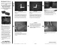
Passenger’s Side
STEP 1:
Remove all contents from the rear
floor area.
Remove the paper backing and place the sup-
plied wax square on the passenger’s side rear
floor.The middle of the wax square needs to
be placed 6.5”in front of the rear bulkhead
and 6.0”away from the transmission tunnel.
Driver’s Side
STEP 1:
Remove all contents from the rear
floor area.
Remove the paper backing and place the sup-
plied wax square on the driver’s side rear floor.
The middle of the wax square needs to be
placed 6.5”in front of the rear bulkhead and
6.0”away from the transmission tunnel.
STEP 3:
Thread in the supplied socket cup
set screw into the/each enclosure,leaving
about 1/2”of the treads exposed.
Make sure that the cup end of the set screw
is on the outside of the enclosure.
STEP 4:
Place the/each enclosure into posi-
tion and press down firmly.
Remove the/each enclosure.The wax square
should have an impression of the socket cup
set screw.
STEP 5: With the use of a 1/2” drill bit and drill.
Drill out the floor at the impression on the wax
square(s).
START
HERE
Continued on Next Page ➔
www.jlaudio.com
➔
➔
*CAUTION*
Before drilling, make sure that you are not going
to be drilling into any gas lines, brake lines, trans-
mission lines, electrical wiring, transfer case(4x4
vehicles) or anything else that might cause a
reduction in your weekly pay.Always wear eye
protection when drilling.
6.5”
6.5”
6.0”
6.0”
X
X

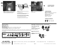
Specifications:
Enclosure Type: Ported
Driver Type: 10W6v2-D4
Nominal Impedance: 2Ω per woofer / can be rewired for 8Ω per woofer
Cont. Power Handling: 400Watts per woofer / 800Watts for system
JLAudio recommends using a high quality amplifier such as the JL Audio 500/1 or the JLAudio 1000/1. The diagram below shows
the recommended crossover, infrasonic filter and equalizer settings for either the 500/1 or the 1000/1 when being used to power
your Stealthbox®.
Included Hardware:
1) 3”x 3’ wax Square
1) 3/8”-16 x 2-1/4”Socket Cup Set Screw
1) 3/8”x 1-1/4” Fender Washer
1) 3/8” Flat Washer
1) 3/8”Split Lock Washer
1) 3/8”- 16 Hex Nut
10369 N. Commerce Pkwy, Miramar, Florida 33025-392 Phone: 954.443.1100 Fax: 954.443.1111
+12VDC RemoteGround
JL AUDIO 500/1
five-channel system amplifier
+
_
_
+
Subwoofer Output
MONO OUTPUT ONLY
40
45
55
65
85
120
200
Filter Freq. (Hz)
Mode / Slope
Off / 12dB / 24dB
Amp LP Filter
Infrasonic Freq. (Hz)
15
18
25
30
40
50
60
Off / 30Hz
Infrasonic Filter
0.5
0.7
1.1
1.6
2.7
4.3
"Q"
20
25
35
45
55
70
85
Center Freq.
0
+4
+10
+13
+15
Boost (dB)
Off / On
Bass EQ
Remote Bass Port
Advanced
Bass
Control
Preamp Output Section
Full Range / Amp Filter / Out Filter
Output Mode
Filter Slope
12dB / 24dB
40
45
55
65
85
120
200
Filter Freq. (Hz)
Left Ch. Right Ch.
Filter Mode
LP / HP
Amplifier Input Section
Input Sens.
Left Ch.
Right Ch.
Signal Sensing
Off / On
Input Voltage
Low / High
The JLAudio 500/1 or the JLAudio 1000/1 is a very versatile audio component. Please consult the owner’s manual for
detailed information about installing and tuning this amplifier.
➔➔➔
STEP 6: Run speaker wire to the/each enclosure
and attach to the speaker terminal cup. Check the
woofer(s) for proper operation at this time.
STEALTHBOX WALL
THREADED INSERT
VEHICLE SHEET METAL
FENDER WASHER
SOCKET CUP SET SCREW
LOCK WASHER
FLAT WASHER
HEX NUT
STEP 7: Back out the/each socket cup set screw
to expose about 1-1/2”.
Place the socket cup set screw through the mount-
ing hole that was drilled, inside the truck.
From the under side of the truck, place a supplied
fender washer, flat washer, lock washer and then hex
nut onto the/each socket cup set screw.
Secure tightly, using a 14mm socket and ratchet.
STEP 8: Lower the rear seat and replace all
removed contents.
➔
SB-GM-SXT/10W6v2, JL AUDIO, Inc 2006
Sheet SKU#011199 Revision 1/12/2006 Page 2
www.jlaudio.com
Mid/High Frequency Driver Information:
CONGRATULATIONS!
INSTALL COMPLETE.
ZR650-CSi
TR400-CXi
Front Location Driver Size:
6.5” Separates
Applicable JL Audio Products:
TR,VR,XR & ZR650-CSi
Rear Location Driver Size:
4”x 6”
Applicable JL Audio Products:
TR400-CXi
Cont.
From
Previous
Page
Difficulty Of Installation:
-
 1
1
-
 2
2


JL Audio SB-GM-SLVEXT/10W6v2 User manual
- Category
- Car speakers
- Type
- User manual
- This manual is also suitable for
Ask a question and I''ll find the answer in the document
Finding information in a document is now easier with AI
Related papers
-
JL Audio SB-N-ARMAD/10W6v2/DG User manual
-
-
-
-
-
-
JL Audio SB-GM-SLVCC/10W3v3/GA2 User manual
-
-
-