Mitsubishi Electronics MUZ-GB50VA User manual
- Category
- Split-system air conditioners
- Type
- User manual

SERVICE MANUAL
CONTENTS
1. TECHNICAL CHANGES ····································2
2. PART NAMES AND FUNCTIONS······················3
3. SPECIFICATION·················································3
4. NOISE CRITERIA CURVES·······························5
5. OUTLINES AND DIMENSIONS ·························6
6. WIRING DIAGRAM ············································7
7. REFRIGERANT SYSTEM DIAGRAM················8
8. PERFORMANCE CURVES································9
9. ACTUATOR CONTROL····································14
10. TROUBLESHOOTING······································15
11. DISASSEMBLY INSTRUCTIONS·····················34
12. RoHS PARTS LIST···········································38
Wireless type
Models
MUZ-GB50VA -
E1
SPLIT-TYPE, HEAT PUMP AIR CONDITIONERS
OUTDOOR UNIT
Indoor unit service manual
MSZ-GB·VA Series (OB454)
Refrigerant service manual
R410A REFRIGERANT (OBR01)
NOTE:
• This service manual describes technical data of the outdoor units.
HFC
utilized
R410A
Please void OB455.
Revision A:
• Compressor has been Changed.
No. OB455
REVISED EDITION-A
OB455A--1qxq 06.7.31 2:19 PM Page 1

2
1
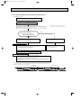
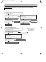
TECHNICAL CHANGES
MUZ-GA50VA - ➔ MUZ- GB50VA -
E1E1
1. Refrigerant filling capacity has been changed.
2. Outdoor electronic control P.C. board has been changed.
Revision A:
• Compressor has been changed.
Previous
New
Model
SNB130FLDH
SNB130FLDH1
RoHS PARTS LIST number
E12 851 900
E12 939 900
OB455A--1qxq 06.7.31 2:19 PM Page 2

3
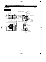
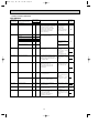
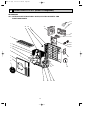
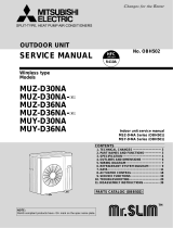
PART NAMES AND FUNCTIONS
2
3
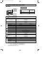
SPECIFICATION
Air inlet
Piping
Air outlet
(back and side)
Drain hose
Drain outlet
MUZ-GB50VA
Outdoor model
Function
Power supply
Capacity Rated frequency(Min.-Max.)
Dehumidification
Air flow ✽1
(High/Low)
Power outlet
Running current ✽1
Power input ✽1
Power factor ✽1
Starting current ✽1
Compressor motor current ✽1
Fan motor current ✽1
Model
Output
Winding
resistance(at 20:)
Model
Winding
resistance(at 20:)
Dimensions WOHOD
Weight
Sound level ✽1
(High/Low)
Fan speed (High/Low)
Fan speed regulator
Refrigerant filling
capacity(R410A)
Refrigeration oil (Model)
kW
r/h
K /h
A
A
W
%
A
A
A
✽1
W
"
"
mm
kg
dB(A)
rpm
kg
Compressor
Fan
motor
Special
remarks
Capacity
Electrical
data
Coefficient of performance(C.O.P)
Single phase
230V,50Hz
20
97
7.46
0.32
SNB130FLDH or SNB130FLDH1
850
U-V 0.45 W-U 0.45
V-W 0.45
RC0J60-AA
BLK-WHT 15.2
WHT-RED 15.2
RED-BLK 15.2
840o850o330
53
2
1.50
NEO22
Cooling
5.0(0.9-5.8)
2.5
2,940/1,650
7.23
1,610
6.91
3.03
52/51
800/480
Heating
5.8(0.9-7.8)
—
2,940/2,210
7.43
1,660
7.11
3.41
55/53
800/620
MUZ-GB50VA
NOTE : Test conditions are based on ISO 5151.
Cooling : Indoor Dry-bulb temperature 27:Wet-bulb temperature 19:
Outdoor Dry-bulb temperature 35:Wet-bulb temperature 24:
Heating : Indoor Dry-bulb temperature 20:Wet-bulb temperature 15:
Outdoor Dry-bulb temperature 7: Wet-bulb temperature 6:
Refrigerant piping length (one way): 5m
✽1 Measured under rated operating frequency
ACCESSORIES
1
2
Drain socket
Drain cap [33
1
2
MUZ-GB50VA
OB455A--1qxq 06.7.31 2:19 PM Page 3

4
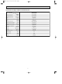
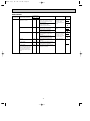
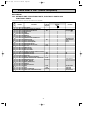
Specifications and rating conditions of main electric parts
Model
Item
Current transformer
Current transformer
Smoothing capacitor
Fuse
Fuse
Fuse
Expansion valve coil
Intelligent power module
Intelligent power module
Reactor
Power factor controller
Resistor
Resistor
Resistor
Solenoid coil relay
Terminal block
Terminal block
Relay
R.V. coil
MUZ-GB50VA
(CT1,2)
(CT61)
(CB1,2,3)
(F64)
(F801)
(F911)
(LEV)
(IPM)
(HC930)
(L)
(PFC)
(R64A,B)
(R937A,B)
(RS1~4)
(SSR61)
(TB1)
(TB2)
(X64)
(21S4)
ETQ19Z68AY
ETQ19Z53AY
560+ 450V
250V 2A
250V 3.15A
250V 1A
CAM-MD12ME
PS21244-A
PS21661-RZ
340µH 20A
PS51259-A
10
"
10W
1.1
"
2W 2%
0.04
"
7W
TLP3506
3P
3P
G4A
LD30013
OB455A--1qxq 06.7.31 2:19 PM Page 4

5
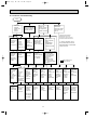
4
NOISE CRITERIA CURVES
OUTDOOR UNIT
MICROPHONE
1m
COOLING
FUNCTION
SPL(dB(A)) LINE
High
FAN SPEED
HEATING
52
55
90
80
70
60
50
40
30
20
10
63 125 250 500 1000 2000 4000 8000
NC-60
NC-50
NC-40
NC-30
NC-20
NC-70
BAND CENTER FREQUENCIES, Hz
Test conditions,
Cooling : Dry-bulb temperature 35: Wet-bulb temperature 24:
APPROXIMATE
THRESHOLD OF
HEARING FOR
CONTINUOUS
NOISE
Heating : Dry-bulb temperature 7: Wet-bulb temperature 6:
OCTAVE BAND SOUND PRESSURE LEVEL, 0dB=20µPa
MUZ-GB50VA
OB455A--1qxq 06.7.31 2:19 PM Page 5

6
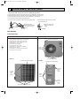
OUTLINES AND DIMENSIONS
5
Unit: mm
OUTDOOR UNIT
MUZ-GB50VA
30-
35-
155
90
198
40
515
299
66
34
51
330
360
850
430
500
80
121
840
Open as a rule
500mm or more if
the front and both
sides are open
100mm or more
200mm or more if
there are obstacles
to both sides
Open as a rule
500mm or more if the back,
both sides and top are open
350mm or more
100mm or more
Service panel
Gas refrigerant
pipe joint
Refrigerant pipe
(flared) [12.7
Liquid refrigerant
pipe joint
Refrigerant pipe
(flared) [6.35
REQUIRED SPACE
OB455A--1qxq 06.7.31 2:19 PM Page 6

7
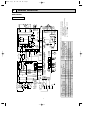
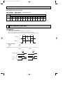
WIRING DIAGRAM
6
MUZ-GB50VA
R64B
YLW
230V~
12-24V
CN912
CN663
WHT
BLU
NOISE
FILTER
P.C.BOARD
BRN
TO INDOOR
UNIT
CONNECTING
RED
S3
RT65
21
CN61
13
GRN/YLW
5
PFC
GRN
LD9
POWER
BOARD
RT64
21
CN3
RED
WHT
RS2
RS1
R64A
RS3
RS4
F801
CN901
NR64
ELECTRONIC
CONTROL
P.C.BOARD
CB1
CB2
CB3
HC930
IPM
NF
BLK
BLK
BLK
BLK
WHT
RED
YLW
BLU
ORN
PNK
GRY
BLU
WHT
GRN
GRN
BLU
BLU
BLK
BLK
BLK
BLK
BLK
BLK
BLK
BLK
BLK
BLK
BLK
RED
BLU
L
CT2
CT1
SSR61
U
6
CN7954123 78
CN661
W
CN4
TB2
S1
1
CN601
3
S2
1567
CN702
5321
CN781
13
CN701
12
12
CN931
LD1LD2
T801
R937A
R937B
CN801
23134512
MF
CN932
3X64
5123
LDE2
12
CT61
TAB1
F64
F911
LDE1
21S4
POWER SUPPLY
~/N 230V 50Hz
TAB2
N
PE
L
TB1
CIRCUIT
BREAKER
4
1
RED
YLW
3
2
RED
S
R
21
CN903
21
CN902
21
CN5
6543 1
CN2
27
TAB4
V
MC
W
U
V
WHT
RT61 RT62 RT68
LEV
OUTDOOR UNIT
:Terminal block :Connector
3.Symbols below indicate.
2.Use copper conductors only (for field wiring).
diagram for servicing.
refer to the indoor unit electric wiring
1.About the indoor side electric wiringNOTES:
SYMBOL
NAME
SYMBOL
NAME
CURRENT TRANSFORMER
FUSE (T1AL 250V)
LEV
EXPANSION VALVE COIL
L
REACTOR
IPM
INTELLIGENT POWER MODULE
CT61
FUSE (T2AL 250V)
F64
CT1, 2
CURRENT TRANSFORMER
HC930
INTELLIGENT POWER MODULE
F911
F801
FUSE (T3.15AL 250V)
SMOOTHING CAPACITOR
CB1~3
OUTDOOR FAN MOTOR
POWER FACTOR CONTROLLER
NOISE FILTER
RT61
DISCHARGE TEMPERATURE THERMISTOR
RS1~4
RESISTOR
R937A, B
RESISTOR
MF
MC
COMPRESSOR
R64A,B
RESISTOR
PFC
NF
NR64
VARISTOR
AMBIENT TEMPERATURE THERMISTOR
SOLENOID COIL RELAY
21S4
R.V. COIL
X64
RELAY
TB1
TERMINAL BLOCK
TB2
TERMINAL BLOCK
RT65
FIN TEMPERATURE THERMISTOR
RT64
T801
TRANSFORMER
SSR61
RT68
OUTDOOR HEAT EXCHANGER
TEMPERATURE THERMISTOR
DEFROST THERMISTOR
RT62
NAME
SYMBOL
OB455A--1qxq 06.7.31 2:19 PM Page 7

8
7
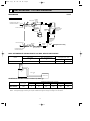
REFRIGERANT SYSTEM DIAGRAM
MUZ-GB50VA
OUTDOOR UNIT
Unit:mm
Outdoor
heat
exchanger
Flared connection
Defrost
thermistor
RT61
Discharge
temperature
thermistor
RT62
Flared connection
Stop valve
Stop valve
(with service port)
Capillary tube
[3.6✕[2.4✕50
Refrigerant flow in cooling
Compressor
4-way valve
Refrigerant flow in heating
Refrigerant pipe [12.7
(with heat insulator)
Refrigerant pipe [6.35
(with heat insulator)
LEV
R.V. coil
OFF
ON
Muffler
#100
Strainer
#100
Receiver
Outdoor heat
exchanger
temperature
thermistor
RT68
Ambient
temperature
thermistor
RT65
Strainer
#100
ADDITIONAL REFRIGERANT CHARGE (R410A:g)
Max. length
A
Max. Height
difference
B
Indoor
unit
Outdoor unit
MAX. REFRIGERANT PIPING LENGTH and MAX. HEIGHT DIFFERENCE
Max. length
A
30
Max. Height difference
B
15
Model
Gas
12.7
Liquid
6.35
Piping size O.D : mm
Refrigerant piping : m
MUZ-GB50VA
Model
MUZ-GB50VA
Refrigerant piping length (one way)
Outdoor unit
precharged
1,500
15m
160
20m
260
25m
360
30m
460
7m
0
10m
60
Calculation : Xg=20g/m ✕ (Refrigerant piping length (m)–7)
NOTE : Refrigerant piping exceeding 7m requires additional refrigerant charge according to the calculation.
OB455A--1qxq 06.7.31 2:19 PM Page 8

9
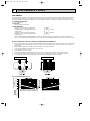
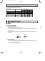
PERFORMANCE CURVES8
The standard data contained in these specifications apply only to the operation of the air conditioner under normal conditions.
Since operating conditions vary according to the areas where these units are installed. The following information has been
provided to clarify the operating characteristics of the air conditioner under the conditions indicated by the performance curve.
(1) GUARANTEED VOLTAGE
207 ~ 253V, 50Hz
(2) AIR FLOW
Air flow should be set at MAX.
(3) MAIN READINGS
(1) Indoor intake air wet-bulb temperature : °C [WB]
(2) Indoor outlet air wet-bulb temperature : °C [WB]
(3) Outdoor intake air dry-bulb temperature : °C [DB]
(4) Total input: W
(5) Indoor intake air dry-bulb temperature : °C [DB]
(6) Outdoor intake air wet-bulb temperature : °C [WB]
(7) Total input : W
Indoor air wet/dry-bulb temperature difference on the left side of the following chart shows the difference between the
indoor intake air wet/dry-bulb temperature and the indoor outlet air wet/dry-bulb temperature for your reference at service.
}
}
Cooling
Heating
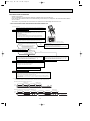
How to measure the indoor air wet-bulb / dry-bulb temperature difference
1. Attach at least 2 sets of wet and dry-bulb thermometers to the indoor air intake as shown in the figure, and at least 2 sets
of wet and dry-bulb thermometers to the indoor air outlet. The thermometers must be attached to the position where air
speed is high.
2. Attach at least 2 sets of wet and dry-bulb thermometers to the outdoor air intake.
Cover the thermometers to prevent direct rays of the sun.
3. Check that the air filter is cleaned.
4. Open windows and doors of room.
5. Press the EMERGENCY OPERATION switch once (twice) to start the EMERGENCY COOL (HEAT) MODE.
6. When system stabilizes after more than 15 minutes, measure temperature and take an average temperature.
7. 10 minutes later, measure temperature again and check that the temperature does not change.
MUZ-GB50VA
INDOOR UNIT
OUTDOOR UNIT
Wet and dry-bulb
thermometers
Wet and dry-bulb
thermometers
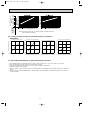
Indoor air Wet-bulb temperature
difference (:)
MSZ-GB50VA
8.7
8.0
7.3
6.6
5.9
5.3
Rated frequency 79Hz
Outdoor intake air Dry-bulb temperature (:)
Outdoor intake air Dry-bulb temperature (:)
In
d
o
o
r in
ta
k
e
a
ir W
e
t-b
u
lb
te
m
p
e
ra
tu
re
(
:
)
Indoor intake air W
et-bulb tem
perature (
:
)
MUZ-GB50VA
8-1. Capacity and input curves
OB455A--1qxq 06.7.31 2:19 PM Page 9

10
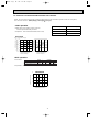
Indoor air Dry-bulb temperature
difference (
:)
In
d
o
o
r in
ta
k
e
a
ir
D
r
y
-b
u
lb
te
m
p
e
r
a
tu
r
e
(
:
)
Outdoor intake air Wet-bulb temperature (:)
Outdoor intake air Wet-bulb temperature (:)
In
d
o
o
r
in
ta
k
e
a
ir D
r
y
-b
u
lb
te
m
p
e
ra
tu
r
e
(
:
)
24.1
22.3
20.4
18.5
16.7
14.8
13.0
11.1
Rated frequency 82Hz
MUZ-GB50VA
MSZ-GB50VA
NOTE:The above broken lines are for the heating operation without any
frost and defrost operation.
8-2. Capacity and input correction by operational frequency of compressor
Capacity correction factors
Input correction factors
Input correction factors
Capacity correction factors
Correction of Cooling capacity
The operational frequency of compressor
Correction of Cooling total input
The operational frequency of compressor
Correction of Heating total input
The operational frequency of compressor
Correction of Heating capacity
The operational frequency of compressor
MUZ-GB50VA
(Hz)
0 50 100 150
0.0
0.5
1.0
1.5
(Hz)
(Hz)
(Hz)
0 50 100 150
0.0
0.5
1.0
1.5
0 50 100 150
0.0
0.5
1.0
1.5
0 50 100 150
0.0
0.5
1.0
1.5
0 50 100 150
0.0
0.5
1.0
1.5
2.0
1. Press EMERGENCY OPERATION switch to COOL or HEAT mode (COOL : Press once, HEAT : Press twice).
2. Test run operation starts and continues to operate for 30 minutes.
3. Compressor operates at rated frequency in COOL mode or 58Hz in HEAT mode.
4. Indoor fan operates at High speed.
5. After 30 minutes, test run operation finishes and EMERGENCY OPERATION starts (Operation frequency of compressor
varies).
6. To cancel test run operation (EMERGENCY OPERATION), press EMERGENCY OPERATION switch or any button on
remote controller.
8-3. TEST RUN OPERATION (How to operate fixed-frequency operation)
OB455A--1qxq 06.7.31 2:19 PM Page 10

11
COOL operation
1 Both indoor and outdoor unit are under the
same temperature/humidity condition.
2 Operation : TEST RUN OPERATION (refer to 8-3.)
Dry-bulb temperature(:)
Relative humidity(%)
20
50
25
60
30 70
8-4. OUTDOOR LOW PRESSURE AND OUTDOOR UNIT CURRENT
Ambient temperature(˚C)
Ambient humidity(%)
18 32
15 20
50
25
60
30
70 (%)
35(˚C)
Ambient temperature(˚C)
Ambient humidity(%)
18 32
15 20
50
25
60
30
70 (%)
35(˚C)
79Hz
MUZ-GB50VA
(MPa [Gauge])
(kgf/F [Gauge])
79Hz
Outdoor low pressure
Outdoor unit current(A)
4
5
6
7
8
0.5
0.6
0.7
0.8
0.9
1.0
5
6
7
8
9
10
1 Condition :
2 Operation : TEST RUN OPERATION (refer to 8-3.)
HEAT operation
Dry bulb temperature (°C)
Indoor
20.0
14.5
2
1
Outdoor
7
6
15
12
20.0
14.5
Wet bulb temperature (°C)
0 5 10 15 20 25(˚C)
4
5
6
7
8
Outdoor unit current (A)
Ambient temperature(˚C)
MUZ-GB50VA
2
58 Hz
NOTE: The unit of pressure has been changed to MPa based on the international system of units (SI unit system).
The conversion factor is: 1(MPa [Gauge] = 10.2 (Kgf/
ff
[Gauge])
OB455A--1qxq 06.7.31 2:19 PM Page 11

12
MSZ-GB50VA : MUZ-GB50VA
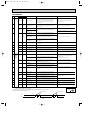
21 18 5.88 3.00 0.51 1320 5.63 2.87 0.51 1386 5.40 2.75 0.51 1452 5.20 2.65 0.51 1518
21 20 6.13 2.39 0.39 1386 5.88 2.29 0.39 1469 5.70 2.22 0.39 1502 5.50 2.15 0.39 1568
22 18 5.88 3.23 0.55 1320 5.63 3.09 0.55 1386 5.40 2.97 0.55 1452 5.20 2.86 0.55 1518
22 20 6.13 2.63 0.43 1386 5.88 2.53 0.43 1469 5.70 2.45 0.43 1502 5.50 2.37 0.43 1568
22 22 6.38 1.98 0.31 1436 6.15 1.91 0.31 1526 6.00 1.86 0.31 1568 5.75 1.78 0.31 1634
23 18 5.88 3.47 0.59 1320 5.63 3.32 0.59 1386 5.40 3.19 0.59 1452 5.20 3.07 0.59 1518
23 20 6.13 2.88 0.47 1386 5.88 2.76 0.47 1469 5.70 2.68 0.47 1502 5.50 2.59 0.47 1568
23 22 6.38 2.23 0.35 1436 6.15 2.15 0.35 1526 6.00 2.10 0.35 1568 5.75 2.01 0.35 1634
24 18 5.88 3.70 0.63 1320 5.63 3.54 0.63 1386 5.40 3.40 0.63 1452 5.20 3.28 0.63 1518
24 20 6.13 3.12 0.51 1386 5.88 3.00 0.51 1469 5.70 2.91 0.51 1502 5.50 2.81 0.51 1568
24 22 6.38 2.49 0.39 1436 6.15 2.40 0.39 1526 6.00 2.34 0.39 1568 5.75 2.24 0.39 1634
24 24 6.70 1.81 0.27 1502 6.45 1.74 0.27 1584 6.30 1.70 0.27 1634 6.10 1.65 0.27 1716
25 18 5.88 3.94 0.67 1320 5.63 3.77 0.67 1386 5.40 3.62 0.67 1452 5.20 3.48 0.67 1518
25 20 6.13 3.37 0.55 1386 5.88 3.23 0.55 1469 5.70 3.14 0.55 1502 5.50 3.03 0.55 1568
25 22 6.38 2.74 0.43 1436 6.15 2.64 0.43 1526 6.00 2.58 0.43 1568 5.75 2.47 0.43 1634
25 24 6.70 2.08 0.31 1502 6.45 2.00 0.31 1584 6.30 1.95 0.31 1634 6.10 1.89 0.31 1716
26 18 5.88 4.17 0.71 1320 5.63 3.99 0.71 1386 5.40 3.83 0.71 1452 5.20 3.69 0.71 1518
26 20 6.13 3.61 0.59 1386 5.88 3.47 0.59 1469 5.70 3.36 0.59 1502 5.50 3.25 0.59 1568
26 22 6.38 3.00 0.47 1436 6.15 2.89 0.47 1526 6.00 2.82 0.47 1568 5.75 2.70 0.47 1634
26 24 6.70 2.35 0.35 1502 6.45 2.26 0.35 1584 6.30 2.21 0.35 1634 6.10 2.14 0.35 1716
26 26 6.90 1.59 0.23 1584 6.70 1.54 0.23 1667 6.60 1.52 0.23 1716 6.40 1.47 0.23 1766
27 18 5.88 4.41 0.75 1320 5.63 4.22 0.75 1386 5.40 4.05 0.75 1452 5.20 3.90 0.75 1518
27 20 6.13 3.86 0.63 1386 5.88 3.70 0.63 1469 5.70 3.59 0.63 1502 5.50 3.47 0.63 1568
27 22 6.38 3.25 0.51 1436 6.15 3.14 0.51 1526 6.00 3.06 0.51 1568 5.75 2.93 0.51 1634
27 24 6.70 2.61 0.39 1502 6.45 2.52 0.39 1584 6.30 2.46 0.39 1634 6.10 2.38 0.39 1716
27 26 6.90 1.86 0.27 1584 6.70 1.81 0.27 1667 6.60 1.78 0.27 1716 6.40 1.73 0.27 1766
28 18 5.88 4.64 0.79 1320 5.63 4.44 0.79 1386 5.40 4.27 0.79 1452 5.20 4.11 0.79 1518
28 20 6.13 4.10 0.67 1386 5.88 3.94 0.67 1469 5.70 3.82 0.67 1502 5.50 3.69 0.67 1568
28 22 6.38 3.51 0.55 1436 6.15 3.38 0.55 1526 6.00 3.30 0.55 1568 5.75 3.16 0.55 1634
28 24 6.70 2.88 0.43 1502 6.45 2.77 0.43 1584 6.30 2.71 0.43 1634 6.10 2.62 0.43 1716
28 26 6.90 2.14 0.31 1584 6.70 2.08 0.31 1667 6.60 2.05 0.31 1716 6.40 1.98 0.31 1766
29 18 5.88 4.88 0.83 1320 5.63 4.67 0.83 1386 5.40 4.48 0.83 1452 5.20 4.32 0.83 1518
29 20 6.13 4.35 0.71 1386 5.88 4.17 0.71 1469 5.70 4.05 0.71 1502 5.50 3.91 0.71 1568
29 22 6.38 3.76 0.59 1436 6.15 3.63 0.59 1526 6.00 3.54 0.59 1568 5.75 3.39 0.59 1634
29 24 6.70 3.15 0.47 1502 6.45 3.03 0.47 1584 6.30 2.96 0.47 1634 6.10 2.87 0.47 1716
29 26 6.90 2.42 0.35 1584 6.70 2.35 0.35 1667 6.60 2.31 0.35 1716 6.40 2.24 0.35 1766
30 18 5.88 5.11 0.87 1320 5.63 4.89 0.87 1386 5.40 4.70 0.87 1452 5.20 4.52 0.87 1518
30 20 6.13 4.59 0.75 1386 5.88 4.41 0.75 1469 5.70 4.28 0.75 1502 5.50 4.13 0.75 1568
30 22 6.38 4.02 0.63 1436 6.15 3.87 0.63 1526 6.00 3.78 0.63 1568 5.75 3.62 0.63 1634
30 24 6.70 3.42 0.51 1502 6.45 3.29 0.51 1584 6.30 3.21 0.51 1634 6.10 3.11 0.51 1716
30 26 6.90 2.69 0.39 1584 6.70 2.61 0.39 1667 6.60 2.57 0.39 1716 6.40 2.50 0.39 1766
31 18 5.88 5.35 0.91 1320 5.63 5.12 0.91 1386 5.40 4.91 0.91 1452 5.20 4.73 0.91 1518
31 20 6.13 4.84 0.79 1386 5.88 4.64 0.79 1469 5.70 4.50 0.79 1502 5.50 4.35 0.79 1568
31 22 6.38 4.27 0.67 1436 6.15 4.12 0.67 1526 6.00 4.02 0.67 1568 5.75 3.85 0.67 1634
31 24 6.70 3.69 0.55 1502 6.45 3.55 0.55 1584 6.30 3.47 0.55 1634 6.10 3.36 0.55 1716
31 26 6.90 2.97 0.43 1584 6.70 2.88 0.43 1667 6.60 2.84 0.43 1716 6.40 2.75 0.43 1766
32 18 5.88 5.58 0.95 1320 5.63 5.34 0.95 1386 5.40 5.13 0.95 1452 5.20 4.94 0.95 1518
32 20 6.13 5.08 0.83 1386 5.88 4.88 0.83 1469 5.70 4.73 0.83 1502 5.50 4.57 0.83 1568
32 22 6.38 4.53 0.71 1436 6.15 4.37 0.71 1526 6.00 4.26 0.71 1568 5.75 4.08 0.71 1634
32 24 6.70 3.95 0.59 1502 6.45 3.81 0.59 1584 6.30 3.72 0.59 1634 6.10 3.60 0.59 1716
32 26 6.90 3.24 0.47 1584 6.70 3.15 0.47 1667 6.60 3.10 0.47 1716 6.40 3.01 0.47 1766
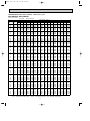
INDOOR INDOOR
CAPACITY:5.0(kW)
INPUT:1650(W)SHF:0.69
21
OUTDOOR DB(
:
)
25 27 30
WB(:)
Q SHC SHF Q SHC SHF Q SHC SHF Q SHC SHFINPUT INPUT INPUT INPUT
DB(:)
PERFORMANCE DATA COOL operation Rated frequency 79Hz
NOTE Q : Total capacity (kW) SHF : Sensible heat factor DB : Dry-bulb temperature
SHC : Sensible heat capacity (kW) INPUT : Total power input (W) WB : Wet-bulb temperature
OB455A--1qxq 06.7.31 2:19 PM Page 12

13
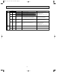
21 18 4.90 2.50 0.51 1617 4.50 2.30 0.51 1716 4.30 2.19 0.51 1749
21 20 5.15 2.01 0.39 1683 4.80 1.87 0.39 1766 4.60 1.79 0.39 1815
22 18 4.90 2.70 0.55 1617 4.50 2.48 0.55 1716 4.30 2.37 0.55 1749
22 20 5.15 2.21 0.43 1683 4.80 2.06 0.43 1766 4.60 1.98 0.43 1815
22 22 5.45 1.69 0.31 1749 5.10 1.58 0.31 1848 4.90 1.52 0.31 1881
23 18 4.90 2.89 0.59 1617 4.50 2.66 0.59 1716 4.30 2.54 0.59 1749
23 20 5.15 2.42 0.47 1683 4.80 2.26 0.47 1766 4.60 2.16 0.47 1815
23 22 5.45 1.91 0.35 1749 5.10 1.79 0.35 1848 4.90 1.72 0.35 1881
24 18 4.90 3.09 0.63 1617 4.50 2.84 0.63 1716 4.30 2.71 0.63 1749
24 20 5.15 2.63 0.51 1683 4.80 2.45 0.51 1766 4.60 2.35 0.51 1815
24 22 5.45 2.13 0.39 1749 5.10 1.99 0.39 1848 4.90 1.91 0.39 1881
24 24 5.75 1.55 0.27 1815 5.40 1.46 0.27 1898 5.25 1.42 0.27 1947
25 18 4.90 3.28 0.67 1617 4.50 3.02 0.67 1716 4.30 2.88 0.67 1749
25 20 5.15 2.83 0.55 1683 4.80 2.64 0.55 1766 4.60 2.53 0.55 1815
25 22 5.45 2.34 0.43 1749 5.10 2.19 0.43 1848 4.90 2.11 0.43 1881
25 24 5.75 1.78 0.31 1815 5.40 1.67 0.31 1898 5.25 1.31 0.25 1947
26 18 4.90 3.48 0.71 1617 4.50 3.20 0.71 1716 4.30 3.05 0.71 1749
26 20 5.15 3.04 0.59 1683 4.80 2.83 0.59 1766 4.60 2.71 0.59 1815
26 22 5.45 2.56 0.47 1749 5.10 2.40 0.47 1848 4.90 2.30 0.47 1881
26 24 5.75 2.01 0.35 1815 5.40 1.89 0.35 1898 5.25 1.21 0.23 1947
26 26 6.05 1.39 0.23 1881 5.70 1.31 0.23 1964 5.50 1.27 0.23 2013
27 18 4.90 3.68 0.75 1617 4.50 3.38 0.75 1716 4.30 3.23 0.75 1749
27 20 5.15 3.24 0.63 1683 4.80 3.02 0.63 1766 4.60 2.90 0.63 1815
27 22 5.45 2.78 0.51 1749 5.10 2.60 0.51 1848 4.90 2.50 0.51 1881
27 24 5.75 2.24 0.39 1815 5.40 2.11 0.39 1898 5.25 1.10 0.21 1947
27 26 6.05 1.63 0.27 1881 5.70 1.54 0.27 1964 5.50 1.49 0.27 2013
28 18 4.90 3.87 0.79 1617 4.50 3.56 0.79 1716 4.30 3.40 0.79 1749
28 20 5.15 3.45 0.67 1683 4.80 3.22 0.67 1766 4.60 3.08 0.67 1815
28 22 5.45 3.00 0.55 1749 5.10 2.81 0.55 1848 4.90 2.70 0.55 1881
28 24 5.75 2.47 0.43 1815 5.40 2.32 0.43 1898 5.25 1.00 0.19 1947
28 26 6.05 1.88 0.31 1881 5.70 1.77 0.31 1964 5.50 1.71 0.31 2013
29 18 4.90 4.07 0.83 1617 4.50 3.74 0.83 1716 4.30 3.57 0.83 1749
29 20 5.15 3.66 0.71 1683 4.80 3.41 0.71 1766 4.60 3.27 0.71 1815
29 22 5.45 3.22 0.59 1749 5.10 3.01 0.59 1848 4.90 2.89 0.59 1881
29 24 5.75 2.70 0.47 1815 5.40 2.54 0.47 1898 5.25 0.89 0.17 1947
29 26 6.05 2.12 0.35 1881 5.70 2.00 0.35 1964 5.50 1.93 0.35 2013
30 18 4.90 4.26 0.87 1617 4.50 3.92 0.87 1716 4.30 3.74 0.87 1749
30 20 5.15 3.86 0.75 1683 4.80 3.60 0.75 1766 4.60 3.45 0.75 1815
30 22 5.45 3.43 0.63 1749 5.10 3.21 0.63 1848 4.90 3.09 0.63 1881
30 24 5.75 2.93 0.51 1815 5.40 2.75 0.51 1898 5.25 0.79 0.15 1947
30 26 6.05 2.36 0.39 1881 5.70 2.22 0.39 1964 5.50 2.15 0.39 2013
31 18 4.90 4.46 0.91 1617 4.50 4.10 0.91 1716 4.30 3.91 0.91 1749
31 20 5.15 4.07 0.79 1683 4.80 3.79 0.79 1766 4.60 3.63 0.79 1815
31 22 5.45 3.65 0.67 1749 5.10 3.42 0.67 1848 4.90 3.28 0.67 1881
31 24 5.75 3.16 0.55 1815 5.40 2.97 0.55 1898 5.25 0.68 0.13 1947
31 26 6.05 2.60 0.43 1881 5.70 2.45 0.43 1964 5.50 2.37 0.43 2013
32 18 4.90 4.66 0.95 1617 4.50 4.28 0.95 1716 4.30 4.09 0.95 1749
32 20 5.15 4.27 0.83 1683 4.80 3.98 0.83 1766 4.60 3.82 0.83 1815
32 22 5.45 3.87 0.71 1749 5.10 3.62 0.71 1848 4.90 3.48 0.71 1881
32 24 5.75 3.39 0.59 1815 5.40 3.19 0.59 1898 5.25 0.58 0.11 1947
32 26 6.05 2.84 0.47 1881 5.70 2.68 0.47 1964 5.50 2.59 0.47 2013
INDOOR INDOOR
35
OUTDOOR DB(
:
)
40 43
WB(:)
Q SHC SHF Q SHC SHF Q SHC SHFINPUT INPUT INPUT
DB(:)
CAPACITY:5.0(kW)
INPUT:1650(W)SHF:0.69
PERFORMANCE DATA COOL operation Rated frequency 79Hz
NOTE Q : Total capacity (kW) SHF : Sensible heat factor DB : Dry-bulb temperature
SHC : Sensible heat capacity (kW) INPUT : Total power input (W) WB : Wet-bulb temperature
MSZ-GB50VA : MUZ-GB50VA
OB455A--1qxq 06.7.31 2:19 PM Page 13

14
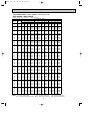
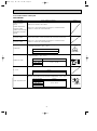
PERFORMANCE DATA HEAT operation
CAPACITY:5.8(kW)
INPUT:1700(W)
OUTDOOR WB(
:
)
INDOOR
-10 -5 0 5 10 15 20
DB(
:
)
Q INPUT Q INPUT Q INPUT Q INPUT Q INPUT Q INPUT Q INPUT
15
21
26
3.65 1105 4.41 1326 5.16 1496 5.92 1615 6.67 1717 7.37 1768 8.12 1802
3.48 1190 4.18 1411 4.93 1564 5.63 1683 6.38 1768 7.08 1819 7.80 1887
3.13 1275 3.89 1496 4.58 1649 5.34 1768 6.09 1853 6.79 1904 7.54 1955
MSZ-GB50VA : MUZ-GB50VA Rated frequency 75Hz
ACTUATOR CONTROL
9
MUZ-GB50VA
9-2. R.V. coil control
Heating
. . . . . . . . . . . . . . . .
ON
Cooling. . . . . . . . . . . . . . . . . OFF
Dry
. . . . . . . . . . . . . . . . . . . .
OFF
NOTE: The 4-way valve reverses for 5 seconds right before start-up of the compressor.
ON
OFF
ON
OFF
Outdoor fan
motor
Compressor
5 seconds 15 seconds
ON
OFF
Compressor
Outdoor fan
motor
ON
OFF
<COOL>
5 seconds
<HEAT>
5 seconds
R.V.coil
ON
OFF
ON or OFF
ON or OFF
9-1. Outdoor fan motor control
The fan motor turns ON/OFF, interlocking with the compressor.
[ON] The fan motor turns ON 5 seconds before the compressor starts up.
[OFF] The fan motor turns OFF 15 seconds after the compressor has stopped running.
NOTE Q : Total capacity (kW) INPUT : Total power input (W) DB : Dry-bulb temperature WB : Wet-bulb temperature
OB455A--1qxq 06.7.31 2:19 PM Page 14

15
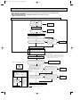
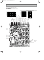
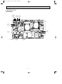
10
TROUBLESHOOTING
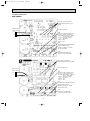
3. Troubleshooting procedure
1) First, check if the OPERATION INDICATOR lamp on the indoor unit is flashing on and off to indicate an abnormality.
To make sure, check how many times the abnormality indication is flashing on and off before starting service work.
2) Before servicing check that the connector and terminal are connected properly.
3) If the electronic control P.C. board is supposed to be defective, check the copper foil pattern for disconnection and
the components for bursting and discoloration.
4) When troubleshooting, refer to 10-2., 10-3. and 10-4.
10-1. Cautions on troubleshooting
1. Before troubleshooting, check the following:
1) Check the power supply voltage.
2) Check the indoor/outdoor connecting wire for mis-wiring.
2. Take care the following during servicing.
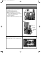
1) Before servicing the air conditioner, be sure to turn OFF the main unit first with the remote controller, and then after
confirming the horizontal vane is closed, turn off the breaker and / or disconnect the power plug.
2) Be sure to turn OFF the power supply before removing the front panel, the cabinet, the top panel, and the electronic
control P.C. board.
3) When removing the electrical parts, be careful to the residual voltage of smoothing capacitor.
4) When removing the electronic control P.C. board, hold the edge of the board with care NOT to apply stress on the
components.
5) When connecting or disconnecting the connectors, hold the housing of the connector. DO NOT pull the lead wires.
Housing point
Lead wiring
MUZ-GB50VA
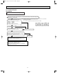
9-3. Relation between main sensor and actuator
<MUZ-GB50>
Discharge temperature thermistor
Indoor pipe temperature thermistor
Defrost thermistor
Fin temperature thermistor
Outdoor heat exchanger temperature
Ambient temperature thermistor
Purpose
Protection
Defrosting Protection
Defrosting
Protection
Protection
Protection
Compressor
LEV
Outdoor
fan motor
R.V. coil
Sensor
Actuator
OB455A--1qxq 06.7.31 2:19 PM Page 15

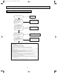
16
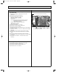
Outline of the function
This air conditioner can memorize the abnormal condition which has occurred once.
Even though LED indication listed on the troubleshooting check table (10-4.) disappears, the memorized failure details
can be recalled.
This mode is very useful when the unit needs to be repaired for the abnormality which doesn't recur.
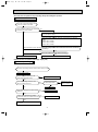
10-2. Failure mode recall function
1. Flow chart of failure mode recall function for the indoor/outdoor unit
Operational procedure
Yes
(Blinks)
No
(OFF)
Yes
No
Releasing the failure mode recall function
Note1.Make sure to release the failure mode recall function once it's set up, otherwise the unit cannot operate properly.
2.If the abnormal condition is not deleted from the memory, the last abnormal condition is kept memorized.
W 2. Blinking pattern when the indoor unit is abnormal:
W 3.Blinking pattern when the outdoor unit is abnormal:
ON
OFF
Beeps
Repeated cycle Repeated cycle
ON
OFF
No beep Beeps
Repeated cycle
2.5-second OFF
Blinking at 0.5-
second interval
2.5-second OFF 3-second ON
Blinking at 0.5-
second interval
Beeps
Repeated cycle
2.5-second OFF
Blinking at 0.5-
second interval
No beep Beeps
Repeated cycle
2.5-second OFF 3-second ON
Blinking at 0.5-
second interval
Repeated cycle
Beeps
Does the left lamp of OPERATION INDICATOR
lamp on the indoor unit blink at the interval of 0.5
seconds?
Blinks: Either indoor or outdoor unit is abnormal.
Beep are emitted at the same timing
as the blinking of the left lamp of
OPERATION INDICATOR lamp. W 2
The cause of abnormality cannot be found because the abnormality doesn't recur.
Setting up the failure mode recall function
Before blinking, does the left lamp of
OPERATION INDICATOR lamp stay ON for 3
seconds?
Stays ON for 3 seconds (without beep):
The outdoor unit is abnormal.
The indoor unit is abnormal.
Check the blinking pattern, and confirm the abnormal point with the indoor unit
failure mode table (Refer to indoor unit service manual.)
Make sure to check at least two consecutive blinking cycles. W 2
Turn ON the power supply.
<
Preparation of the remote controller
>
1 While pressing both OPERATION SELECT
button and TOO COOL button on the remote controller at the same time, press
RESET button.
2 First, release RESET button.
And release the other two buttons after all LCD except the set temperature in
operation display section of the remote controller is displayed after 3 seconds.
Deleting the abnormal memorized condition
1After repairing the unit, recall the failure mode again according to
"Setting up the failure mode recall function" mentioned above.
2Press OPERATE/STOP(ON/OFF) button of the remote controller (the set temperature is displayed)
with the remote controller headed towards the indoor unit.
3Press EMERGENCY OPERATION switch so that the memorized abnormal condition is deleted.
4Release the failure mode recall function according to "Releasing the failure mode recall function"
mentioned above.
Repair the defective parts.
Release the failure mode recall function by the following procedures.
Turn OFF the power supply and turn it ON again.
Press RESET button of the remote controller.
Judgment of indoor/outdoor abnormality
Press OPERATE/STOP(ON/OFF) button of the remote controller (the set temperature
is displayed) with the remote controller headed towards the indoor unit. w1
Indoor unit is normal.
But the outdoor unit might be abnormal because there are some
abnormalities that can't be recalled with this way.
Confirm if outdoor unit is abnormal according to the detailed outdoor
unit failure mode recall function.(Refer to 10-2.2)
The outdoor unit is abnormal.
Check the blinking pattern, and confirm the abnormal point with the
outdoor unit failure mode table (Refer to 10-2.3).
Make sure to check at least two consecutive blinking cycles. W 3
W 1. Regardless of normal or abnormal, a short
beep is emitted once as the signal is received.
OB455A--1qxq 06.7.31 2:19 PM Page 16

17
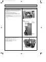
2. Flow chart of the detailed outdoor unit failure mode recall function
Operational procedure
Note1. Make sure to release the failure mode recall function once it's set up, otherwise the unit cannot operate properly.
2. If the abnormal condition is not deleted from the memory, the last abnormal condition is kept memorized.
W2.Blinking pattern when outdoor unit is abnormal:
Yes
(Blinks)
No
(OFF)
ON
OFF
No beep
Beeps
Repeated cycle
2.5-second OFF 3-second ON
Blinking at 0.5-
second interval
No beep Beeps
Repeated cycle
2.5-second OFF 3-second ON
Blinking at 0.5-
second interval
Repeated cycle
W1. Regardless of normal or abnormal, 2 short
beeps are emitted as the signal is received.
Does left lamp of OPERATION INDICATOR lamp
on the indoor unit blink at the interval of 0.5 seconds?
Blinks: The outdoor unit is abnormal.
Beep are emitted at the same
timing as the blinking of the left lamp of
OPERATION INDICATOR lamp. W2
Deleting the abnormal memorized condition
1After repairing the unit, recall the failure mode again according to
"Setting up the failure mode recall function" mentioned above.
2Press OPERATE/STOP(ON/OFF) button of the remote controller (the set temperature is displayed)
with the remote controller headed towards the indoor unit.
3Press EMERGENCY OPERATION switch so that the memorized abnormal condition is deleted.
4Release the failure mode recall function according to "Releasing the failure mode recall function"
mentioned above.
Repair the defective parts.
With the remote controller headed towards the indoor unit, press TOO COOL or TOO
WARM button to adjust the set temperature to 25:. W1
The outdoor unit is normal.
Releasing the failure mode recall function
Release the failure mode recall function by the following procedures.
Turn OFF the power supply and turn it ON again.
Press RESET button of the remote controller.
The outdoor unit is abnormal.
Check the blinking pattern, and confirm the abnormal point with the
outdoor unit failure mode table (Refer to 10-2.3.).
Make sure to check at least two consecutive blinking cycles. W2
Release the failure mode recall function according
to the left mentioned procedure.
Confirm that the remote controller is in the failure mode recall
function.
The outdoor unit might be abnormal.
Confirm if outdoor unit is abnormal according to the following procedures.
OB455A--1qxq 06.7.31 2:19 PM Page 17

18
OFF None (Normal)
2-time flash
3-time flash
4-time flash
5-time flash
6-time flash
7-time flash
8-time flash
Lighting Lighting
Lighting Once
Lighting Once
Lighting Twice
Lighting 3 times
Lighting 4 times
Lighting 9 times
Once Goes
out
Lighting
Lighting
Lighting
Lighting
3 times
Goes
out
4 times Goes
out
Lighting
Lighting
Lighting
Lighting
Lighting
5 times
9-time flash
10-time flash
• Check the connection
of the compressor
connecting wire.
• Refer to 10-6.A
"How to check
inverter / compressor".
• Check the stop valve.
• Replace the outdoor
electronic control
P.C. board.
•Check refrigerant circuit
and refrigerant amount.
• Refer to 10-6.G "Check
of LEV".
• Refer to 10-6.D "Check
of outdoor fan motor".
• Replace the outdoor
electronic control
P.C. board.
•Check refrigerant circuit
and refrigerant amount.
• Refer to 10-6.G "Check
of LEV".
• Reconnect compressor
connector.
• Refer to 10-6.A "How to
check inverter/
compressor."
• Check the stop valve.
•Check refrigerant circuit
and refrigerant amount.
• Check the stop valve.
• Check around outdoor
unit.
• Check outdoor unit air
passage.
• Refer to 10-6.D "Check
of outdoor fan motor".
• Refer to 10-6.B "Check
of outdoor thermistors".
• Refer to 10-6.B "Check
of outdoor thermistors".
When over current protection stop is
continuously performed three times
within 1 minute after the compressor
gets started, or when converter
protection stop or bus-bar voltage
protection stop is continuously
performed three times within 3
minutes after start-up.
When thermistor shorts or opens
during compressor running.
When 28A current flow into intelligent
power module.
When the outdoor heat exchanger
temperature exceeds 70:
during cooling or the indoor gas
pipe temperature exceeds 70:
during heating.
When the fin temperature exceeds
87: during operation.
When the P.C. board temperature
exceeds 70: during operation.
When failure occurs continuously
three times within 30 seconds after
the fan gets started.
When nonvolatile memory data
cannot be read properly.
When the frequency of the
compressor is kept 80Hz or
more and the discharge
temperature is kept under 39:
for more than 20 minutes.
Outdoor power system
Discharge temperature
thermistor
Defrost thermistor
Ambient temperature thermistor
Fin temperature thermistor
P.C. board temperature
thermistor
Outdoor heat exchanger
temperature thermistor
Over current
Discharge temperature
High pressure
Fin temperature
P.C. board temperature
Outdoor fan motor
Nonvolatile memory data
Discharge temperature
--
Abnormal point
(Failure mode / protection)
Condition
Correspondence
Indoor/outdoor
unit failure mode
recall function
LED indication
(Outdoor P.C. board)
LED
1LED
2
When discharge temperature exceeds
116°C during operation.
Compressor can restart if discharge
temperature thermistor reads 100: or
less 3 minutes later.
The left lamp of
OPERATION INDICATOR
lamp (Indoor unit)
NOTE : Blinking patterns of this mode differ from the ones of Troubleshooting check table (10-4.).
MUZ-GB50VA
3. Outdoor unit failure mode table
OB455A--1qxq 06.7.31 2:19 PM Page 18

19
11-time flash
• Check the connecting
wire between outdoor
electronic control
P.C. board and power
board.
• Replace the power
board.
• Check the connecting
wire among electronic
control P.C. board,
noise filter P.C. board
and power board.
• Replace the power
board.
When the communication between
boards protection stop is
continuously performed twice.
Communication error occurs
between the electronic control P.C.
board and power board for more
than 10 seconds.
Current sensor protection stop is
continuously performed twice.
When a short or open circuit is
detected in the current sensor
during compressor operating.
The protection stop of the zero
cross detecting circuit is
continuously performed 10 times.
When zero cross signal cannot be
detected while the compressor is
operating.
When a failure is detected in the
operation of the converter during
operation.
When the bus-bar voltage exceeds
400V or falls to 200V or below
during compressor operating.
When the bus-bar voltage exceeds
400V or falls to 50V or below during
compressor operating.
Communication error
between P.C. boards
Current sensor
Zero cross detecting circuit
Converter
Bus-bar voltage
(1)
Bus-bar voltage
(2)
wEven if this protection stop is
performed continuously three
times, it does not mean the
abnormality in outdoor power
system.
Lighting 6 times
Lighting 7 times
5 times Goes
out
5 times
Goes
out
5 times
6 times
Goes
out
Goes
out
Abnormal point
(Failure mode / protection)
Condition
Correspondence
Indoor/outdoor
unit failure mode
recall function
LED indication
(Outdoor P.C. board)
LED
1LED
2
The left lamp of
OPERATION INDICATOR
lamp (Indoor unit)
NOTE : Blinking patterns of this mode differ from the ones of Troubleshooting check table (10-4.).
MUZ-GB50VA
OB455A--1qxq 06.7.31 2:19 PM Page 19

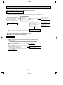
20
Start
Indoor unit
operates.
Outdoor unit
doesn't
operate.
Indoor unit
doesn't receive
the signal from
remote controller.
OPERATION
INDICATOR
lamp on the indoor
unit is flashing on
and off.
Outdoor unit
operates only
in Test Run
operation.
(Refer to 8-3.)
w
Outdoor unit
doesn't
operate
even in
Test Run
operation.
(Refer to 8-3.)
w
Indoor unit
operates, when
EMERGENCY
OPERATION
switch is pressed.
Indoor unit
doesn't operate,
when
EMERGENCY
OPERATION
switch is pressed.
Check room
temperature
thermistor.
Refer to
"Test point
diagram and
voltage".
Refer to 10-6.A
"How to check
inverter/
compressor".
Refer to
"Check of
remote controller
and receiver
P.C. board".
1. Check indoor / outdoor
connecting wire.
(Check if the power
is supplied to the
indoor unit.)
2. Refer to
"Check of indoor
electronic control
P.C. board and indoor
fan motor".
Unit doesn't
operate
normal
operation in
COOL or
HEAT mode.
Refer to 10-6.C
"Check of
R.V. coil".
Left lamp
Flash on and
off at
0.5-second
intervals
Cause:
Indoor/
Outdoor unit
• Mis-wiring or
trouble of
serial signal.
Left lamp
2-time flash
Cause:
Indoor unit
• Trouble of
room temp-
erature/
indoor coil
thermistor
Left lamp
3-time flash
Cause:
Indoor unit
• Trouble of
indoor fan
motor
Left
lamp
5-time flash
Cause:
Outdoor unit
• Outdoor
power
system
abnormality
Left lamp
6-time flash
Cause:
Outdoor unit
• Trouble of
thermistor
in outdoor
unit
Left lamp
7-time flash
Cause:
Outdoor unit
• Trouble of
outdoor
control
system
Refer to 10-6.H
"How to check
mis-wiring
and serial
signal error.
Check room
temperature
thermistor
and indoor
coil thermis-
tor.
Refer to "Test
point diagram
and voltage".
Refer to
"Check of
indoor fan
motor".
Refer to 10-6.A
"How to check
inverter/
compressor".
Refer to 10-6.B
"Check of
outdoor
thermistors".
Replace
inverter P.C.
board or out-
door control
electronic
control P.C.
board.
Left lamp
14-time flash
Cause:
Outdoor unit
• Other
abnormality
Check 10-2.2.
"Flow chart of
the detailed
outdoor unit
failure mode
recall function."
Left lamp
4-time flash
Cause:
Indoor unit
• Trouble of
indoor unit
control
system
Replace the
indoor
electronic
control
P.C. board.
Refer to indoor unit
service manual.
Indoor unit operates.
Outdoor unit doesn't
operate normally.
If blinking of OPERATION
INDICATOR lamp cannot
be checked, it can be checked
with failure mode recall function.
w "Test Run operation" means
the operation within 30 minutes
after EMERGENCY OPERATION
switch is pressed.
All lamps
Flash on and off
at 0.5-second
intervals
Cause:
Indoor unit
• The horizontal
vane is not
installed
correctly.
Refer to
"Check of
installation of
the horizontal
vane".
10-3. Instruction of troubleshooting
OB455A--1qxq 06.7.31 2:19 PM Page 20
Page is loading ...
Page is loading ...
Page is loading ...
Page is loading ...
Page is loading ...
Page is loading ...
Page is loading ...
Page is loading ...
Page is loading ...
Page is loading ...
Page is loading ...
Page is loading ...
Page is loading ...
Page is loading ...
Page is loading ...
Page is loading ...
Page is loading ...
Page is loading ...
Page is loading ...
Page is loading ...
-
 1
1
-
 2
2
-
 3
3
-
 4
4
-
 5
5
-
 6
6
-
 7
7
-
 8
8
-
 9
9
-
 10
10
-
 11
11
-
 12
12
-
 13
13
-
 14
14
-
 15
15
-
 16
16
-
 17
17
-
 18
18
-
 19
19
-
 20
20
-
 21
21
-
 22
22
-
 23
23
-
 24
24
-
 25
25
-
 26
26
-
 27
27
-
 28
28
-
 29
29
-
 30
30
-
 31
31
-
 32
32
-
 33
33
-
 34
34
-
 35
35
-
 36
36
-
 37
37
-
 38
38
-
 39
39
-
 40
40


Mitsubishi Electronics MUZ-GB50VA User manual
- Category
- Split-system air conditioners
- Type
- User manual
Ask a question and I''ll find the answer in the document
Finding information in a document is now easier with AI
Related papers
-
Mitsubishi Electronics MS-AWA User manual
-
Mitsubishi MUZ-FD12NA User manual
-
Mitsubishi Electric MSZ-GE42VA User manual
-
-
-
 Mitsubishi Electronics MXZ-24UV User manual
-
-
 Mitsubishi Electronics MUY-GE09NA User manual
-
 Mitsubishi Electronics MUZ-D36NA User manual
-
Mitsubishi MSZ-GA25VA User manual


Other documents
-
-
Mitsubishi Electric MUZ-WR24NA Owner's manual
-
Mitsubishi MS-GD10ND User manual
-
-
-
-
LG LS121HSV Owner's manual
-
-
DKS User manual
-
Hitachi RAS-(4-12)HNC(1)(E) User manual