Page is loading ...

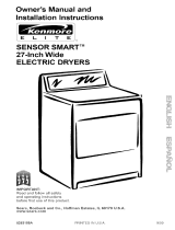
Owner's Manual and
Installation Instructions
27-Inch Wide
ELECTRIC DRYERS
='= ==,_ =,.=
IMPORTANT:
Read and follow all safety
and operating instructions
before first use of this product.
Your dryer may look different
from the dryer shown.
Sears, Roebuck and Co., Hoffman Estates, IL 60179 U.S.A.
PART NO. 3405602
PRINTED IN U.S.A.
i

BEFORE USING YOUR NEW DRYER 2
SEARS ELECTRIC DRYER WARRANTY 3
IMPORTANT SAFETY INSTRUCTIONS 4
INSTALLATION INSTRUCTIONS
5
OPERATING YOUR DRYER
LAUNDRYTIPS
25
32
CARING FOR YOUR DRYER 34
TROUBLESHOOTING 38
SEARS MAINTENANCE AGREEMENT 4O
Please read this manual,, It will help
you install and operate your new
Kenmore dryer in the safest and most
economical way.
For ,more information about the care
and operation of Kenmore appliances
call your nearest Sears store. You will
need the complete model and serial
numlbers when requesting information.
Your dryer's model and serial numbers
are located on the Model and Serial
Number Plate.
Use the space below to record the model
number and serial number of your new
Kenmore Dryer.
Model No.
Serial No.
Date of Purchase
Keep this book and your Sears
Salescheck (receipt) in a safe place
for future reference.

FULL 1-YEAR WARRANTY
ON MECHANICAL AND
ELECTRICAL PARTS
For one year from the date of purchase,
when this dryer is installed and operated
according to the instructions in the Owner's
Manual, Sears will repair or replace any
mechanical or electrical parts in this dryer,
if defective in material or workmanship.
This warranty does not cover service
calls to correct improper installation,
including dryers that have been vented
with plastic or flexible foil.
If the dryer is subjected to other than
private family use, the above warranty
coverage is effective for only 90 days.
WARRANTY SERVICE IS AVAILABLE
BY CONTACTING THE NEAREST
SEARS SERVICE CENTER IN THE
UNITED STATES.
This warranty applies only while this
product is in use in the United States.
This warranty gives you specific legal
rights, and you may also have other
rights which vary from state to state.
Sears Roebuck and Co., Dept. 817WA,
Hoffman Estates, IL 60179.
NOTE: Proper installation to comply
with the dryer's warranty is found in
the Installation Instructions of this
Owner's Manual.
Your safety and the safety of others is very important.
We have provided many important safety messages in this manual
and on your appliance. Always read and obey all safety messages.
This is the safety alert symbol.This symbol alerts
you to hazards that can kill or hurt you and others.
All safety messages will be preceded by the safety
alert symbol and the word "DANGER" or "WARNING:'
These words mean:
You wil___!lbe killed or seriously
injured if you don't follow
instructions.
You can be killed or seriously
injured if you don't follow
instructions.
All safety messages will identify the hazard, tell you how to reduce the
chance of injury, and tell you what can happen if the instructions are
not followed.
3

YOUR SAFETY IS IMPORTANT TO US.
WARNING" To reduce the risk of fire,
electric shock, or injury to persons
when using your dryer, follow basic
precautions, including the following:
• Read all instructions before using
the dryer.
• Do not dry articles that have been
previously cleaned in, washed in, soaked
in, or spotted with gasoline, dry-cleaning
solvents, other flammable or explosive
substances as they give off vapors that
could ignite or explode.
• Do not allow children to play on or in
the dryer. Close supervision of children
is necessary when the dryer is used
near children.
• Before the dryer is removed from
service or discarded, remove the door
to the drying compartment.
• Do not reach into the dryer if the drum
is moving.
• 13onot install or store this dryer where
it will be exposed to the weather.
• Do not tamper with controls.
• Do not repair or replace any part of the
dryer or attempt any servicing unless
specifically recommended in the Owner's
Manual or in published user-repair
instructions that you understand and
have the skills to carry out.
• Do not use fabric softeners or products
to eliminate static unless recommended
by the manufacturer of the fabric ,,;oftener
or product.
• Do not use heat to dry articles containing
foam rubber or similarly textured rubber-
like materials.
• Clean lint screen before or after each
load.
• Keep area around the exhaust opening
and adjacent surrounding areas free from
the accumulation of lint, dust, and dirt.
• The interior of the machine and exhaust
duct should be cleaned periodically by
qualified service personnel.
SAVE THESE INSTRUCTIONS
IMPORTANT: Observe all governing codes and ordinances.
\

INSTALLATION OVERVIEW
For a complete list of tools and parts
needed, see pages 5-7.
A. SELECT LOCATION
FOR YOUR DRYER (pgs. 8-9)
Standard Installation (p. 8)
, _--.--------------
Recessed Area/
Closet Installation Instructions (p. 9)
H j ....
i
B. INSTALL LEVELING LEGS (p. 10)
Tools Needed: Parts Needed:
J
Adjustable
wrench
Two corner posts
(from dryer carton)
Flashlight (optional
depending on installation)
4 leveling legs (supplied with dryer)

(.3.MAKE ELECTRICAL CONNECTION (pgs. 11-19)
If using a power cord:
Tools Needed:
V4-1nch nut
driver (shown)
or socket wrench
#2 Phillips head
screwdriver
Flashlight (optional
depending on installation)
Parts Needed:
S_lrainreliel
New 3- or 4-wire, 30-amp.
U.L.-listed power supply
cord kit (includes strain relief)
If making a direct wire connection:
Tools Needed:
Parts Needed:
V4-1nch nut
driver (shown)
or socket wrench
#2 Phillips head
screwdriver
Wire stripper
Flashlight (optional
depending on installation)
3- or 4-wire,
flexible armored
or non-metallic
sheathed copper cable
(with grounding wire)
Strain relief
T
y

D. CONNECT EXHAUST (pgs. 19-23)
!
'i
i
C
i
Tools Needed:
Parts Needed:
Tin snips Duct tape
Flashlight (optional
depending on installation)
Flat-bladed
screwdriver
4-Inch heavy or
flexible metal vent
4-Inch metal elbow(s)
(optional depending
on installation)
4-Inch outlet (4) 4-Inch
exhaust hood diameter clamps
f

A. SELECT LOCATION
FOR YOUR DRYER
Selecting the proper location
for your dryer makes installation
easier and gives you the best
drying performance.
STANDARD INSTALLATION
Check location where dryer will be installed.
Proper installation is your responsibility.
Make sure you have everything necessary
for correct installation including proper
floor support, a level floor, and a separate
30-amp. fuse.
* Protect dryer from the weather. Proper
operation of dryer cycles requires
temperatures above 45°F. At lower
temperatures, the dryer may not shut
cff at the end of automatic cycles.
Drying times will be extended.
Explosion Hazard
Keep flammable materials and vapors,
such as gasoline, away from dryer.
Place dryer at least 18 inches above
the floor for a garage installation.
Failure to follow these instructions
can result in death, explosion, or fire.
• Check code requirements. Some
codes limit or do not permit installation
of clothes dryers in garages, closets,
mobile homes, or sleeping quarters.
Contact your local building inspector.
Separate
30-amp. fuse.
Grounded receptacle:
Within 2 feet of either
side of dryer.
Support: Floor must be
sturdy enough to support
a total weight of 175
pounds (includes dryer
and load weight).
y
Level floor: Maximum
allowable slope under entire
dryer- 1 inch.

RECESSED AREA/CLOSET
INSTALLATION INSTRUCTIONS
Check governing codes and ordinances.
This dryer may be installed in a recessed
area or closet.
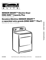
PRODUCT DIMENSIONS
Location must be large enough to fully
open dryer door.
Confined or Recessed Area Installation
Exhausting the dryer outside is recom-
mended. The moisture and lint indoors
may cause:
• Lint to gather inside and around the
dryer and be a fuel for a fire.
• Moisture damage to woodwork, furni-
ture, paint, wallpaper, carpet, etc.
• Housecleaning problems and possible
health problems.
Recessed installation that is not
exhausted outside must use Exhaust
Deflector Kit Part No. 3391278. This
kit is available at your local Sears store
or Sears Service Center.
Closet Installation
WARNING: To reduce the risk of fire,
this appliance must be exhausted
outdoors when installed in a closet.
NOTE: No fuel burning appliances
may be installed in the same closet
as a dryer.
271/2"
OlO
2?'-d
Front View Side View
(Door Not Shown) (Door Shownl
_(-**.51/z -
FrontView
(DoorWithVent)
MINIMUM INSTALLATIONSPACING. Closet installation MIJ_r be exhausted outside.
"Additional clearances for waft, door and floor moldings may be required. _' ctearaoce
is acceptable but not recommended.
** Opening is minimum for closet door. Louvered doorwith equivalent air
openings is acceptable.
*** Additional space is needed when external exhaust elbow is used• Can be 0" clearance
when house exhausting is lined up directly with dryer exhaust.
3"
3"
,,The installation spacing is in inches
and is the minimum allowable.
• Additional spacing should be
considered for ease of installation
and.,servicing.
• If closet door is installed, the
minimum air openings in top and
bottom are required. Louvered doors
with equivalent air openings in top
and bottom are acceptable.
• Closet installation must be exhausted
outside. Other installations must use at
least the minimum dimensions indicated.
4 _
i

B. INSTALL LEVELING LEGS
Leveling your dryer correctly will
reduce operating noise and provide
improved drying performance.
S'rEP 1. Take two of the cardboard
corners from the carton. Place them on
the floor in back of the dryer.
STEP 2. Firmly grasp the body of the
dryer (not the top or console panel).
Gently lay dryer on the cardboard
corners.
STEP 5. Now stand the dryer up and
move it close to its final location. Leave
enough room to connect the exhaust
vent.
STEP 6. Check levelness of dryer by
placing a level on top of the dryer, first
side-to-side; then front-to-back.
STEP 3. With one of the legs in hand,
check the ridges for a diamond marking.
STEEp4. Start to screw the legs into the
holes by hand. Use a wrench to finish
turning the legs until diamond marking
is no longer visible. This is when we
recommend you start checking the
dryer for levelness. Further adjustment
may' be necessary.
_o
STEP 7. If dryer is not level, prop the
dryer up using two stacked cardboard
corner posts. Use a wrench to adjust
the legs up or down.
.I
I
I
NOTE: It may be necessary to level
the dryer again after it is moved into
its final position.
F

C. MAKE ELECTRICAL
CONNECTION
It is your responsibility:
• To contact a qualified electrical installer.
. TO assure that the electrical installation
i._;adequate and in conformance with
the National Electrical Code, ANSI/
NFPA 70-latest edition and all local
codes and ordinances.
Copies of the code standards listed
above may bE;obtained from:
National Fire Protection Association
Batterymarch Park
Quincy, Massachusetts 02269
ELECTRICAL REQUIREMENTS
The proper electrical connection
ensures a safe installation that
meets local code requirements.
A three-wire or four-wire, single
phase 120/240-volt, 60-Hz., AC-only,
electrical supply (or three-wire or
four-wire, 120/208-volt if specified on
serial/rating plate) is required on a
separate 30-ampere circuit, fused on
both sides of the line. A time-delay fuse
or circuit breaker is recommended.
This dryer is manufactured with the
3-wire, frame-grounding conductor
connected to the NEUTRAL (center)
of the wiring harness of the terminal
block. Do not have a fuse in the
neutral or grounding circuit. A fuse
in the neutral or grounding circuit
could result in an electrical shock.
Use a 4-conductor cord when the
dryer is installed in a mobile home or
an area where local codes do not
permit grounding through the neutral.
ELECTRICAL CONNECTION OPTIONS
If Your Home Has:
A 3-wire electrical
receptacle
(NEMA Type 10-30R)
And You Will Be Go To
Connecting To: Page
A U.L.-listed, 120/240-volt
minimum, 30-amp., dryer
power supply cord*
3-wire direct
A fused disconnect or
circuit breaker box.*
A 4-wire electrical
receptacle
(NEMA Type 14-30R)
A U.L-listed, 120/240-volt
minimum, 30-amp., dryer
power supply cord.
4-wire direct
J
A fused disconnect or
circuit breaker box.
"If local codes do not permit the connection of a frame-grounding conductor
to the neutral wire, see the instructions on page 15.
12-1.
13-11.
16-111.
18-IV.
F
11

12
I. THREE-WIRE ELECTRICAL
CONNECTION TO RECEPTACLE
Use a 3-wire power supply cord:
Electrical Shock Hazard
Turn power supply off before
connecting cord.
Use a new 30-ampere power
supply cord.
Plug into a grounded outlet.
Failure to follow these instructions
can result in death, fire, or
electrical shock.
Local codes may permit the use of
a U.L.-listed, 120/240-volt minimum,
30-ampere, dryer power supply cord
kit (pigtail). Power supply cord should
be type SRD or SRDT and be at least
four feet long.. The wires that connect
to the dryer must end with ring terminals
or spade terminals with upturned ends.
Spadeterminals_ ,__
withupturnedends
_ Thisbladeconnected Ring
NEI_ to thisco_ s
strainrelief (white orcenter)
Three-wire power supplycord
The power supply cord must have three,
No.-10 copper wires to match a three-
wire receptacle of NEMA Type 10-30R.
I_ hree-wire
receptacle
• (NEMAType
10-30R)
Do not use an extension cord with
this dryer.
Do not connect plug end of power
supply cord into a live receptacle
before connecting power supply cord
to dryer terminal block.
GROUNDING INSTRUCTIONS
This appliance must be grounded.
In the event of malfunction or break-
down, grounding will reduce the risk
of electric shock by providing a path
of least resistance for electric current.
The power supply cord must be plugged
into an appropriate outlet that is properly
installed and grounded in accordance
with all local codes and ordinances.
WARNING: Improper connection of the
equipment-grounding conductor can
result in a risk of electric shock. Check
with a qualified electrician or serviceman
if your are in doubt as to whether the
appliance is properly grounded.
Do not modify the plug on the power
supply cord. If it will not fit the outlet,
have a proper outlet installed by a
qualified electrician.
STEP 1. Turn power supply off.
STEP 2. Remove hold-down screw
and terminal block cover.
Hold-downscrew Terminalblockcover

STEP 3. Attach a 3/4-inch, U.L.-listed,
strain relief to the hole below terminal
block opening. Strain relief should have
a tight fit with dryer cabinet and be in a
horizontal position. Put the power supply
cord through the strain relief.
STEP 4. Loosen or remove terminal block
screws. Connect the neutral wire (white
or center) of power supply cord under
the center screw of the terminal block.
STEP 5. Connect the other two wires
to outer terminal block screws. Tighten
all terminal block screws firmly.
Exlernalground
connector
Centersilver-colored
terminalblockscrew
White
neutral
wire
Neutral
grounding wire 3/4",U.L.-listed,
(green/yellow) strain relief
3-Wire Connection with
Frame-Grounding Conductor
S'FEP 6. Tighten the strain relief screws.
STEP 7. Insert tab of terminal block
cover into slot of the dryer rear panel.
Secure cover with hold-down screw.
If local codes do not permit the
connection of a frame-grounding
conductor to the neutral wire, see
the instructions on page 15.
Otherwise, proceed with Exhaust
Installation. See "CONNECT
E×HAUST" on page 19.
II. THREE-WIRE ELECTRICAL
CONNECTION (DIRECT WIRE)
Prepare cable as directed:
Electrical Shock Hazard
Turn power supply off before
connecting wires.
Use 10 gauge solid copper wire.
Electrically ground dryer.
Failure to follow these instructions
can result in death, fire, or
electrical shock.
The dryer can be connected directly
to fused disconnect or circuit breaker
box with three-wire, flexible armored
or non-metallic sheathed copper cable
(with grounding wire). All current-carrying
wires must be insulated.
A conduit connector must be installed at
junction box. Allow four feet of slack in the
line so dryer can be moved if servicing
is ever necessary.
GROUNDING INSTRUCTIONS
This appliance must be connected to
a grounded metal, permanent wiring
system; or an equipment-grounding
conductor must be run with the circuit
conductors and connected to the
equipment-grounding terminal or
lead on the appliance.
STEP 1. Turn power supply off.
STEP la. Strip 31/2inches of outer
covering from end of cable. If using
3-wire cable with grounding wire, cut
the bare wire even with outer covering.
13

STEP lb. Cut 1 inch of insulation from
the end of each insulated wire. Shape
the end of each wire into a "U" shaped
hook.
STEP 2. Remove hold-down screw and
terminal block cover.
Terminalblockcover
Hold-downscrew
STEP 3. Attach a 3/4-inch, U.L.-listed,
strain relief to the hole below terminal
block opening. Strain relief should have
a tight fit with dryer cabinet and be in a
horizontal position. Put the direct wire
cable through the strain relief.
STEP 4. Loosen or remove terminal block
screws. Connect the neutral wire (white
or center) of direct wire cable under the
center screw of the terminal block.
STEP 4a. Place the hook-shaped end
of the wire over the terminal block screw.
The open side of the hook should face
to the right. Squeeze hook end of wire
together to form a loop.
STEP 5. Connect the other two wires
to outer terminal block screws using the
same method(s) described in STEP 4a.
Tighten all terminal block screws firmly.
STEP 6. "lqghten the strain relief screws.
STEP 7. Insert tab of terminal block
cover into slot of the dryer rear panel.
Secure cover with hold-down screw.
If local codes do not permit the
connection of a frame-grounding
conductor to the neutral wire, see
the instructions on page 15.
Otherwise, proceed with Exhaust
Installation. See "CONNECT
EXHAUST" on page 19.
Externalground
connector_
colored
terminalblockscrew
Neutral grounding
wire (green/yell0w)
White
neutral
wire
3/4",U.L-listed,
strainrelief
14
3-Wire Connection with Direct Wire
and Frame-Grounding Conductor

ALTERNATECONNECTION:
If local codes do not permit the
connection of a frame-grounding
conductor to the neutral wire:
STEP 1. Make sure the power supply to
the dryer is off.
STEP 2. Make sure the power supply
cord or direct wire cable is in place (see
steps 1-3 on pages 12-13 for power cord
connections or steps 1-3 on pages 13-14
for ,direct wire connection).
STE=P3, Remove the neutral grounding
wire (green/yellow wire) from external
grounding connector screw. Loosen or
remove terminal block screws. Connect
neutral grounding wire and the neutral
wire (white or center) of power supply
cord or direct wire cable under the center
screw of the terminal block.
STEP 4, Connect the other two wires
to outer terminal block screws. Tighten
all terminal block screws firmly.
STEP 5, Tighten the strain relief screws.
STEP 6, Insert tab of terminal block
cover into slot of the dryer rear panel.
Secure cover with hold-down screw.
STEP 7, Connect separate copper
grounding wire from external ground
connector to an adequate ground. If
codes permit and a separate grounding
wire is used, it is recommended that a
qualified electrician determine that the
grounding path is adequate.
Proceed with Exhaust Installation.
See "CONNECT EXHAUST" on
page 19.
External
ground
connector
Neutral
groundingwire
(green/yellow)
Groundingpath
determinedbya
qualiliedelectrician
Alternate 3-Wire Connection with
External-Grounding Conductor
15

36
III. MAKE FOUR-WIRE
ELECTRICAL CONNECTION
TO RECEPTACLE
Use a 4-wire power supply cord:
Electrical Shock Hazard
Turn power' supply off before
('onnecting cord.
Use a new 30-ampere power
supply cord.
Plug into a grounded outlet.
Failure to follow these instructions
(;an result indeath, fire, or
electrical shock.
Local codes may permit the use of
a U.L.-listed, 120/240-volt minimum,
30-ampere, dr_,er power supply cord
kit (pigtail). Power supply cord should
be "typeSRD or SRDT and be at least
fou="feet long. The wires that connect
to the dryer must end with ring terminals
or spade terminals with upturned ends.
NEUTRAL NEUTRAL
/ 3/4",U.L.-listed, (white)
J strainrelief \(_
prong wire (green) terminals
Four-wire power supply cord
(Mobile home or other
four-wire installations)
For mobile homes or other four-wire
inst,allations, the power supply cord
must have four, No.-10 copper wires
and match a four-wire receptacle
of I_!EMA Type 14-30R. The fourth
wire. (grounding conductor) must be
identified with a green cover or bare
copper wire and the neutral conductor
by a white cover.
Four-wire receptacle
(NEMAType 14-30R)
Do not use an extension cord with
this dryer.
Do not connect plug end of power
supply cord into a live receptacle before
connecting power supply cord to dryer
terminal block.
GROUNDING INSTRUCTIONS
This appliance must be grounded.
In the event of malfunction or break-
down, grounding will reduce the risk
of electric shock by providing a path
of least resistance for electric current.
The power supply cord must be plugged
into an appropriate outlet that is properly
installed and grounded in accordance
with all local codes and ordinances.
WARNING: Improper connection of the
equipment-grounding conductor carl
result in a risk of electric shock. Check
with a qualified electrician or serviceman
if your are in doubt as to whether the
appliance is properly grounded.
Do not modify the plug on the power
supply cord. If it will not fit the outlet,
have a proper outlet installed by a
qualified electrician.
STEP 1. Turn power supply off.
STEP 2. Remove hold-down screw
and terminal block cover.
Hold-downscrew Terminalblockcover

STEP 3. Attach a 3/4-inch, U.L.-listed,
strain relief to the hole below terminal
block opening. Strain relief should have
a tight fit with dryer cabinet and be in a
horizontal position. Put the power supply
cord through the strain relief.
STEP 4. Remove the center terminal
block screw. Remove the neutral ground-
ing wire (green/yellow wire) from extemal
grounding screw.
Externalground
connector
Centersilver-colored
terminalblockscrew
STEP 5. Connect neutral grounding wire
and the neutral wire (white) of power
supply cord under the center screw of
terminal block.
STEP 6. Connect the other two insulated
wires to outer terminal block screws.
STEP 7. Connect the green, grounding
wire from the power supply cord to the
external grounding conductor screw.
Tighten all terminal block screws firmly.
STEP 8. Tighten the strain relief screws.
STEP 9. Insert tab of terminal block
cover into slot of the dryer rear panel.
Secure cover with hold-down screw.
Proceed with Exhaust Installation.
See "CONNECT EXHAUST" on
page 19.
Green/yellowwire
ofharness
External
ground
connector
Centersilver-
coloredterminal
:kscrew
Whiteneutral
wire
Greenwire
ofpowersupply
cordorbare
copperwire
Neutral
groundingwire
(green/yellow)
3/ l!
/,, U.L.-listed,
strainrelief
4-Wire Connection with
Frame-Grounding Conductor
17

IV. FOUR-WIRE ELECTRICAL
CONNECTION (DIRECT WIRE)
Prepare cable as directed:
Electrical Shock Hazard
1"urn power supply off before
connecting wires.
Use 10 gauge solid copper wire.
ElectricaUy ground dryer.
Failure to follow these instructions
can result in death, fire, or electrical
shock.
The dryer can be connected directly
to fused disconnect or circuit breaker
box with four-wire flexible armored or
non-metallic sheathed copper cable
(with grounding wire). All current-carrying
wires must be insulated. The grounding
wire may be bare.
A conduit connector must be installed
at junction box. Allow four feet of slack
in the line so dryer can be moved if
serJicing is ever necessary.
GROUNDING INSTRUCTIONS
This appliance must be connected to
a grounded metal, permanent wiring
system; or an equipment-grounding
conductor must be run with the circuit
conductors and connected to the
equipment-grounding terminal or
lead on the appliance.
STE'P 1. Turn power supply off.
STEP la. Strip 5 inches of outer
covering from end of cable. Leave
bare grounding wire at 5 inches.
STEP lb. Cut 11/2inches from
3 remaining insulated wires. Strip
insulation back 1 inch. Shape the end
of each wire into a "U" shaped hook.
STEP 2. Remove hold-down screw
and terminal block cover.
Hold-downscrew Terminalblockcover
STEP 3. Attach a 3/4-inch, U.L.-listed,
strain relief to the hole below terminal
block opening. Strain relief should have
a tight fit with dryer cabinet and be in a
horizontal position. Put the direct wire
cable through the strain relief.
STEP 4. Remove the center terminal
block screw. Remove the neutral ground-
ing wire (green/yellow wire) from external
grounding screw.
Externalground Centersilver-colored
connector terminalblockscrew
Green/yellowwire
ofharness

STI-P 5. Connect neutral grounding wire
and the neutral wire (white or center) of
direct wire cable under the center screw
of terminal block.
Centersilver-colored
terminalblockscrew
External ground
connector
Whiteneutralwire
Barecopperwire Neutral
groundingwire
3/_,,,U.L.-listed, (green/yell0w)
strainrelief
4-Wire Connection with Direct Wire
;and Frame-Grounding Conductor
STEP 6. Place the hook-shaped end of
the wire over the terminal block screw.
The open side of the hook should face
to the right. Squeeze hook end of wire
together to form a loop.
STEP 7. Connect the other two wires
to outer terminal block screws. Use the
same method described in STEP 6.
STEP 8. Connect the direct wire cable
(bare) grounding wire to the external-
grounding conductor screw. Tighten all
terminal block screws firmly.
STEP 9. Tighten the strain relief screws.
STEP 10. Insert tab of terminal block
cover into slot of the dryer rear panel.
Secure cover with hold-down screw.
Proceed with Exhaust Installation.
See "CONNECT EXHAUST" on
this page.
D. CONNECT EXHAUST
A properly exhausted dryer will give
you the shortest drying time, lower
your utility bill, and extend the life of
the dryer.
Fire Hazard
Use a heavy metal vent.
Do not use a plastic vent.
Do not use a metal foil vent.
Failure to follow these instructions
can result in death or fire.
• Replace plastic exhaust vent with
heavy metal or flexible metal vent.
• Do not use non-metal flexible vent,
metal vent that is smaller than four
inches in diameter, or exhaust hoods
with magnetic latches.
• Do not exhaust dryer into a chimney,
furnace cold air duct, attic or crawl space,
or any other duct used for venting.
° Do not install flexible metal vent in
enclosed walls, ceilings, or floors,
• If using an existing exhaust system,
disconnect vent from the dryer and
clean one section at a time until you
reach the exhaust hood. To clean out
lint, you can use the hose attachment
on your vacuum or, use a pole or wire
with a feather duster or rag attached.
• Make sure exhaust hood is not plugged
with lint. Follow the instructions in this
section to reinstall your vent system.
19

20
ROUTE THE VENT
Typical installations exhaust from the
rear of the d.ryer.
Avoid pushing the dryer tightly against
a 'wall. This can crush or kink the vent.
Use the straightest path you can, where
possible. Avoid 90 ° turns.
Rear exhaust installations for standard
offset connections - (see pgs. 21-22)
Rear exhaust installations for offset
connections with close clearances-
(see: p. 23)
This dryer may be converted to exhaust
out the right or left side or through the
bottom. To convert the dryer, the following
kits must be used.
Exhaust Kit No. 279818 (white)
Exhaust Kit No. 279819 (almond)
Exhaust Kit No. 279820 (ebony)
Follow the instructions in the kit to
avoid operational and personal hazards.
These kits are available at your local
Sears store or Sears Service Center.
Typical installations for left or right side
exhausting
Typical installations for bottom exhausting
G
/