PEAK-System PCAN-GPRS Link Operating instructions
- Category
- GPS receiver modules
- Type
- Operating instructions
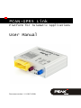
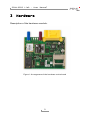
PEAK-System PCAN-GPRS Link is a platform for telematic applications that enables the recording and forwarding of vehicle data. Thanks to its dual-core ARM7 (core) and ARM9 (GPRS) system, it can handle DTCO and FMS data, as well as OBD-2 data via CAN. It also supports the evaluation of FMS and Bus FMS data (Fleet Management Standard), producing consumption-related vehicle data. Additionally, the GPS module can be used to determine location and output the direction of travel. The PCAN-GPRS Link has ECE type approval (E1), which guarantees its problem–free use in vehicles.
PEAK-System PCAN-GPRS Link is a platform for telematic applications that enables the recording and forwarding of vehicle data. Thanks to its dual-core ARM7 (core) and ARM9 (GPRS) system, it can handle DTCO and FMS data, as well as OBD-2 data via CAN. It also supports the evaluation of FMS and Bus FMS data (Fleet Management Standard), producing consumption-related vehicle data. Additionally, the GPS module can be used to determine location and output the direction of travel. The PCAN-GPRS Link has ECE type approval (E1), which guarantees its problem–free use in vehicles.


-
 1
1
-
 2
2
-
 3
3
-
 4
4
-
 5
5
-
 6
6
-
 7
7
-
 8
8
-
 9
9
-
 10
10
-
 11
11
-
 12
12
-
 13
13
-
 14
14
-
 15
15
-
 16
16
-
 17
17
-
 18
18
-
 19
19
-
 20
20
-
 21
21
-
 22
22
-
 23
23
-
 24
24
-
 25
25
-
 26
26
-
 27
27
-
 28
28
-
 29
29
-
 30
30
-
 31
31
-
 32
32
-
 33
33
-
 34
34
-
 35
35
-
 36
36
-
 37
37
-
 38
38
-
 39
39
-
 40
40
-
 41
41
-
 42
42


PEAK-System PCAN-GPRS Link Operating instructions
- Category
- GPS receiver modules
- Type
- Operating instructions
PEAK-System PCAN-GPRS Link is a platform for telematic applications that enables the recording and forwarding of vehicle data. Thanks to its dual-core ARM7 (core) and ARM9 (GPRS) system, it can handle DTCO and FMS data, as well as OBD-2 data via CAN. It also supports the evaluation of FMS and Bus FMS data (Fleet Management Standard), producing consumption-related vehicle data. Additionally, the GPS module can be used to determine location and output the direction of travel. The PCAN-GPRS Link has ECE type approval (E1), which guarantees its problem–free use in vehicles.
Ask a question and I''ll find the answer in the document
Finding information in a document is now easier with AI
Related papers
-
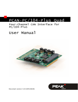 PEAK-System PCAN-PC/104-Plus Quad Operating instructions
-
 PEAK-System PCAN-PC/104-Plus Quad Operating instructions
-
PEAK PCAN-Router Pro FD User manual
-
-
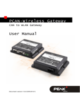 PEAK-System PCAN-Wireless Gateway Operating instructions
-
 PEAK-System PCAN-OBD-2 Viewer Bedienungsanleitung Operating instructions
-
 PEAK-System PCAN-Wireless Gateway Operating instructions
-
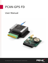 PEAK-System PCAN-GPS FD Operating instructions
-
 PEAK-System PCAN-Router DR Operating instructions
-
 PEAK-System PCAN-Router DR Operating instructions


Other documents
-
PEAK PCAN-GPRS Link User manual
-
-
-
-
-
-
OTC 3109N User manual
-
VDO DTCO 4.0 User manual
-
Hembry Creek SH-BLOX-ST36DW Installation guide
-