
Read these instructions completely before beginning
installation. Failure to follow them could cause a heater
malfunction resulting in serious injury and/or property
damage.
WARNING: All electric heaters have hot and arcing
or sparking parts inside. Do not use it in areas where
gasoline, paint or ammable liquids are or are stored.
This replace meets the construction and safety stan-
dards of H.U.D. for application in manufactured homes
when installed according to these instructions.
INSTALLER: Leave this manual with the appliance.
CONSUMER: Retain this manual for future reference.
For more information, visit www.desatech.com
ELECTRIC FIREPLACE/INSERT
26" MODELS CGEF26B, VEF26B, ES301
32" MODELS CGEF32D, VEF32B
SAFETY INFORMATION AND INSTALLATION MANUAL
Patent No. 7,219,456 B1

www.desatech.com
120927-54C2
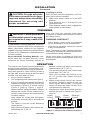
SAFETY
WARNING: Improper installa-
tion, adjustment, alteration, ser-
vice or maintenance can cause
injury or property damage. Refer
to this manual. For assistance or
additional information, consult
a qualied installer.
CAUTION: Do not expose the
heater to the elements (such as
rain, etc).
Do not place clothing or other
ammable material on or near
rebox. Never place any objects
on the replace.
Carefully supervise young chil-
dren when they are in the room
with replace.
Fireplace becomes very hot
when running. Keep children and
adults away from hot surfaces to
avoid burns or clothing ignition.
Fireplace will remain hot for a
time after shutdown. Allow sur-
faces to cool before touching.
Do not install replace directly
on carpet or similar surface
which may restrict air circulation
beneath unit.
When using electrical heaters, basic precau-
tions should always be followed to reduce
the risk of re, electric shock and injury to
persons, including the following:
1. Read all instructions before using this
heater.
2. Keep combustible materials, such as
furniture, pillows, bedding, papers, clothes
and curtains away from front of heater.
3. This heater is hot when in use. To avoid
burns, do not let bare skin touch hot surfac-
es. The grill directly in front of heater outlet
becomes hot during heater operation.
4. Extreme caution is necessary when any
heater is used by or near children or inva-
lids and whenever heater is left operating
and unattended.
5. Always unplug heater when not in use.
6. Do not operate any heater with a damaged
cord or plug or if heater malfunctions or
has been dropped or damaged in any way.
Return heater to authorized service facility
for examination, electrical or mechanical
adjustment or repair.
7. Do not use outdoors.
8. This heater is not intended for use in
bathrooms, laundry areas and similar
indoor locations. Never locate heater
where it may fall into a bathtub or other
water container.
9. Do not run cord under carpeting. Do not
cover cord with throw rugs, runners or the
like. Arrange cord away from trafc area
and where it will not be tripped over.
10. To disconnect heater, turn controls to the
OFF before removing plug from outlet.
11. Do not insert or allow foreign objects to
enter any ventilation or exhaust opening
as this may cause an electric shock or re
or damage the heater.
12. To prevent possible re, do not block air
intakes in any manner. Do not use on soft
surfaces, like a bed, where openings may
become blocked.
13. Always use properly grounded fused and
polarized outlets.
TABLE OF CONTENTS
Safety .................................................................. 2
Listing Approvals ................................................. 3
Product Dimensions ............................................ 3
Product Identication ........................................... 4
Unpacking and Testing ........................................ 4
Locating Fireplace ............................................... 4
Installation ........................................................... 5
Finishing .............................................................. 7
Operation ............................................................. 7
Cleaning and Maintenance .................................. 8
Technical Service............................................... 12
Replacement Parts ............................................ 12
Troubleshooting ................................................. 13
Wiring Diagram .................................................. 14
Accessories ....................................................... 15
Parts .................................................................. 16
Warranty ..............................................Back Cover

www.desatech.com
120927-54C 3
SAFETY
Continued
14. A heater has hot and arcing or sparking
parts inside. Do not use it in areas where
gasoline, paint or ammable liquids or
vapors are used or stored.
15. Use this heater only as described in this
manual. Any other use not recommended
by the manufacturer may cause re, elec-
tric shock or injury to persons.
16. Avoid the use of an extension cord be-
cause the extension cord may overheat
and cause a risk of re. However, if you
have to use an extension cord, the cord
should be No. 14 AWG minimum size and
rated not less than 1875 WATTS.
17. Always use ground fault protection where
required by electrical codes.
Description: 26" and 32" Fireplace/Inserts
Voltage: 120
Watts: 1500
Amps: 15 Amp
Grounded Circuit
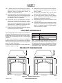
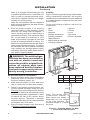
PRODUCT DIMENSIONS
Figure 1 - Heater Dimensions
Note: This heater must be electrically wired and
grounded in accordance with local codes or, in
the absence of local codes, with National Electric
Code ANSI/NFPA 70-latest edition or the Cana-
dian Electric Code, CSA C22.1 as appropriate.
18. Always disconnect power before perform-
ing any cleaning, maintenance or reloca-
tion of heater.
19. To prevent a possible re, do not burn
wood or other materials in this heater.
20. To prevent electric shock or re, always
use a certified electrician should new
circuits or outlets be required.
21. When transporting or storing heater, keep
in a dry place.
22. Control panel door gets hot during heater
operation. Open door by pressing on right
corner. A spring magnet will disengage.
Pull door down to open.
LISTING APPROVALS
This heater has been tested in accordance
with the CSA Standards for xed and location-
dedicated electric room heaters in the United
States. All components are UL or CSA safety
certied.
If you need assistance during installation,
please contact your local dealer or the DESA
Heating Products Technical Services Depart-
ment at 1-866-672-6040.
Please have the Distributor’s model and serial
numbers when you call.
29.25"
9.25"
27"
26"
37.5"
10"
34"
33.25"
32" Models26" Models

www.desatech.com
120927-54C4
UNPACKING AND TESTING
LOCATING FIREPLACE
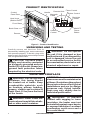
Heater Flame EmberBacklight
Power
Figure 2 - Product Identication
PRODUCT IDENTIFICATION
Heat Vents
(Behind Door)
ON/OFF
Power
Button
Log Set
Front Glass
Back Glass
Heater
Control
Flame Control
Ember Control
Handle
Remote
Control
Panel Door
Carefully remove unit from box. Prior to
permanently installing unit, test to make sure
unit operates properly. To do this, plug unit's
power supply cord into a conveniently located
120-volt grounded outlet.
CAUTION; The unit's power
supply cord must be connected
to a properly grounded and pro-
tected 120-volt outlet. Always use
ground fault protection where
required by the electrical code.
WARNING: Do not operate
the unit if it is damaged or has
malfunctioned. If you suspect the
unit is damaged, return the unit
to an authorized service facility
for examination, electrical or me-
chanical adjustment or repair.
WARNING: Due to high tem-
peratures, this heater should
be located out of trafc. Keep
combustible materials such
as furniture, pillows, bedding,
papers, clothes and curtains at
least 3 feet (0.9 m) from the front
of the heater.
WARNING: Never locate this
heater where it may fall into a bath-
tub or other water container.
NOTICE: Minimum and maximum
clearances must be maintained at
all times. Illustrations throughout
these instructions reect typical
installations and are for design
purposes only. Actual installa-
tions may vary slightly due to
individual preferences.
WARNING: To prevent
contact with sagging or loose
insulation, the heater must not
be installed against vapor barrier
or exposed insulation. Localized
overheating could occur and a
re could result.
Backlight
Control
Remote Hide
Magnetic
Catch

www.desatech.com
120927-54C 5
Figure 3 - Heater Locations
CAUTION: Do not expose the
heater to the elements (such as
rain, etc.)
CAUTION: Wear gloves
and safety glasses for protec-
tion during installation and
maintenance.
This electric replace can be installed in a
mantel, framed into a wall or installed into an
existing replace. If installing into a mantel,
follow mantel’s assembly instructions.
LOCATING FIREPLACE
Continued
Figure 3 illustrates a variety of ways the heater
may be located in a room. The heater may
be installed directly on the oor or raised on
a hearth.
INSTALLATION
WARNING - RISK OF FIRE!
The power cord must not be
pinched or against a sharp edge.
Secure cord to avoid tripping or
snagging to reduce the risk of re,
electric shock or personal injury.
Do not run cord under carpeting.
Do not cover cord with throw
rugs, runners or the like. Arrange
cord away from trafc areas and
where it will not be tripped over.
WARNING - RISK OF FIRE!
To prevent a possible re, do
not block air intake or exhaust
in any manner. Do not use on
soft surfaces where openings
may become blocked.
WARNING - RISK OF FIRE!
Do not blow or place insulation
against the rebox.
WARNING: If the information
in these instructions is not fol-
lowed exactly, a re or explosion
may result causing property dam-
age, personal injury or death.
Do not store or use gasoline or
other ammable vapors in the vi-
cinity of this or any other heater.
INSTALLING FIREPLACE
Select a suitable location that is not suscep-
tible to moisture and is a safe distance from
drapes, furniture and high trafc areas.
Note: Follow all national and local electrical
codes. This insert can be installed into either
an existing replace or as new construction/
renovation.
Installing in Mantel
1. Assemble mantel according to mantel
instructions.
2. Locate mantel near a wall (or corner
depending on mantel type) close to a
power source. You may have to alter base
boards to t mantel ush against wall.
3. Insert replace into front of mantel. Be
careful not to scratch nish on base. Fire-
place will t ush against front of mantel.
4. Plug replace into power source. Push
mantel with replace into nal location.
Existing Fireplace Installation
1. Thoroughly clean out existing replace
and hearth area.
2. Seal all drafts, vents or ash clean-outs
with berglass insulation. Seal ue. Once
sealed, close damper to stop debris from
falling onto unit.
3. If existing re box is susceptible to mois-
ture, cap top of chimney ue to prevent
inltration of water.
Corner Mantel
Installation
Wall Mantel
Installation
Framed
Into Wall
or Existing
Fireplace

www.desatech.com
120927-54C6
Note: It is strongly advised that you hire
a qualied professional to undertake this
step in order to prevent personal injury.
Once ue is capped, chimney is no longer
suitable for wood burning.
Note: Do not install this unit into a replace
that is prone to dampness; the area of instal-
lation must be dry.
4. Plan the power supply. If an existing
grounded outlet is near replace, power
cord can run along front of replace. If
cord is not long enough to reach outlet, a
grounded extension cord minimum AWG
No. 14 and rated to a minimum of 1875
watts, may be used. If you plan to cut or drill
a hole in existing replace for wiring, it is
best to hire a professional to do this step in
order to prevent personal injury. To reduce
the risk of re, do not run power cord under
rugs, carpets, etc. Arrange power supply
cord away from high trafc areas where it
may pose a tripping hazard.
WARNING: The solid fuel/gas
replace has been converted for
use with an electric insert and
cannot be used for original fuels
unless all original parts have
been replaced and the replace
has been reapproved by the au-
thority having jurisdiction.
New Construction or Renovation
1. Select a location away from combustible
materials such as curtains or drapes,
furniture, bedding, paper, etc.
2. Mark desired location on oor and store
unit in a safe, dry and dust free location.
3. Frame in an opening leaving at least 1/4"
(6 mm) around the edge of the unit (see
Framing). Any new wiring must be done in
compliance with local and national codes
and other applicable regulations in order
to reduce the risk of re, electric shock
or other injuries. Therefore, it strongly
recommended that you hire a professional
to complete any such work.
4. Plan you power supply route. See step 4
of Existing Fireplace Installation.
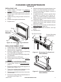
Framing
Figure 4, shows a typical framing of this heater
using combustible materials. All required
clearances to combustibles must be adhered
to. Header height is measured from the base
of the heater.
Tools and building supplies required for
installation:
• Saw • Square
• Pliers • Gloves
• Hammer • Level
• Phillips screwdriver • Surround
• Framing materials • Electric drill/bits
• Tape measure
• Wall-nishing materials
• Caulking material
INSTALLATION
Continued
Figure 4 - Framing Heater for New
Construction/Renovation
Length
Header
Height
Depth
0.75"-
0.50"
Model Depth Length
Header
Height
26" 9.75" 27" 26"
32" 10.5" 34" 32"
Note: The height that a
com busti ble ma ntel i s
tted above the heater is
dependent on the height
of the front selected. The
minimum height is 1" above
the front.

www.desatech.com
120927-54C 7
CAUTION: Provide adequate
clearances around the air open-
ings and adequate accessibility
clearances for servicing and
proper operations.
INSTALLATION
Continued
Heater Flame EmberBacklight
Power
Figure 5 - Controls For Electric Fireplace
Lighted Power Switch
Ember
Control
Heater
Control
Flame
Control
FINISHING
WARNING: Control panel door
on this heater cannot, in any way,
be covered as it may create a re
hazard.
Combustible Finishing Material: Materials
made of or surfaced with wood, compressed
paper, plant bers, plastics or any material
capable of igniting and burning, whether ame
proofed or not, plastered or unplastered (this
includes drywall).
Noncombustible Finishing Material : Ma-
terials which will not ignite and burn. Such
materials are those consisting entirely of
steel, iron, brick, tile, concrete, slate, glass
or plasters or combinations thereof or have a
re rating of zero.
FINISHING CHECKLIST
• Power supply service must be completed
prior to nishing to avoid reconstruction.
• Grills and air openings cannot be covered
in any circumstances.
Note: The heater is a zero clearance replace
and may be nished with combustible or non-
combustible nishing materials.
When using paint or lacquer to finish the
mantel, they must be heat resistant to prevent
discoloration.
Backlight
Control
Installing as Insert
Once the site has been prepared, your re-
place insert can be installed.
1. Make sure power switch is in the OFF
position.
2. Plug replace into a 15-amp/120 volt,
grounded outlet.
3. Push replace insert so trim is against n-
ished mantle or wall surface.
OPERATION
The controls (see Figure 5) are located behind
hinged control panel door. If using heater, con-
trol panel door will be hot during and immedi-
ately after operation. Open door by pressing
on right side. A spring magnet will push door
forward. Pull door down to open.
1. Plug in electric replace.
2. Turn on lighted power switch (see Figure 5).
3. Adjust Flame/Ember/Backlight/Heater
to desired settings using the control pad
on replace (Figure 5) or remote control
(Figure 6, page 8). Figure 7, page 8,
shows replace settings available. Default
settings are circled. Press control pad or
remote control buttons once and release
to adjust settings.
Note: When on, ember bed will lighten
and darken automatically to simulate real
embers.
The heater is pre-set to the following
temperatures:
High will shut off when room reaches ap-
proximately 86° F (30° C).
Medium will shut off when room reaches
approximately 79° F (26° C).
Low will shut off when room reaches ap-
proximately 72°F (22° C).
Note: Fan on heater will continue to run
for 5-7 seconds after heater has been
turned off.
4. When using remote control, aim remote
at sensor located in center of unit just
above log set. IMPORTANT: This remote
control must remain within 20 feet (6 m)
of replace to be effective.
5. When power switch is turned off, replace
settings go back to default (see Figure 7,
page 8).

www.desatech.com
120927-54C8
Figure 7 - Fireplace Settings (Default
Settings are Circled)
CLEANING AND MAINTENANCE
WARNING: Always discon-
nect power and allow the heater
to cool before performing any
cleaning, maintenance or reloca-
tion of this heater. Turn controls
to OFF and remove plug from
outlet or turn off circuit breaker
to heater.
To service electric replace it may be neces-
sary to remove it from the mantel or enclosure
in which it is installed. Let unit cool completely
before cleaning or servicing.
CLEANING FIREBOX
1. Open control panel door by pressing on
right side. A spring magnet will push door
forward. Pull door down to open.
2. Remove 2 screws holding front trim in
place. Pull gently to remove trim (see
Figure 8). There are magnets on the lower
portion of trim (see Figure 8)
3. With gloves and safety glasses in place,
remove 4 screws from glass retainer
brackets (see Figure 8).
4. Carefully remove front glass and brackets
(see Figure 9).
5. Using a brush vacuum attachment, gently
clean compartment.
6. After cleaning compartment, replace front
glass, brackets and trim.
Figure 9 - Removing Brackets and Front
Glass
Bracket
Front Glass
Figure 8 - Removing Trim
Magnets on
Back of Trim
Screws
Bracket
Trim
Control Panel
Door
OPERATION
Continued
HEATER Off Low Medium High
FLAME Off Low Medium High
EMBER Off Low Medium High
BACKLIGHT Off Low High
Figure 6 - Remote Control For Electric
Fireplace
Glass Bracket
Screws

www.desatech.com
120927-54C 9
Figure 10 - Removing Log and Ember
LED
Log
Ember LED
Strip with
Standoffs
REPLACING LOG
1. Follow steps 1 through 4 of Cleaning
Firebox, page 8.
2. Remove screws from each side of log that
secure log to sides and remove log (see
Figure 10).
3. Install new log using screws removed in
step 2.
4. Replace front glass and brackets.
5. Replace trim.
CLEANING AND MAINTENANCE
Continued
REPLACING EMBER STRIP
1. Follow steps 1 and 2 under Replacing Log.
2. Locate ember LED strip (see Figure 10).
Disconnect wire (right side).
3. Remove ember LED strip by squeezing
top of standoffs and discard.
4. Connect new ember LED strip using exist-
ing standoffs.
5. Reconnect wire to LED strip.
6. Follow steps 3 through 5 under Replac-
ing Log.
REPLACING HEATER/BLOWER
1. Follow steps 1 and 4 of Cleaning Firebox,
page 8.
2. Remove screws from around top panel of
rebox (see Figure 11).
3. There are several wires attached to the
top panel. Carefully lift top panel.
4. Disconnect heater/blower wires from main
circuit board.
5. Remove screws holding heater/blower to
top panel (see Figure 11).
6. Remove brackets from heater/blower (see
Figure 12). Save brackets and screws.
7. To remove heater from blower, remove 4
screws (2 per side).
8. If replacing blower, remove screws from
brackets on blower (see Figure 13,
page 10). Install brackets to new blower.
9. Replace blower or heater. Replace screws
removed in step 7.
10. Hold heater/blower with brackets in place
against top panel and replace screws
removed in step 5.
11. Reconnect wires to main circuit board (see
Wiring Diagram, page 14).
12. Replace glass with brackets, and top
panel.
13. Replace trim.
Figure 11 - Removing Top Panel and
Heater/Blower
Top Panel Screws
Screws Securing
Heater/Blower
Figure 12 - Removing Brackets from
Heater/Blower
Brackets
Screw

www.desatech.com
120927-54C10
REPLACING TRANSFORMER
1. Follow steps 1 through 3 under Replacing
Heater/Blower, page 9.
2. Disconnect transformer wires from control
board.
3. Remove screws and nuts from rebox
surround to remove transformer (see
Figure 14).
4. Remove and discard transformer.
5. Place new transformer against inside of
rebox surround and replace screws and
nuts removed in step 3.
6. Reconnect transformer wires to control
board (see Wiring Diagram, page 14).
7. Replace glass with brackets, and top
panel.
8. Replace trim
Figure 14 - Removing Transformer
Transformer
Screws
4. Gently push new control board onto
standoffs to install.
5. Reconnect wires to main control board
(see Wiring Diagram, page 14).
6. Replace glass with brackets, and top
panel.
7. Replace trim
REPLACING MAIN CONTROL BOARD
1. Follow steps 1 through 3 under Replacing
Heater/Blower, page 9.
2. Disconnect wires to main control board.
3. Squeeze top of standoffs to remove main
control board and discard.
Figure 15 - Control Board
Main Control
Board
Standoffs
Transformer
Figure 13 - Removing Heater from
Blower
Heater
Blower
CLEANING AND MAINTENANCE
Continued
REPLACING BACKLIGHT LED
STRIP
1. Follow steps 1 and 3 under Replacing
Heater/Blower, page 9.
2. Disconnect wires from main control
board.
3. Squeeze top of standoffs to remove back-
light LED strip and discard.
4. Place new backlight LED strip onto stand-
offs and push gently.
Figure 16 - Replacing Backlight LED
Strip
Backlight
LED Strip
Standoffs
Nuts

www.desatech.com
120927-54C 11
CLEANING AND MAINTENANCE
Continued
5. Connect wires to main control board (see
Wiring Diagram, page 14).
6. Replace glass with brackets, and top
panel.
REPLACING SETTINGS CONTROL
BOARD
1. Follow steps 1 through 3 under Replacing
Heater/Blower, page 9.
2. Disconnect wires from main control
board.
3. Remove screws from bracket to remove
settings control board.
4. Place new settings control board into posi-
tion making sure each control is aligned
with slot in panel. Install using screws
from step 3. DO NOT overtighten. This
will damage control board.
5. Reconnect wires to main control board
(see Wiring Diagram, page 14).
6. Replace glass with brackets, and top
panel.
7. Replace trim
LED Drum
Assembly
Screws
White Wire
Red
Wire
Figure 18 - Flame Generation LED Drum
Assembly
Motor
Figure 17 - Replacing Settings Control
Board
Screws
Settings
Control
Board
REPLACING FLAME GENERATION
LED
1. Follow steps 1 through 4 under Cleaning
Firebox, page 8
2. Remove screws from each side of log that
secure log to base and remove log (see
Figure 10, page 9).
3. Remove screws from sides and back of
bottom panel of rebox.
4. Gently lay unit on its back.
Clamps
5. There are several wires attached to bot-
tom panel. Carefully remove panel.
6. Disconnect wires from motor and LED
drum assembly.
7. Remove screws from bottom panel to
remove assembly.
8. If motor on assembly fails, loosen clamps
(see Figure 18). Remove screws from
motor. Hold universal joint while removing
motor and discard.
9. Install new motor. Slide motor shaft into
universal joint and tighten clamps.
10. Hold LED drum assembly in place on
bottom panel and replace screws.
11. Reattach wires to motor and LED drum.
Note: LED drum wires are polarity sensi-
tive and must be connected correctly.
White wire plugs onto left terminal and red
wire plugs onto right terminal. Motor wires
can be connected to either terminal.
12. Replace replace bottom panel. Set re-
place upright and replace screws.
13. Replace log, glass and brackets.
14. Reinstall replace and replace trim.

www.desatech.com
120927-54C12
CLEANING OR REPLACING BACK
SCREEN (GLASS)
1. The glass is cleaned in the factory during
assembly. During shipment, installation,
handling, etc. glass surface may collect
dust particles. These can be removed
by bufng lightly with a clean damp cloth
(water only). Glass should be completely
dried with a lint free cloth or paper towel.
2. In the event of glass breakage, vacuum all
remaining glass pieces with a shop vac. DO
NOT VACUUM WHILE PIECES ARE HOT.
Replace glass only with replacement part
specically for this heater. Never substitute
material. Only fully tempered soda lime
safety glass may be used on this heater.
3. To access glass to clean or replace, fol-
low steps 1 and 7 under Replacing Flame
Generation LED, page 11. Set aside bot-
tom panel.
4. Using gloves, gently remove glass panel
by sliding it toward you. There is a rubber
bumper on each corner of glass.
5. Clean glass as instructed in step 1 or
replace glass.
6. Using gloves, reinstall glass by gently
sliding, smooth side toward replace front,
into brackets on either side that hold glass
in place.
7. Replace log base.
8. Follow steps 11 and 14 under Replacing
Flame Generation LED, page 11.
TECHNICAL SERVICE
You may have further questions about instal-
lation, operation or troubleshooting. If so,
contact DESA Heating Products’ Technical
Service Department at 1-866-672-6040.
When calling please have your DESA model
and serial numbers of your heater ready.
You can also visit DESA Heating Products’
technical services web site at
www.desatech.com.
CLEANING AND MAINTENANCE
Continued
REPLACEMENT PARTS
Note: Use only original replacement parts.
This will protect your warranty coverage for
parts replaced under warranty.
PARTS UNDER WARRANTY
Contact authorized dealers of this product. If
they can’t supply original replacement part(s),
call DESA Heating Products’ Technical Ser-
vice Department at 1-866-672-6040.
When calling DESA Heating Products, have
ready
• your name
• your address
• DESA (distributor) model number and serial
number of your heater
• how heater was malfunctioning
• purchase date
Usually, we will ask you to return the part to
the factory.
PARTS NOT UNDER WARRANTY
Contact authorized dealers of this product. If
they can’t supply original replacement part(s),
call DESA Heating Products at 1-866-672-6040
for referral information.
When calling DESA Heating Products, have
ready
• DESA model number of your heater
• the replacement part number

www.desatech.com
120927-54C 13
TROUBLESHOOTING
WARNING: Turn off appliance and let cool before servicing. Only
a qualied service person should service and repair heater.
POSSIBLE CAUSE REMEDY
OBSERVED PROBLEM
1. Fireplace has overheated
and safety devise has cause
thermal switch to disconnect
or home circuit breaker has
opened
1. Loose wiring
2. Flame motor defective
1. Wiring is loose
1. Wiring is loose
1. Flame motor is defective
2. Flame generation contacts
dirty/obstructed
1. Low batteries
2. Not aiming control correctly
3. Defective remote control
and/or sensor
1. Fireplace is not plugged in
to an electrical outlet
2. Control failure
3. Breaker tripped
1. Thermal switch has been
tripped
2. Circuit breaker has been
tripped
3. Wiring is loose
4. Heater is defective
5. Thermostat cycled off
Fireplace turns off and will not
turn on
Flame is not moving
Flame is not visible
Log set and/or ember is not
glowing
Flame sputters/ashes
Remote control does not work
Fireplace will not come on when
switch is ipped to ON
Heater does not provide heat
when turned on
1. Reset switch by turning main
power switch off and waiting
5 minutes then turning it back
on or reset circuit breaker
1. Inspect wiring for loose
connections
2. Call a qualied service techni-
cian to replace ame motor
1. Disco nn ect fr om power
source and inspect wiring for
loose connections and repair
or replace if necessary
1. Disco nn ect fr om power
source and inspect wiring for
loose connections and repair
or replace if necessary
1. Call a qualied service techni-
cian to replace ame motor
2. Disconnect power. Follow
steps to replace ame gen-
eration LED. Clean contacts
with dry cloth.
1. Replace AAA batteries in
remote control
2. Aim control at sensor located
directly behind glass screen in
center of unit just above logs
3. Replace remote control and/
or sensor
1. Check plug
2. Call a qualied service tech-
nician to replace control
3. Reset breaker
1. Turn unit off and unplug unit
for 5 minutes. Plug back
in and turn unit on. If plug
cannot be reached, follow
directions for tripped circuit
breaker
2. Turn off circuit breaker that
supplies electricity to unit.
Wait 5 minutes then ip cir-
cuit breaker back on
3. Disco nn ect fr om power
source and inspect wiring for
loose connections and repair
or replace if necessary
4. Replace heater
5. Change to higher setting

www.desatech.com
120927-54C14
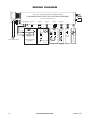
WIRING DIAGRAM
SETTINGS CONTROL BOARD
F801-0017-9000 (Rev. A)
1 V36 9
1 SCB 9
ON/OFF POWER
2
1
POWER CORD SETS
RED
WHITE
BLACK
BLACK
BLACK
BROWN BROWN
SCARLET
BLUE
BLK WHT RED
BRW BLU BRW LDA MTR LDS
LBS RCS
THM
SCT
120V/650W*2 120V/14W
24V/15W
120V/4W 24V/1W
24V/0.5W
SCARLET
BROWN
BROWN
BLUE
BLOWER
HEATER
HEATER
THERMOCOUPLE
HEATER/BLOWER
ASSEMBLY
LED FLAME
STRIP
WHITE
D
Syn. MOTOR
LED
V33
MODEL
MF500
REMOTE
SENSOR
THERMOSTAT
LED EMBER STRIP
LED BACKLIGHT
STRIP
TRANSFORMER
120V/60HZ
(12V+12V)/700MA
TF1TF
P/N F801-0015-9000 (Rev. A)
26" 32" 36" FIREPLACE MAIN CONTROL BOARD
PCB BOARD AND FUNCTION CONTROL ASSEMBLY

www.desatech.com
120927-54C 15
ACCESSORIES
Purchase these accessories from your local
dealer. If they can not supply these acces-
sories, call DESA Heating Products Sales
Department at 1-866-672-6040 for informa-
tion. Always refer to the DESA (distributor)
model number when referencing your heater.
You can also write to the address listed on
back this manual.
26" WALL MANTELS WITH BASE
AND TRIM (For 26" Models)
W26TU - 26" Wall Mantel, Unnished,
Traditional
W26TO - 26" Wall Mantel, Oak Stain,
Traditional
W26GO - 26" Wall Mantel, Oak Stain,
Georgian
26" CORNER MANTELS WITH BASE
AND TRIM (For 26" Models)
C26TU - 26" Corner Mantel, Unnished,
Traditional
C26TO - 26" Corner Mantel, Oak Stain,
Traditional
C26GO - 26" Corner Mantel, Oak Stain,
Georgian
32" MANTELS
W32TU - 32" Wall Mantel, Unnished,
Traditional
W32TO - 32" Wall Mantel, Oak Stain,
Traditional
C32TU - 32" Corner Mantel, Unnished,
Traditional
C32TO - 32" Corner Mantel, Oak Stain,
Traditional
W32CO - 32" Wall Mantel, Oak Stain, Classic
C32CO - 32" Corner Mantel, Oak Stain, Classic
W32DO - 32" Wall Mantel, Oak Stain, Dentil
W32GO - 32" Wall Mantel, Oak Stain,
Georgian
C32GO - 32" Corner Mantel, Oak Stain,
Georgian

www.desatech.com
120927-54C16
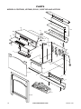
13
18
19
8
12
9
21
16
5
1
17
4
2
1 1
10
15
7
14
6
3
20
PARTS
MODELS CGEF26B, VEF26B, ES301, CGEF32D AND VEF32B

www.desatech.com
120927-54C 17
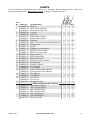
PARTS
This list contains replaceable parts used in your replace. When ordering parts, follow the
instructions listed under Replacement Parts on page 12 of this manual.
KEY
NO. PART NO. DESCRIPTION QTY.
1 120925-30 Blower • • 1
2 120927-06 Rear Glass (Screen) • 1
120928-06 Rear Glass (Screen) • 1
3 120927-05 Log Set • 1
120928-05 Log Set • 1
4 120927-07 Flame Effect Mirror • 1
120928-07 Flame Effect Mirror • 1
5 120927-08 Handles • • 2
6 120927-09 Main Control Board and Standoffs (5) • • 1
7 120927-10 Transformer • • 1
8 120927-11 Heater • • 1
9 120927-12 Settings Control Board • • 1
10 120927-13 LED Drum Assembly • 1
120928-13 LED Drum Assembly • 1
11 120927-14 Motor (Drum) • • 1
12 120927-15 LED Ember Strip • • 1
13 120927-20 Remote Control • • 1
14 120927-21 Remote Control Sensor • • 1
15 120927-22 Power Cord • • 1
16 120927-24 ON/OFF Switch • • 1
17 120927-03 Front Glass • 1
120928-03 Front Glass • 1
18 120927-02 Control Panel Door (Black) • 1
120928-02 Control Panel Door (Black) • 1
19 120927-25 Top (Black) • 1
120928-25 Top (Black) • 1
20 120927-01 Front Trim • 1
120928-04 Front Trim • 1
21 120926-32 Magnetic Catch • • 1
PARTS AVAILABLE NOT SHOWN
120927-17 Wire (Flame Effect) • 1
120928-17 Wire (Flame Effect) • 1
120927-18 Wire (Ember Bed) • 1
120928-18 Wire (Ember Bed) • 1
120927-19 Wire (Backlight) • 1
120928-19 Wire (Backlight) • 1
120927-23 Thermocouple • • 1
CGEF26B,
VEF26B, ES301
CGEF32D,
VEF32B,

www.desatech.com
120927-54C18
NOTES
_____________________________________________________
______________________________________________________
______________________________________________________
______________________________________________________
______________________________________________________
______________________________________________________
______________________________________________________
______________________________________________________
______________________________________________________
______________________________________________________
______________________________________________________
______________________________________________________
______________________________________________________
_____________________________________________________
______________________________________________________
______________________________________________________
______________________________________________________
______________________________________________________
______________________________________________________
______________________________________________________
______________________________________________________
______________________________________________________

www.desatech.com
120927-54C 19
NOTES
_____________________________________________________
______________________________________________________
______________________________________________________
______________________________________________________
______________________________________________________
______________________________________________________
______________________________________________________
______________________________________________________
______________________________________________________
______________________________________________________
______________________________________________________
______________________________________________________
______________________________________________________
_____________________________________________________
______________________________________________________
______________________________________________________
______________________________________________________
______________________________________________________
______________________________________________________
______________________________________________________
______________________________________________________
______________________________________________________
______________________________________________________
______________________________________________________
______________________________________________________
______________________________________________________
_____________________________________________________
______________________________________________________
______________________________________________________
______________________________________________________
______________________________________________________
______________________________________________________
______________________________________________________
______________________________________________________
______________________________________________________

120927-54
Rev. C
09/08
NOT A UPC
120926 26
DESA Heating, LLC
2701 Industrial Drive
Bowling Green, KY 42101
www.desatech.com
1-866-672-6040
WARRANTY
KEEP THIS WARRANTY
DESA HEATING, LLC LIMITED WARRANTIES
New Products
Standard Warranty: DESA Heating, LLC warrants this new product and any parts thereof to be free from
defects in material and workmanship for a period of one (1) year from the date of rst purchase from an
authorized dealer provided the product has been installed, maintained and operated in accordance with
DESA Heating, LLC’s warnings and instructions.
For products purchased for commercial, industrial or rental usage, this warranty is limited to 90 days from
the date of rst purchase.
Factory Reconditioned Products
Limited Warranty: DESA Heating, LLC warrants factory reconditioned products and any parts thereof
to be free from defects in material and workmanship for 30 days from the date of rst purchase from an
authorized dealer provided the product has been installed, maintained and operated in accordance with
DESA Heating, LLC’s warnings and instructions.
Terms Common to All Warranties
The following terms apply to all of the above warranties:
Always specify model number and serial number when contacting the manufacturer. To make a claim under
this warranty the bill of sale or other proof of purchase must be presented.
This warranty is extended only to the original retail purchaser when purchased from an authorized dealer,
and only when installed by a qualied installer in accordance with all local codes and instructions furnished
with this product.
This warranty covers the cost of part(s) required to restore this product to proper operating condition and
an allowance for labor when provided by a DESA Heating, LLC Authorized Service Center or a provider
approved by DESA Heating, LLC. Warranty parts must be obtained through authorized dealers of this prod-
uct and/or DESA Heating, LLC who will provide original factory replacement parts. Failure to use original
factory replacement parts voids this warranty.
Travel, handling, transportation, diagnostic, material, labor and incidental costs associated with warranty
repairs, unless expressly covered by this warranty, are not reimbursable under this warranty and are the
responsibility of the owner.
Excluded from this warranty are products or parts that fail or become damaged due to misuse, accidents,
improper installation, lack of proper maintenance, tampering, or alteration(s).
This is DESA Heating, LLC’s exclusive warranty, and to the full extent allowed by law; this express warranty
excludes any and all other warranties, express or implied, written or verbal and limits the duration of any
and all implied warranties, including warranties of merchantability and tness for a particular purpose to one
(1) year on new products and 30 days on factory reconditioned products from the date of rst purchase.
DESA Heating, LLC makes no other warranties regarding this product.
DESA Heating, LLC’s liability is limited to the purchase price of the product, and DESA Heating, LLC shall
not be liable for any other damages whatsoever under any circumstances including indirect, incidental, or
consequential damages.
Some states do not allow limitations on how long an implied warranty lasts or the exclusion or limitation of
incidental or consequential damages, so the above limitation or exclusion may not apply to you.
This warranty gives you specic legal rights, and you may also have other rights which vary from state to state.
For information about this warranty contact:
Model (
located on product or identication tag
) _____________________________
Serial No. (
located on product or identication tag
) __________________________
Date Purchased __________________________
Keep receipt for warranty verication.
-
 1
1
-
 2
2
-
 3
3
-
 4
4
-
 5
5
-
 6
6
-
 7
7
-
 8
8
-
 9
9
-
 10
10
-
 11
11
-
 12
12
-
 13
13
-
 14
14
-
 15
15
-
 16
16
-
 17
17
-
 18
18
-
 19
19
-
 20
20


Ask a question and I''ll find the answer in the document
Finding information in a document is now easier with AI
Related papers
-
Desa Tech CGEF23B Owner's manual
-
Desa VEF26B User manual
-
-
-
-
-
-
-
-
Other documents
-
CASAINC TS50 Installation guide
-
 Walker Edison Furniture Company HD8758 User manual
-
 EdenPURE PurATron Fireplace FP2011 User manual
-
Luxor LUXPWR Operating instructions
-
 Estate Design HYWN-23 User manual
-
 Northwest HW0200153 User manual
-
FMI C32TU Operating instructions
-
-
 Litton Lane 69268 Installation guide
-
 Litton Lane 53820 Installation guide


