KitchenAid GMC275PDB1 Installation guide
- Category
- Microwaves
- Type
- Installation guide

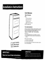
27" and 30" Electric
Built-in Microwave/
Oven Combination
Quick Reference
Table of Contents:
Pages
_1-_Product dimensions
[_ Cutout dimensions
[] Before you start
[] Electrical requirements
[_ _ Installation steps
If you need assistance:
Check your Useand Care Guide for a toll-free number to call or call
the dealer from whom you purchased this appliance. The dealer is
listed in the Yellow Pages of your phone directory under
"Appliances -- Household -- Major -- Service and Repair."
Call when you:
Have questions about built-in oven installation or operation.
[_ Need to obtain the name and number of an authorized service
company.
When you call, you will need:
The built-in oven model number.
[_ The built-in oven serial number.
Both numbers are listed on the model/serial rating plate, located on
the microwave oven frame.

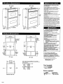
27" oven
25-3/8
recessed
41"
recessed
height
23" max.
recessed
depth
,26-314"
41-1/4"
cutout
height
1-1/2"
min.
bottom of
cutout to
top of
cab,net
door
"_ 27"min.
cabinetwidth
25-1/2"
,._----- cutout --
width
27" oven
cabinet ----
23-1/4"min.
q[---- cutout depth
23"recessed
oven depth
recessed
oven
Cabinet side view
J
42-7/16"
overall
height
1"top of cutout
tobottomof
upper cabinet
door
f
19-1/4"
bottom of
cutout to
floor
_3_
oven
"_front
41"
recessed
height
23" max.
recessed
depth
30" oven
28-3J8"
29-314"
42-7/16"
overall
height
J
T
41-I/4"
cutout
height
l,
1-1/2" rnin.
bottom of
cutout to
top of
cabinet
door
"9_'-- 30" mm.
cabinet
J
2S-1/2"
cutout ---_
width
30" oven
1"top
of cutout
to bottom
of upper
cabinet door
i
19-1/4"
bottom
of cutout
tofloor
_I_
Cabinet filler kits are available from your dealer.
Use a matching color kit if oven is smaller than your
cabinet opening.
27" oven filler height is7-13/16"
Black -- 4378950
White -- 4378951
Almond- 4378952
30" ovenfiller height is 4-13116"
Black -- 4378944
White -- 4378945
Almond- 4378946
Important: Observe all governing codes
and ordinances.
Proper installation isyour responsibility.
Have a qualified technician installthis oven.
Oven location should be away from strong draft
areas, such aswindows, doors and strong
heating vents.
Cabinet opening dimensions that are shown
must be used. Given dimensions provide
minimum clearance.
Recessedinstallation area must provide
complete enclosure aroundthe recessedportion
ofthe oven.
Electrical ground isrequired. See "Electrical
requirements."
Electrical supply junction box should be located
3 inchesmaximum below the support surface
when oven is installed in a wall cabinet. Cutout
for wiring should be in the right rear or left rear
corner. Forundercounter installation, it is
recommended that the junction box be located
in the adjacentright or left cabinet. If installing
junction box on rear wall behind oven,junction
box mustbe recessedand located in the upper
or lower right or left corner of cabinet.
Oven support surface MUST besolid, level and
flush with bottom of cabinetcutout.
Excessive Microwave Energy Exposure
Do Not attempt to operate the microwave
oven with the door open.
Do Not tamper with or defeat the safety
interlocks.
Do Not place objects between the microwave
oven front face and door.
Do Not allow soil or cleaner residue to
accumulate on sealing surface of the
microwave oven door.
Do Not operate the microwaveoven if
damaged.
Do Not operate the microwaveoven if:
-- door is bent.
-- hinges and latches are broken or loose.
-- door seals, sealing surfaces or glass are
broken.
The microwave oven door mustclose
properly to provide safe operation.
Havea qualified repair person adjust, repair
and check microwave oven for microwave
leakage after a repair is made.
Do Not use microwavefor commercial
purposes. The microwaveoven in this unit is
designed for household use only.
Failure tofollow these instructions could
result in exposure to excessive microwave
energy.
It is the customer's responsibility:
To contact a qualified electrical installer.
To assure that theelectrical installation is
adequate and in conformance with National
Electrical Code, ANSI/NFPA 70 -- latest edition*,
and all local codes and ordinances.
Copies of the standards listed may be obtained from:
* National Fire Protection Association
Batterymarch Park
Quincy, Massachusetts 02269
Tool needed:
Phillips screwdriver
Parts supplied:
Page 1

ElectricalShockHazard
Electricallygroundoven.
Connectgroundwith10-gauge-minimumsolid
copperwire.
Failuretofollow these instructionscould result
in death, fire or electrical shock.
.................. ,,,,,,,,
If codespermit and a separate grounding wire is
used, it isrecommended that a qualified electrician
determine that the grounding path and wire gauge
are in accordancewith local codes.
Do Not ground to a gaspipe.
Checkwith aqualified electricianif you are not
sure oven ispropedy grounded,
Do Not have a fuse in the neutral or grounding
circuit,
Oven must be connected to the proper electrical
voltage and frequency asspecified on the
model/serial rating plate. (The model/serial rating
plate is locatedon the oven door or on the oven
frame.)
[] CONNECTWITH COPPERWIRE ONLY,
[] Models rated from 7.3 to 9.6 kWat 240 volts
(5.5to 7.2 kW at 208 volts) requirea separate
40-ampere circuit, Models rated at 7.2 kWand
below at 240 volts (5.4 kW and below at 208
volts) require a separate 30-ampere circuit.
[] A time-delay fuse or circuit breaker is
recommended.
[]
[]
[]
[]
Connect directly tothe fused disconnect(or
circuit breaker box) through flexible, armored
or non-metallic sheathed, copper cable (with
grounding wire),
Flexible armored cablefrom applianceshould
be connected directly tojunction box.
Fuse both sidesof the line.
A U.L-listed conduitconnector must be
provided at the junction box.
[] Do Not cutthe conduit.
Wire sizesand connections must conform with
the rating ofthe applianceand to the
requirements ofthe National ElectricalCode,
ANSI/NFPA 70 --latest edition (% See Page 1)
and all localcodes and ordinances.
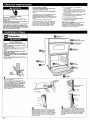
D Preparation
Excessive Weight Hazard
Usetwo or more peopleto moveand install
oven.
Failureto follow this instructioncan resultin
backor other injury,
Important: Useboth handsto remove oven
doors.
DONot usehandle or anyportion ofthe front
flame ortrim for lifting.
Beforemoving ovenacrossfloor,checkthat oven
ison shippingbaseor slideoven onto cardboard
or hardboard.
Do Not remove shippingfeet at the front lower
comersof oven.
DoNot _
remove
shipping feet,
" Turn power supply off. Move oven
closeto final position.
• Remove and discardshipping materials,
tape and protective film from the oven. Do
Not remove shipping base or shippingfeet
at the front lower cornersof oven. The
shippingfeet will protect the lower oven
trim until oven isinserted into cabinet.
• Remove and set aside racks and other parts
from inside oven.
D Remove
side trim
pieces.
D power
supply cable
shipping
foot
B Graspovenframe
to liftoven.
( )
D Checkoven and
microwave oven operation.
r_Use screws to attach
oven to cabinet.
_ eattach side
trim pisces.
Remove
trim screws.
Remove
oven door,
D Replace
oven door.
Insert small
end of pin
here.
Remove trim screw.
Ut,
Pulltop oftrim
down.
I
= Completely open lower oven door. Insert
small end of a door removal pin into eachdoor
hinge. Grasp door handle from the bottom and
gently close door as far as itwill shut. Liftslightly
and grasp bottom of door with other hand. Pull
door out at bottom to remove. Set door aside on
protected surface.
,. Remove trim screws attaching right and
left side trim to oven. Grasp the bottom end of
trim and pull away from oven. Slide top end of
trim downward to remove trim from oven. Take
care not to scratch other surfaces with ends of
trim. Set trim and screws aside on protected
surface.
Page 2

D Electricalconnection
Electrical Shock Hazard
Disconnectpower to the junction box before
making connection.
Electrically ground oven.
Connect ground with t0-gauge-minimum solid
copper wire.
Failure tofollow these instructionscould result
in death, fire or electrical shock.
This oven is manufactured with white (neutral)
power supply wire and a cabinet-connected bare
grounding wire twisted together.
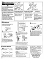
Feedoven cablethrough opening in
• the cabinet. Make electrical connection
following the stepsneededfor your installation.
1. Disconnectthe power supply.
2. Remove the junction box cover.
3. Connectoven cable to junction box through the
U.L.-listedconduit connector,
4. Connect the two blackwires together with
twist-on connectors,
5. Connect the two red wires together with
twist-on connectors,
6. Complete electrical connection according to
local codes and ordinances.
junction
box
r_h_.2e_
wires
W
wire
grounding oven
cable wires
factory crimped
Figure 1
cablefrom
power supply
cable from conduit
oven connector
If local codes PERMIT
connecting cabinet-grounding
conductor to neutral white
wire in junction box:
7. Connect the factory-crimped bare
and white oven cable wires to
the neutral (white) wire in
junction box. See Figure 1.
8. Replace junction box cover.
cablefrom
junction power supply
box
re; .w,i;:
k wires
bare grounding _ /
w,res _"_U ,L.-listedconduit
Figu re 2 cablefrom connector
oven
If local codes DO NOT PERMIT
connecting cabinet-grounding
conductor to neutral white
wire in junction box:
7. Separate the factory-crimped
bare and white oven cable wires.
8, Connect white oven cable wire to
neutral (white) wire in junction
box. See Figure 2,
9, Connect the bare grounding
oven cable wire to a grounded
wire in the junction box, See
Figure 2.
10. Replace junction box cover,
If connecting to a
four-wire electrical system:
7. Separate bare andwhite
oven cable wires,
8, Connect white oven cable wire to
neutral (white) wire in junction
box. See Figure 2.
9, Connect the bare grounding oven
cable wire to the green grounding
wire in junction box. Do Not
connectbare groundingwire to
neutral (white} wire in junction
box.See Figure2.
10. Replacejunction box cover.
Attachment
Carefully push against seal area of oven front
frame when pushing oven into cabinet.
Do Not push against outside edges.
• Lift oven into cabinet cutout using the
oven opening as an areato grip.
shL"ogn'
Push against seal area of front frame to push
oven intocabinet until shipping feet almost
contact cabinet. Use a Phillips screwdriver to
remove screws attaching shipping feet, Remove
and discard shipping feet.
Push oven completely into cabinet and center
oven in cabinet cutout,
14screws
• Important: Securelyfasten oven to cabinet
using the screws provided (two screws for a single
oven or four screws for a double oven). Insert the
screws through holes in mounting rails. Do Not
overtighten screws.
Pushtrim
into place.Replace
trim screw•
= Slide top end of each trim upward onto oven
side rails. Push each trim into place at bottom of
trim. Usescrews to attach each trim to oven. Take
care not to scratch other surfaces with ends of trim.
• Replace oven racks.
oven frame
door
hinge
Replacethe lower oven door by inserting
• ends of hinges into hinge slots in oven
frame. Push behind each hinge so that hinges are
pushed into oven frame as far asthey will go. Open
door and remove both door removal pins. Close
and open door to check that door closes and opens
completely. If door does not close or open
completely,you have not pushed hinges
completely intoframe. Repeatdoor removal step
and reinsert door into hingeslots again.
D Check operation
0 = Turn on power supply, The display
panel will light up briefly. "PF" should appear in
the temperature display.
Make sure the oven door isclosed and the "ON"
light isshown in the display area. After 2 minutes,
partially open oven door. You should feel heat from
the oven. Press the "CANCEL" pad.
If your oven does not heat or an"F" appears in
the display, contact your dealer or check the "If
you need service..." section of this Installation
Instructions.
IB'KliBOLIICLE'N1
n • Checkthe operation of your lower
1
oven. Pressthe "BROIL" pad, "BROIL" will
appear in the display. Press the "START" pad,
2. Checkthe operation ofthe
microwave oven.
• Fill a microwave-safe container with one cup of
water and place containerinside microwave oven.
Close doorfirmly.
• Set microwave oven cooktime to "2:00"
minutes,
• Pressthe "START/ENTER" pad.The interior
microwaveoven light shouldbeon and the
remaining cooking time should be displayed.
Page 3
• When display reads "1:00," open microwave
oven door, The microwave should stop cooking.
•Close door firmly. The interior microwave oven
light should turn off.
• Press the "START/ENTER" pad. Microwave oven
should begin cooking and the microwave oven
interior light should be on.
• Let microwave oven complete cooking time. A
tone will sound four times at end of cooking time
and microwave oven will shut off.
• Open microwave oven door and carefully remove
container. Water in container should be hot.
To get the most efficient use
from your new oven, read your
Use and Care Guide. Keep
Installation Instructions
and Guide close to oven
for easy reference.

If oven does not operate:
[_ Check that circuit breaker is not tripped or
house fuse blown.
[] See Use and Care Guide for troubleshooting list.
If you need assistance:
If you have questions about operating, cleaning or
maintaining your oven:
[] Referto Useand Care Guide.
Call the Consumer Assistance Center: Check
your Use and Care Guide for a toll-free
number to call or call the dealer from whom you
purchased this appliance. The dealer is listed in
the Yellow Pages of your phone directory under
"Appliances -- Household -- Major -- Service
and Repair."
If you need service:
Maintain the quality built into your built-in oven by
calling an authorized service company.
To obtain the name and number of an authorized
service company:
[] Contact the dealer from whom you purchased
your built-in oven; or
[] Look in the Yellow Pages of your telephone
directory under "Appliances -- Household --
Major -- Service and Repair" for an authorized
service company; or
[] Call the Consumer Assistance Center, The toll-
free number is listed in your Useand Care Guide.
When you call, you will need:
[] The built-in oven model number.
[] The built-in oven serial number.
Both numbers are listed on the model/serial rating
plate, located on the microwave oven frame.
Part No. 4450412 Rev,A
© 1996 Printed in U.S.A.
-
 1
1
-
 2
2
-
 3
3
-
 4
4
-
 5
5


KitchenAid GMC275PDB1 Installation guide
- Category
- Microwaves
- Type
- Installation guide
Ask a question and I''ll find the answer in the document
Finding information in a document is now easier with AI
Related papers
-
KitchenAid KEMC378KSS - ARCHITECT Series 27'' Microwave Combination Double Wall Oven Installation guide
-
Whirlpool RBD275PDT8 Installation guide
-
Whirlpool KEBC277KBL03 Installation guide
-
KitchenAid YKBMC140HS0 Installation guide
-
Whirlpool GBD307PDS4 Installation guide
-
-
Whirlpool KEMC308KWH02 Installation guide
-
KitchenAid YKEHV309PM01 Installation guide
-
KitchenAid W10045010 User manual
-
Whirlpool RBD245PDQ12 Installation guide
Other documents
-
Whirlpool Microwave Oven User manual
-
Whirlpool GSC308PRT01 Installation guide
-
Whirlpool RBS245PDT11 User manual
-
-
Magic Chef 9875XYB Installation guide
-
Whirlpool Electric Built-In Microwave/Oven User manual
-
Whirlpool RMC305PVS00 Installation guide
-
Frigidaire FGMC2766UFA Installation guide
-
Whirlpool Drop-In Ceramic Electric Range User manual
-
Whirlpool MMW7730DS Installation guide