Maytag MET3800TW2 Installation guide

Category
Electric laundry dryers
Type
Installation guide

This manual is also suitable for

27"(69CM)ELECTRICWASHER RYER
INSTALLATIONINSTRUCTIONS
INSTRUCTIONSD'INSTALLATION
# #
IAVEUSE/SECt USE E C I IQUE DE 27"(69CM)
Table ofContents/Table des matii_res
WASHER/DRYER SAFETY ............................. 1
iNSTALLATiON iNSTRUCTiONS ................... 2
Tools and Parts ............................................. 2
Alternate Parts ............................................... 2
Location Requirements ................................. 3
Drain System ................................................. 4
Electrical Requirements - U.S.A ................... 4
Electrical Requirements - Canada ................ 5
Electrical Connection - U.S.A. Only .............. 6
Venting Requirements ................................. 11
Remove Shipping Strap .............................. 12
Install Leveling Legs .................................... 12
Connect the Drain Hose .............................. 12
Connect the Inlet Hoses ............................. 13
Secure the Drain Hose ................................ 14
Plan Vent System ........................................ 14
Install Vent System ...................................... 15
Level Washer/Dryer ..................................... 15
Connect Vent .............................................. 15
Complete Installation .................................. 16
SC:CURIT_e DE LA LAVEUSE/SECHEUSE ... 17
INSTRUCTIONS D'INSTALLATION .............. 18
Outillage et pi_ces ....................................... 18
Autres pi_ces .............................................. 19
Exigences d'emplacement ........................ 19
Syst_me de vidange ................................... 20
Specifications _lectriques - Canada ........... 21
Exigences concernant I'_vacuation ............ 22
Enlever la sangle d'exp_dition .................... 23
Installation des pieds de nivellement .......... 24
Raccordement du tuyau de vidange .......... 24
Raccordement des tuyaux d'alimentation.. 24
Immobilisation du tuyau de vidange ........... 25
Planification du syst_me d'_vacuation ....... 26
Installation du syst_me d'_vacuation ......... 27
Nivellement de la laveuse/s_cheuse ........... 27
Raccordement du conduit d'_vacuation .... 28
Achever I'installation ................................... 28
WASHER RYER SAFETY
Your safety and the safety of others are very important.
We have provided many important safety messages in this manual and on your appliance. Always read and obey all safety
messages.
This is the safety alert symbol.
This symbol alerts you to potential hazards that can kilt or hurt you and others.
All safety messages will follow the safety alert symbol and either the word "DANGER" or "WARNING."
These words mean:
You can be killed or seriously injured if you don't immediately
follow instructions.
You can be killed or seriously injured if you don't follow
instructions.
All safety messages wilt tell you what the potential hazard is, tell you how to reduce the chance of injury, and tell you what can
happen if the instructions are not followed.
W10222378A
WARNING - "RiskofFire"
- Clothes dryer installation must be performed by a qualified installer.
- Install the clothes dryer according to the manufacturer's instructions and local codes.
- Do not instal( a clothes dryer with flexib(e plastic venting materials, if flexible metal
(foil type) duct is installed, it must be of a specific type identified by the appliance
manufacturer as suitable for use with clothes dryers. Flexible venting materials are
known to collapse, be easily crushed, and trap lint. These conditions will obstruct
clothes dryer airflow and increase the risk of fire.
- To reduce the risk of severe injury or death, follow all installation instructions.
- Save these instructions.
INSTALLATIONINSTRUCTIONS
Gather the required tools and parts before starting installation.Read
and follow the instructions provided with any tools listed here.
Parts needed for washer (not provided):
[] Inlet hoses [] Flat washers
To o_der:
[] Call the dealer from whom you purchased your washer/dryer.
[] Call the toll-free number listed on the cover of the Washer/
Dryer User instructions.
[] Visit the website listed on the cover of the Washer/Dryer
User instructions.
NOTE: Replace inlet hoses after 5 years of use to reduce the risk
of hose failure. Record hose installation or replacement dates for
future reference.
Tools needed:
[] #2 Phillips and flat-blade [] Level
screwdriver
[] Wood block (for leveling)
[] Adjustable wrench that
opens to 1" (25 mm) or 9_6" [] Ruler or measuring tape
open-end wrench (for [] Knife
adjusting washer/dryer feet) [] Vent clamps
[] 1¼.nut driver or socket
wrench (recommended) [] Pliers
[] Wire stripper (for U.S. [] Scissors
only, direct wire [] Tin snips (for new vent
installations) installations)
[] Caulking gun and
compound (for installing
new exhaust vent)
Parts supplied:
Remove parts package from the washer basket. Check that all
parts were included.
A B _C D
2
A. Front leveling feet with nuts (2) C. Drain hose
B. Shipping strap (not in parts bag. D Silver double-wire hose clamp
See "Remove Shipping Strap")
Parts needed:
Check local codes, electrical supply and venting, and read "Electrical
Requirements" and "Venting Requirements" before purchasing parts.
Mobile home installations require metal exhaust system hardware
available for purchase from the dealer from whom you purchased
your washer/dryer. For further information, please reference the
"Assistance or Service" section of the Washer/Dryer User instructions.
Your installation may require additional parts. For information on
ordering, please refer to the toll free phone numbers on the front
page of the Washer/Dryer User Instructions.
if You Have You Will Need to Buy
Laundry tub or Sump pump system (if not already
standpipe taller than available)
96" (2.4 m)
1" (25 mm) diameter 2" (51mm) diameter to 1" (25mm) diameter
standpipe standpipe adapter, Part Number 3363920
Overhead sewer Standard 20 gal. (76 L) 34" (864 mm) tall
drain tub or utility sink and sump pump
(available from local plumbing suppliers)
Floor drain Siphon break, Part Number 285320,
additional drain hose, Part Number
285702 and connector kit,
Part Number 285442
Drain hose too short Drain hose, Part Number 285664 and
connector kit, Part Number 285442
Lint clogged drain Drain protector, Part Number 367031
Water faucets 2 longer water fill hoses:
beyond reach of fill 6 ft (1.8 m) Part Number 76314,
hoses 10 ft (3.0 m) Part Number 350008
Washer/Dryer Dimensions
71%"
(1819 mm)
Explosion Hazard
Keep flammable materials and vapors, such as
gasoline, away from dryer.
FaiJure to do so can result in death, explosion, or fire.
You will need
[] A location that allows for proper exhaust installation. See
"Venting Requirements."
[]
[]
[]
[]
[]
[]
A separate 30-amp circuit.
If you are using a power supply cord, a grounded electrical
outlet located within 2 ft (610 mm) of either side of the washer/
dryer. See "Electrical Requirements."
A sturdy floor to support the washer/dryer weight (washer/
dryer, water, and load) of 500 Ibs (226.8 kg).
A level floor with a maximum slope of 1" (25 mm) under entire
washer/dryer. Clothes may not tumble properly and automatic
sensor cycles may not operate correctly if washer/dryer is not
level. Installing on carpet is not recommended.
A water heater set to deliver 120°F (49°C) water to the washer.
Hot and cold water faucets located within 4 ft (1.2 m) of the
hot and cold water fill valves, and water pressure of 5-100 psi
(34.5-689.6 kPa).
The washer/dryer must not be installed or stored in an area where
it will be exposed to water and/or weather.
Do not operate your washer in temperatures at or below 32°F
(0°C). Some water can remain in the washer and can cause
damage in low temperatures. See "Washer/Dryer Care" in the
Washer/Dryer User Instructions for winterizing information.
Do not operate your dryer at temperatures below 45°F (7°C). At
lower temperatures, the dryer might not shut off at the end of an
automatic cycle. This can result in longer drying times.
Check code requirements. Some codes limit, or do not permit,
installation of the washer/dryer in garages, closets, mobile homes,
or sleeping quarters. Contact your local building inspector.
Installation Clearances
The location must be large enough to allow the dryer door to open
fully.
27"
(686 mm)
*Most installations require a minimum 5" (127 mm) clearance
behind the dryer for the exhaust vent with elbow. See "Venting
Requirements."
Installation spacing for recessed area or closet installation
The following spacing dimensions are recommended for this
washer/dryer. This washer/dryer has been tested for spacing of 0"
(0 mm) clearance on the sides. Recommended spacing should be
considered for the following reasons:
[] Additional spacing should be considered for ease of
installation and servicing.
[]
[]
[]
Additional clearances might be required for wall, door,
and floor moldings.
Additional spacing on all sides of the washer/dryer is
recommended to reduce noise transfer.
For closet installation, with a door, minimum ventilation
openings in the top and bottom of the door are required.
Louvered doors with equivalent ventilation openings are
acceptable.
OoooO
I1 I
m
_i 27' il 1"
(25rnm) (686 inn]) (25mn])
A
I1 II
÷1 31"_Z;-_2,,I
1"*
_6"
(152inn])
48 il. 2 -
(310cn]2)
1
J 31_
-_(76 rnm)
|
24in.2- 2[ 3"
(155cm2)
(76n]m)
5"**
(25mn])(813n]rn)(127 mm)
B C
A. Recessed area
B. Side view - closet or confined area
C. Closet door with vents
*Required spacing
**Rear clearance may be 1" (25 mm) when house exhaust system
is lined up directly with dryer exhaust.
Mobile Home =Additional installation Requirements
This washer/dryer is suitable for mobile home installations.
The installation must conform to the Manufactured Home
Construction and Safety Standard, Title 24 CFR, Part 3280
(formerly the Federal Standard for Mobile Home Construction and
Safety, Title 24, HUD Part 280) or the Canadian Manufactured
Home Standard, CAN/CSA-Z240 MH.
MobiNe home installations require:
[] Metal exhaust system hardware, which is available for
purchase from your dealer.
[]
Special provisions must be made in mobile homes to
introduce outside air into the dryer. The opening (such as a
nearby window) should be at least twice as large as the dryer
exhaust opening.
The washer/dryer can be installed using the standpipe drain
system (floor or wall), the laundry tub drain system, or the floor
drain system. Select the drain hose installation method you need.
See "Alternate Parts."
Standpipe drain system =wall or floor {views A & B}
The standpipe drain requires a minimum diameter standpipe of
2" (51 mm). The minimum carry-away capacity can be no less than
17 gal. (64 L) per minute. A 2" (51 mm) diameter to 1" (25 mm)
diameter standpipe adapter kit is available. See "Alternate Parts."
The top of the standpipe must be at least 39" (991 mm) high and
no higher than 96" (2.4 m) from the bottom of the washer.
39 I_
(991 mm)
B
Laundry tub drain system {view C}
The laundry tub needs a minimum 20 gal. (76 L) capacity. The top
of the laundry tub must be at least 34" (864 mm) above the floor
and no higher than 96" (2.4 m) from the bottom of the washer.
Floor drain system {view D)
The floor drain system requires a siphon break that may be
purchased separately. See "Alternate Parts."
The siphon break must be a minimum of 28" (711 mm) from the
bottom of the washer. Additional hoses might be needed.
C D
It is your responsibility
[] Tocontact a qualified electrical installer.
[] To be sure that the electrical connection is adequate and in
conformance with the National Electrical Code, ANSl/NFPA
70-latest edition and all local codes and ordinances.
A copy of the above code standards can be obtained from:
National Fire Protection Association, One Batterymarch Park,
Quincy, MA 02269.
To supply the required 3 or 4 wire, single phase, 120/240 volt,
60 Hz., AC only electrical supply (or 3 or 4 wire, 120/208 volt
electrical supply, if specified on the serial/rating plate) on a
separate 30-amp circuit, fused on both sides of the line. A
time-delay fuse or circuit breaker is recommended. Connect
to an individual branch circuit. Do not have a fuse in the
neutral or grounding circuit.
[] Do not use an extension cord.
[] If codes permit and a separate ground wire is used, it is
recommended that a qualified electrician determine that the
ground path is adequate.
Electrical Connection
To properly install your washer/dryer, you must determine the type
of electrical connection you will be using and follow the
instructions provided for it here.
[] This dryer is manufactured ready to install with a 3-wire
electrical supply connection. The neutral ground wire is
permanently connected to the neutral conductor (white wire)
within the dryer. Ifthe dryer is installed with a 4-wire electrical
supply connection, the neutral ground wire must be removed
from the internal ground connector (green screw), and secured
under the neutral terminal (center or white wire) of the terminal
block. When the neutral ground wire is secured under the
neutral terminal (center or white wire) of the terminal block, the
dryer cabinet is isolated from the neutral conductor.
If local codes do not permit the connection of aneutral ground
wire to the neutral wire, see "Optional 3-wire connection" in
the "Electrical Connection - U.S.A. Only" section.
A 4-wire power supply connection must be used when the
appliance is installed in a location where grounding through
the neutral conductor is prohibited. Grounding through the
neutral is prohibited for (1) new branch-circuit installations,
(2) mobile homes, (3) recreational vehicles, and (4) areas
where local codes prohibit grounding through the neutral
conductors.
If using a power supply cord:
Use a UL listed power supply cord kit marked for use with clothes
dryers. The kit should contain:
[] A UL listed 30-amp power supply cord, rated 120/240 volt
minimum. The cord should be type SRD or SRDT and be at
least 4 ft (1.22 m) long. The wires that connect to the dryer
must end in ring terminals or spade terminals with upturned
ends.
[] A UL listed strain relief.
4
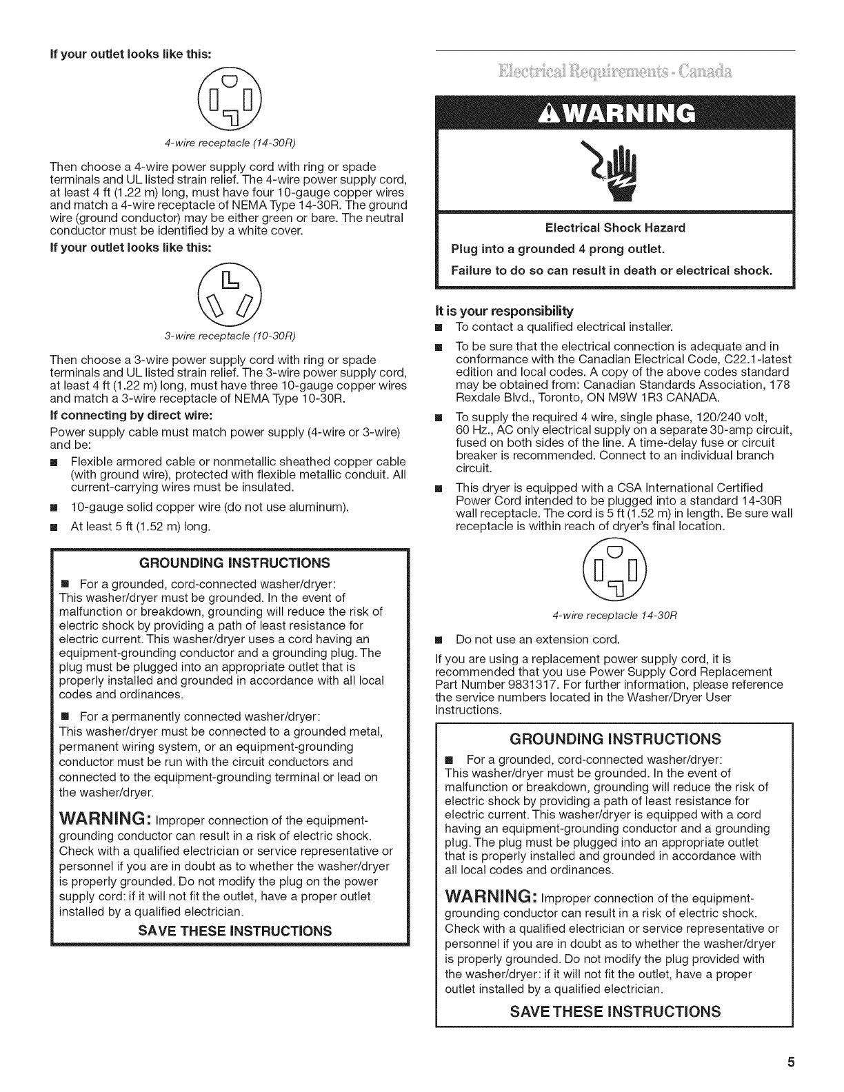
if your outlet looks like this:
4-wire receptacle (14-30R)
Then choose a 4-wire power supply cord with ring or spade
terminals and UL listed strain relief. The 4-wire power supply cord,
at least 4 ft (1.22 m) long, must have four 10-gauge copper wires
and match a 4-wire receptacle of NEMA Type 14-30R. The ground
wire (ground conductor) may be either green or bare. The neutral
conductor must be identified by a white cover.
If your outlet looks like this:
Electrical Shock Hazard
Plug into a grounded 4 prong outlet.
Failure to do so can result in death or electrical shock.
3-wire receptacle (10-30R)
Then choose a 3-wire power supply cord with ring or spade
terminals and UL listed strain relief. The 3-wire power supply cord,
at least 4 ft (1.22 m) long, must have three 10-gauge copper wires
and match a 3-wire receptacle of NEMA Type 10-30R.
If connecting by direct wire:
Power supply cable must match power supply (4-wire or 3-wire)
and be:
[] Flexible armored cable or nonmetallic sheathed copper cable
(with ground wire), protected with flexible metallic conduit. All
current-carrying wires must be insulated.
[] 10-gauge solid copper wire (do not use aluminum).
[] At least 5 ft (1.52 m) long.
GROUNDING INSTRUCTIONS
[] For a grounded, cord-connected washer/dryer:
This washer/dryer must be grounded. In the event of
malfunction or breakdown, grounding will reduce the risk of
electric shock by providing a path of least resistance for
electric current. This washer/dryer uses a cord having an
equipment-grounding conductor and a grounding plug. The
plug must be plugged into an appropriate outlet that is
properly installed and grounded in accordance with all local
codes and ordinances.
[] For a permanently connected washer/dryer:
This washer/dryer must be connected to a grounded metal,
permanent wiring system, or an equipment-grounding
conductor must be run with the circuit conductors and
connected to the equipment-grounding terminal or lead on
the washer/dryer.
WARNING: Improper connection of the equipment-
grounding conductor can result in a risk of electric shock.
Check with a qualified electrician or service representative or
personnel if you are in doubt as to whether the washer/dryer
is properly grounded. Do not modify the plug on the power
supply cord: if it wilt not fit the outlet, have a proper outlet
installed by a qualified electrician.
SAVE THESE INSTRUCTIONS
it is your responsibility
[] Tocontact a qualified electrical installer.
To be sure that the electrical connection is adequate and in
conformance with the Canadian Electrical Code, C22.1-1atest
edition and local codes. A copy of the above codes standard
may be obtained from: Canadian Standards Association, 178
Rexdale Blvd., Toronto, ON M9W 1R3 CANADA.
To supply the required 4 wire, single phase, 120/240 volt,
60 Hz., AC only electrical supply on a separate 30-amp circuit,
fused on both sides of the line. A time-delay fuse or circuit
breaker is recommended. Connect to an individual branch
circuit.
This dryer is equipped with a CSA International Certified
Power Cord intended to be plugged into a standard 14-30R
wall receptacle. The cord is 5 ft (1.52 m) in length. Be sure wall
receptacle is within reach of dryer's final location.
4-wire receptacle 14-30R
[] Do not use an extension cord.
If you are using a replacement power supply cord, it is
recommended that you use Power Supply Cord Replacement
Part Number 9831317. For further information, please reference
the service numbers located in the Washer/Dryer User
Instructions.
GROUNDING iNSTRUCTiONS
[] For a grounded, cord-connected washer/dryer:
This washer/dryer must be grounded. In the event of
malfunction or breakdown, grounding will reduce the risk of
electric shock by providing a path of least resistance for
electric current. This washer/dryer is equipped with a cord
having an equipment-grounding conductor and a grounding
plug. The plug must be plugged into an appropriate outlet
that is properly installed and grounded in accordance with
all local codes and ordinances.
WARNING" Improper connection of the equipment-
grounding conductor can result in a risk of electric shock.
Check with a qualified electrician or service representative or
personnel if you are in doubt as to whether the washer/dryer
is properly grounded. Do not modify the plug provided with
the washer/dryer: if it will not fit the outlet, have a proper
outlet installed by a qualified electrician.
SAVE THESE INSTRUCTIONS
Power Supply Cord
Fire Hazard
Use a new UL listed 30 amp power supply cord.
Use a UL listed strain relief.
Disconnect power before making electrical connections.
Connect neutral wire (white or center wire) to center
terminal (silver).
Ground wire (green or bare wire) must be connected to
green ground connector.
Connect remaining 2 supply wires to remaining
2 terminals (gold).
Securely tighten all electrical connections.
Failure to do so can result in death, fire, or
electrical shock.
Direct Wire
Fire Hazard
Use 10 gauge solid copper wire.
Use a UL listed strain relief.
Disconnect power before making electrical connections.
Connect neutral wire (white or center wire) to center
terminal (silver).
Ground wire (green or bare wire) must be connected to
green ground connector.
Connect remaining 2 supply wires to remaining
2 terminals (gold).
Securely tighten all electrical connections.
Failure to do so can result in death, fire, or
electrical shock.
1. Disconnect power.
2. Remove the hold-down screw and terminal block cover.
A
3. Install strain relief.
Style 1: Power supply cord strain relief
Remove the screws from a 3/4"(19 mm) UL listed strain relief
(UL marking on strain relief). Put the tabs of the two clamp
sections into the hole below the terminal block opening so
that one tab is pointing up and the other is pointing down, and
hold in place. Tighten strain relief screw enough to hold the
two clamp sections together.
E D
A. Center silver-colored terminal block screw
B. Hold-down screw
C. Terminal block cover
D. Neutral ground wire
E.External ground conductor screw
', .... "..................................D
A. Strain refief tab pointing up
B. Hole below terminal block opening
C. Clamp section
D. Strain refief tab pointing down
6
[]
[]
[]
4=
Put power supply cord through the strain relief. Be sure that
the wire insulation on the power supply cord is inside the
strain relief. The strain relief should have a tight fit with the
dryer cabinet and be in a horizontal position. Do not further
tighten strain relief screws at this point.
Style 2: Direct wire strain relief
Unscrew the removable conduit connector and any screws
from a 3/4"(19 mm) UL listed strain relief (UL marking on strain
relief). Put the threaded section of the strain relief through the
hole below the terminal block opening. Reaching inside the
terminal block opening, screw the removable conduit
connector onto the strain relief threads.
.......g
.......................... C
A. Removable conduit connector
B. Hole below terminalblock opening
C. Strainrelief threads
Put direct wire cable through the strain relief. The strain relief
should have a tight fit with the dryer cabinet and be in a
horizontal position. Tighten strain relief screw against the
direct wire cable.
Now complete installation following instructions for your type
of electrical connection:
4-wire (recommended)
3-wire (if 4-wire is not available)
Electrical Connection Options
If your home has: And you will be
connecting to:
Go to Section
4-wire receptacle A UL listed, 4-wire connection:
(NEMA Type 14-30R) 120/240 volt Power supply cord
(_ minimum,
30-amp, dryer
power supply
cord*
4-wire direct A fused 4-wire connection:
disconnect or Direct Wire
circuit breaker
box*
(127 ram)
3-wire receptacle A UL listed,
(NEMA type 10-30R) 120/240 volt
_j_ minimum,
30-amp, dryer
power supply
cord*
3-wire connection:
Power supply cord
3-wire direct A fused 3-wire connection:
disconnect or Direct Wire
circuit breaker
box*
(89 mm_
*If local codes do not permit the connection of a cabinet-ground
conductor to the neutral wire, go to "Optional 3-wire connection"
section.
4-wire connection: Power supply cord
IMPORTANT: A 4-wire connection is required for all mobile
homes and where local codes do not permit the use of 3-wire
connections.
C D E G
A. 4-wire receptacle (NEMA type 14-30R)
B. 4-prong plug
C. Ground prong
D. Neutral prong
E. Spade terminals with upturned ends
F. 3/4"(19 mm) UL fisted strain relief
G. Ring terminals
1.
2.
3.
Remove center silver-colored terminal block screw.
Remove neutral ground wire from external ground conductor
screw. Connect neutral ground wire and the neutral wire (white
or center wire) of power supply cord under center silver-
colored terminal block screw. Tighten screw.
A B
A. Neutral ground wire
B. Center silver-colored terminal block screw
C. External ground conductor screw
D. Neutral wire (white or center)
E. 3/4"(19 mm) UL listed strain relief
Connect ground wire (green or bare) of power supply cord
to external ground conductor screw. Tighten screw.
D
[
C
A
E
....F
A. External ground conductor screw
B. Ground wire (green or bare) of power supply cord
C. Neutral ground wire
D. Center silver-colored terminal block screw
E. Neutral wire (white or center)
E 3/4"(19 mm) UL listed strain relief
4. Connect the other wires to outer terminal block screws.
Tighten screws.
5. Tighten strain relief screws.
6. Insert tab of terminal block cover into slot of dryer rear panel.
Secure cover with hold-down screw.
7. You have completed your electrical connection. Now go to
"Venting Requirements."
4-wire connection: Direct Wire
iMPORTANT: A 4-wire connection is required for mobile homes
and where local codes do not permit the use of 3-wire
connections.
Direct wire cable must have 5 ft (1.52 m) of extra length so
washer/dryer can be moved if needed.
Strip 5" (127 mm) of outer covering from end of cable, leaving
bare ground wire at 5" (127 mm). Cut 11/2"(38 mm) from
3 remaining wires. Strip insulation back 1" (25 mm). Shape ends
of wires into a hook shape.
When connecting to the terminal block, place the hooked end of
the wire under the screw of the terminal block (hook facing right),
squeeze hooked end together, and tighten screw, as shown.
1.
2.
Remove center silver-colored terminal block screw.
Remove neutral ground wire from external ground conductor
screw. Connect neutral ground wire and place the hooked end
(hook facing right) of the neutral wire (white or center wire) of
direct wire cable under the center screw of the terminal block.
Squeeze hooked ends together. Tighten screw.
A B
S'
S_
C 1 ...........................................................E
A. Neutral ground wire
B. Center silver-colored terminal block screw
C. External ground conductor screw
D. Neutral wire (white or center wire)
E. 3/4,,(19 mm) UL fisted strain relief
8
3.
Connect ground wire (green or bare) of direct wire cable
to external ground conductor screw. Tighten screw.
E
F
4.
A. External ground conductor screw
B. Ground wire (green or bare) of power supply cord
C. Neutral ground wire
D. Center silver-colored terminal block screw
E. Neutral wire (white or center)
F. 3/4"(19 mm) UL listed strain refief
Place the hooked ends of the other power supply cable wires
under the outer terminal block screws (hooks facing right).
Squeeze hooked ends together. Tighten screws.
5. Tighten strain relief screw.
6. Insert tab of terminal block cover into slot of dryer rear panel.
Secure cover with hold-down screw.
7. You have completed your electrical connection. Now go to
"Venting Requirements."
r
3-wire connection: Power supply cord
Use where IocaJ codes permit connecting cabinet-ground
conductor to neutral wire.
C
D
E
G F
A. 3-wire receptacle (NEMA type 10-30R)
B. 3-wire plug
C. Neutral prong
D. Spade terminals with upturned ends
E. 3/4"(19 mm) UL listed strain relief
F. Ring terminals
G. Neutral (white or center wire)
1.
2.
Loosen or remove center silver-colored terminal block screw.
Connect neutral wire (white or center wire) of power supply
cord to the center silver-colored terminal screw of the terminal
block. Tighten screw.
A
A. External ground conductor screw
B. Neutral ground wire
C. Center silver-colored terminal block screw
D. Neutral wire (white or center wire)
E. 3/4"(19 mm) UL fisted strain relief
3. Connect the other wires to outer terminal block screws.
Tighten screws.
4. Tighten strain relief screws.
5. Insert tab of terminal block cover into slot of dryer rear panel.
Secure cover with hold-down screw.
6.
You have completed your electrical connection. Now go to
"Venting Requirements."
3-wire connection: Direct Wire
Use where local codes permit connecting cabinet-ground
conductor to neutral wire.
Direct wire cable must have 5 ft (1.52 m) of extra length so
washer/dryer can be moved if needed.
Strip 31/2'' (89 mm) of outer covering from end of cable. Strip
insulation back 1" (25 mm) if using 3-wire cable with ground wire,
cut bare wire even with outer covering. Shape ends of wires into a
hook shape.
kktkkttttkL >:
,_..........3A .....
{s9_m_
When connecting to the terminal block, place the hooked end of
the wire under the screw of the terminal block (hook facing right),
squeeze hooked end together, and tighten screw, as shown.
1=
2.
3.
Loosen or remove center silver-colored terminal block screw.
Place the hooked end of the neutral wire (white or center wire)
of direct wire cable under the center screw of terminal block
(hook facing right). Squeeze hooked end together. Tighten
screw.
C
B...............
A. External ground conductor screw
B. Neutral ground wire
C. Center silver-colored terminal block screw
D. Neutral wire (white or center wire)
E. 3/4"(19 mm) UL listed strain refief
Place the hooked ends of the other power supply cable wires
under the outer terminal block screws (hooks facing right).
Squeeze hooked ends together. Tighten screws.
!!
4. Tighten strain relief screw.
5. Insert tab of terminal block cover into slot of dryer rear panel.
Secure cover with hold-down screw.
6.
You have completed your electrical connection. Now go to
"Venting Requirements."
Use for direct wire or power supply cord where Ioca_ codes
do not permit connecting cabinet-ground conductor to
neutral wire.
1. Remove centersilver-colored terminal block screw.
2.
Remove neutral ground wire from external ground conductor
screw. Connect neutral ground wire and the neutral wire (white
or center wire) of power supply cord/cable under center,
silver-colored terminal block screw. Tighten screw.
E
3.
A. External ground conductor screw
B. Neutral ground wire
C. Neutral wire (white or center wire)
D. Grounding path determined by a quafified electrician
E. 3/4"(19 mm) UL listed strain relief
Connect the other wires to outer terminal block screws.
Tighten screws.
!!
4. Tighten strain relief screws.
5. Insert tab of terminal block cover into slot of dryer rear panel.
Secure cover with hold-down screw.
6.
Connect a separate copper ground wire from the external
ground conductor screw to an adequate ground.
10
Fire Hazard
Use a heavy metal vent.
Do not use a plastic vent.
Do not use a metal foil vent.
Failure to follow these instructions can result in death
or fire.
WARNING: To reduce the risk of fire, this washer/dryer
MUST BE EXHAUSTED OUTDOORS.
IMPORTANT: Observe all governing codes and ordinances.
The dryer exhaust must not be connected into any gas vent,
chimney, wall, ceiling, attic, crawlspace, or a concealed space
of a building.
if using an existing vent system
[] Clean lint from the entire length of the system and make sure
exhaust hood is not plugged with lint.
[] Replace any plastic or metal foil vent with rigid or flexible
heavy metal vent.
[] Review Vent system chart. Modify existing vent system if
necessary to achieve the best drying performance. Only
rigid or flexible metal vent shall be used for exhausting.
if this is a new vent system
Vent material
[] Use a heavy metal vent. Do not use plastic or metal foil vent.
[] 4" (102 ram) heavy metal exhaust vent and clamps must be
used. DURASAFE TM venting products are recommended.
4" (102mm) heavy metalexhaust vent
DURASAFE TM vent products can be purchased from your
dealer or by calling Whirlpool Parts and Accessories. For more
information, see the "Assistance or Service" section of the
Washer/Dryer User Instructions.
Rigid metal vent
[] For best drying performance, rigid metal vents are
recommended.
[] Rigid metal vent is recommended to avoid crushing and
kinking.
Flexible metaH vent
[] Flexible metal vents are acceptable only if accessible for
cleaning.
[]
[]
[]
[]
Flexible metal vent must be fully extended and supported
when the dryer is in its final location.
Remove excess flexible metal vent to avoid sagging and
kinking that may result in reduced airflow and poor
performance.
Do not install flexible metal vent in enclosed walls, ceilings,
or floors.
The total length of flexible metal vent should not exceed
73/4ft (2.4 m).
Elbows
45° elbows provide better airflow than 90° elbows.
Good Better
Clamps
[] Use clamps to seal all joints.
[] Exhaust vent must not be connected or secured with screws
or other fastening devices that extend into the interior of the
duct and catch lint. Do not use duct tape.
Clamp
Exhaust
Recommended hood styles are shown here.
(102 rnrn)
A. Louvered hood style
B.Box hood style
11
[]
[]
The angled hood style (shown here) is acceptable.
An exhaust hood should cap the vent to keep rodents and
insects from entering the home.
Exhaust hood must be at least 12" (305 mm) from the ground
or any object that may be in the path of the exhaust (such as
flowers, rocks or bushes, snow line, etc.).
[] Do not use an exhaust hood with a magnetic latch.
improper venting can cause moisture and lint to collect
indoors, which may result in:
[] Moisture damage to woodwork, furniture, paint, wallpaper,
carpets, etc.
[] Housecleaning problems and health problems.
Excessive Weight Hazard
Use two or more people to move and install
washer/dryer.
Failure to do so can result in back or other injury.
To avoid floor damage, set washer/dryer onto cardboard before
moving across floor. Move washer/dryer close to its final location.
1. Do not cut yellow strap. Pull yellow strap firmly, until
completely removed from washer/dryer. There should be
2 cotter pins on the end of the shipping strap. Remove the
hang tag and pin from the vent pipe.
2. Tilt the washer/dryer forward. Move each of the 2 rear legs in
an up-down motion to check the self-adjusting leveling legs
for free movement. This is required for proper leveling. Gently
lower the washer/dryer to the floor.
3. Cut the shipping strap about 16" (406 mm) from the plug end.
Look for the words "CUT HERE." Discard end with cotter pins.
You will use the remaining piece of shipping strap to secure
the drain hose.
install the front leveling feet
1. Prop up the front of the washer/dryer about 4" (102 mm) with
a wood block or similar object. The block needs to support
the weight of the washer/dryer.
2. Screw the Iocknut onto each foot to within 1" (25 mm) of the
base.
(25 mm)
f
.......... j
3. Screw the feet into the correct holes at the front corner of the
washer/dryer until the nuts touch the washer.
NOTE: Do not tighten the nuts until the washer/dryer is level.
4. Tilt the washer/dryer back and remove the wood block. Gently
lower the washer/dryer to the floor.
Proper connection of the drain hose protects your floors from
damage due to water leakage. To keep the drain hose from
coming off or leaking, it must be installed according to the
following instructions:
iMPORTANT: To ensure proper installation, this procedure must
be followed exactly.
1. Check the drain hose to see whether it is the proper length.
2. Wet the inside of the straight end of the drain hose with tap
water.
iMPORTANT: Do not use any lubricant other than water.
3. Squeeze ears of the silver double-wire clamp with pliers to
open. Place clamp over the straight end of the drain hose
1¼.(6.4 mm) from the end.
4. Open clamp. Twist hose back and forth while pushing onto
drain connector on the side of the washer/dryer. Continue until
hose contacts the ribbed stops on the cabinet.
5. Place clamp over the area marked "CLAMR" Release clamp.
12
For laundry tub or standpipe drain systems
1. Make sure drain hose form is in correct position.
.........................................................A
A.Drain hoseform
2. Put hooked end of drain hose into laundry tub or standpipe.
Rotate hook to eliminate kinks.
To keep drain water from going back into the washer:
[] Do not force excess drain hose into standpipe. Hose should
be secure but loose enough to provide a gap for air.
[] Do not lay excess hose on the bottom of the laundry tub.
For use with floor drain
Do not install the drain hose form onto the corrugated drain hose.
You may need additional parts. See Floor drain under "Tools and
Parts."
1= Insert a new flat washer into each end of the inlet hoses
(not provided). Firmly seat the washers in the couplings.
A B
A.Coupling
B.Washer
Connect the inlet hoses to the water faucets
Make sure the washer basket is empty.
1. Attach hose to the hot water faucet. Screw on coupling by
hand until it is seated on the washer.
2. Attach hose to the cold water faucet. Screw on coupling by
hand until it is seated on the washer.
3. Using pliers, tighten the couplings with an additional two-
thirds turn.
NOTE: Do not overtighten or use tape or sealants on the valve.
Damage to the valves can result.
Clear the water lines
[] Run water through both faucets and inlet hoses, into a
laundry tub, drainpipe, or bucket to get rid of particles in the
water lines that might clog the inlet valve screens.
[] Check the temperature of the water to make sure that the hot
water hose is connected to the hot water faucet and that the
cold water hose is connected to the cold water faucet.
Connect the inlet hoses to the washer
1. Attach the hot water hose to the bottom inlet valve. Attaching
the hot water hose first makes it easier to tighten connection
with pliers.
2. Screw on coupling by hand until it is seated on the washer.
3. Using pliers, tighten the couplings with an additional two-
thirds turn.
NOTE: Do not overtighten or use tape or sealants on the valve.
Damage to the valves can result.
in the U.S.A.
, -::
A. Cold water inlet valve (top)
B. Hot water inlet valve (bottom)
In Canada
A.Cold water inlet valve(top)
B.Hot water inlet valve(bottom)
4. Attach the cold water hose to the top inlet valve.
5. Screw on coupling by hand until it is seated on the washer.
6. Using pliers, tighten the couplings with an additional two-
thirds turn.
NOTE: Do not overtighten or use tape or sealants on the valve.
Damage to the valves can result.
(f you are working in a closet or recessed area
Move the washer/dryer into its final location and remove
cardboard from under washer/dryer. Remove the access panel by
removing 3 Phillips-head screws and one bumper, located at the
top of the access panel. Set panel, screws, and bumper aside.
Complete hookup of water hoses. Replace access panel upon
completion of washer/dryer installation.
Check for leaks
[] Turn on the water faucets and check for leaks. A small amount
of water might enter the washer. You will drain this water later.
NOTE: Replace inlet hoses after 5 years of use to reduce the risk
of hose failure. Record hose installation or replacement dates for
future reference.
[] If you connect only one water hose, you must cap off the
remaining water inlet port.
[] Periodically inspect and replace hoses if bulges, kinks, cuts,
wear, or leaks are found.
[] The apparatus must be connected to the water faucets using
the new hoses. Do not use old hoses.
13
1. Move the washer/dryer to its final location and remove any
cardboard used to move the washer/dryer.
2. Locate the remaining piece of shipping strap. See "Remove
Shipping Strap."
3=
Shipping strap
Wrap the drain hose to the laundry tub leg or standpipe with
the shipping strap (A or B below). Push fastener into the
nearest hole in the shipping strap (see illustration above).
A B C
If the water faucets and the drain standpipe are recessed, put
the hooked end of the drain hose in the standpipe. Tightly
wrap the shipping strap around the water inlet hoses and the
drain hose (C above). Push fastener into the nearest hole in
the shipping strap (see illustration above).
Choose your exhaust installation type
Recommended exhaust installations
Typical installations vent the dryer from the rear of the washer/
dryer. Other installations are possible.
.......................O
A ................................................
C ............... _ H
A. Dryer
B. Rigid metal or flexible metal vent
C. Clamps
D. Wall
E.Elbow
F. Clamps
G. Elbow
H. Exhaust hood
Optional exhaust installations
This washer/dryer can be converted to exhaust out the right
or left side. To convert the washer/dryer, use Side Exhaust Kit
Part Number 279823. If your washer/dryer was previously
exhausted from the right or left side, it can be converted to rear
exhaust by using standard offset connections. To cover the hole
in the side, one of the following plugs can be added:
692790 (white)
3977784 (biscuit)
Follow the instructions in the kit to install. Kits are available from
the dealer from whom you purchased your washer/dryer.
A B C
A.Standard rear offset exhaust installation
B.Rear exhaust foroffset close clearanceconnection
C.Left or right side exhaust instaflation
Alternate installations for close clearances
Venting systems come in many varieties. Select the type best for
your installation. Three close-clearance installations are shown.
Refer to the manufacturer's instructions provided with the vent
system.
=ii:ii
" ,,
A B C
A. Loop system with standard elbows
B. Loop system with one offset and one standard elbow
C. Vent system with one periscope (2" [51 mm] clearance)
NOTE: The following kits for close clearance alternate installations
are available for purchase. Please reference the "Assistance or
Service" section of the Washer/Dryer User Instructions.
[] Over-the-Top Installation:
Part Number 4396028
Periscope Installation (For use with dryer vent to wall vent
mismatch):
Part Number 4396037 - 0" (0 mm) to 18" (457 mm) mismatch
Part Number 4396011 - 18" (457 mm) to 29" (737 mm)
mismatch
Part Number 4396014 - 29" (737 mm) to 50" (1.27 m)
mismatch
14
Special provisions for mobile home insta(lations
The exhaust vent must be securely fastened to a noncombustible
portion of the mobile home structure and must not terminate
beneath the mobile home. Terminate the exhaust vent outside.
1. Install exhaust hood. Use caulking compound to seal exterior
wall opening around exhaust hood.
2. Connect vent to exhaust hood. Vent must fit inside exhaust
hood. Secure vent to exhaust hood with 4" (102 mm) clamp.
3. Run vent to dryer location. Use the straightest path possible.
See "Determine vent path" in "Plan Vent System." Avoid 90°
turns. Use clamps to seal all joints. Do not use duct tape,
screws, or other fastening devices that extend into the interior
of the vent to secure the vent, because they can catch lint.
Determine vent path
[] Select the route that will provide the straightest and most
direct path outdoors.
[] Plan the installation to use the fewest number of elbows and
turns.
[] When using elbows or making turns, allow as much room as
possible.
[] Bend vent gradually to avoid kinking.
[] Use the fewest 90° turns possible.
Determine vent length and elbows needed for best drying
performance
[] Use the Vent system chart below to determine type of vent
material and hood combinations acceptable to use.
NOTE: Do not use vent runs longer than those specified inthe
Vent system chart. Exhaust systems longer than those
specified will:
[] Shorten the life of the dryer.
[] Reduce performance, resulting in longer drying times and
increased energy usage.
The Vent system chart provides venting requirements that will help
to achieve the best drying performance.
Vent system chart
NOTE: Side exhaust installations add a 90° turn inside the dryer.
To determine maximum exhaust length, add one 90° turn to the
chart.
Number of Type of Vent Box or Ang(ed
90° turns Louvered hoods
or elbows hoods
0 Rigid metal 37 ft (11.3 m) 35 ft (10.7 m)
1 Rigid metal 32 ft (9.7 m) 27 ft (8.2 m)
2 Rigid metal 24 ft (7.3 m) 19 ft (5.8 m)
Properly leveling your washer/dryer avoids excessive noise and
vibration.
1. Check the levelness of the washer/dryer by placing a level
on the top edge of the washer, first side to side, then front
to back.
2. If the washer/dryer is not level, prop up the front with the
wood block and adjust the feet up or down as necessary.
Remove wood block.
3=
4=
Tilt the washer/dryer forward until the rear of the washer/dryer
is at least 4" (102 mm) off the floor. You may hear the self-
adjusting rear feet click into place. Lower the washer/dryer to
the floor. Check the levelness of the washer/dryer with a level
as shown above.
If washer/dryer will not level, recheck rear leveling legs for free
movement as described in the "Install Leveling Legs" section.
Repeat until the washer/dryer is level.
NOTE: It may be necessary to level the washer/dryer again
after it is moved into its final location.
After the washer/dryer is in its final location and is level, use an
adjustable or open-end wrench to turn the nuts on the front
feet tightly against the washer cabinet.
If the nuts are not tight against the washer cabinet, the
washer/dryer may vibrate.
1. Using a 4" (102 mm) clamp, connect vent to exhaust outlet
in washer/dryer. If connecting to existing vent, make sure the
vent is clean. The vent must fit over the exhaust outlet and
inside the exhaust hood. Make sure the vent is secured to
exhaust hood with a 4" (102 mm) clamp.
2. Move washer/dryer into its final location. Do not crush or kink
vent. Make sure washer/dryer is level.
15
1=
2.
3.
4.
5.
6.
Check that all parts are now installed. If there is an extra part,
go back through the steps to see which step was skipped.
Check that you have all of your tools.
Dispose of/recycle all packaging materials. Keep the plastic
foam for use if the washer/dryer should be transported.
Check the washer/dryer's final location. Be sure the vent is not
crushed or kinked.
Check that the washer/dryer is level and front leveling feet are
tight. See "Level Washer/Dryer."
in the U.S.A.
[] For power supply cord installation, plug into a grounded
outlet. For direct wire installation, turn on power.
In Canada
Electrical Shock Hazard
Plug into a grounded 4 prong outlet.
Failure to do so can result in death or electrical shock.
[] Plug into a grounded 4 prong outlet. Turn on power.
7. Check that the water faucets are on.
8. Check for leaks around faucets and inlet hoses.
9o Remove the blue protective film on the console and any tape
remaining on the washer/dryer.
10. Read the Washer/Dryer User Instructions.
11. Wipe the dryer drum interior thoroughly with a damp cloth
to remove any dust.
12. To test the washer, measure 1/2the normal recommended
amount of detergent and pour it into the washer. Close the lid.
Select HEAVY DUTY and pull out the Cycle Control knob.
Allow the washer to complete one whole cycle.
13. To test the dryer, set the dryer on a full heat cycle (not an air
cycle) for 20 minutes and start the dryer.
If the dryer will not start, check the following:
[] Controls are set in a running or "On" position.
[] Start button has been firmly pushed.
[] Washer/dryer is plugged into a grounded outlet.
[] Electrical supply is connected.
[] Household fuses are intact and tight, or circuit breakers
have not tripped.
[] Dryer door is closed.
14.
When the dryer has been running for 5 minutes, open the
dryer door and feel for heat.
if you do not feel heat, turn off the dryer and check the
following:
There may be 2 household fuses or circuit breakers for the
dryer. Check that both fuses are intact and tight, or that
both circuit breakers have not tripped. If there is still no
heat, contact a qualified technician.
NOTE: You may notice an odor when dryer is first heated.
This odor is common when the heating element is first used.
The odor will go away.
16
W10222378A
2008.
All rights reserved.
Tous droits reserv6s.
Benton Harbor, Michigan 49022
TM DURASAFE is a trademark of Whirlpool, U.S.A., Whirlpool Canada LP licensee in Canada
TM DURASAFE est une marque de commerce de Whirlpool, U.S.A., Emploi licencie par Whirlpool Canada LP au Canada
10/08
Printed in U.S.A.
Imprime aux E.-U.
  • Page 1 1
  • Page 2 2
  • Page 3 3
  • Page 4 4
  • Page 5 5
  • Page 6 6
  • Page 7 7
  • Page 8 8
  • Page 9 9
  • Page 10 10
  • Page 11 11
  • Page 12 12
  • Page 13 13
  • Page 14 14
  • Page 15 15
  • Page 16 16
  • Page 17 17
  • Page 18 18
  • Page 19 19
  • Page 20 20
  • Page 21 21
  • Page 22 22
  • Page 23 23
  • Page 24 24
  • Page 25 25
  • Page 26 26
  • Page 27 27
  • Page 28 28
  • Page 29 29

Maytag MET3800TW2 Installation guide

Category
Electric laundry dryers
Type
Installation guide
This manual is also suitable for

Ask a question and I''ll find the answer in the document

Finding information in a document is now easier with AI

in other languages