3
SAFETY INSTRUCTIONS
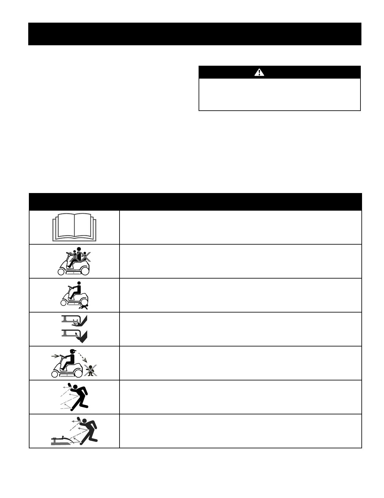
• Check overhead clearances carefully before driving under low hanging tree
branches, wires, door openings etc., where the operator may be struck or
pulled from the machine, which could result in serious injury.
• Disengage all attachment clutches and depress the brake pedal completely
before attempting to start engine.
• Your machine is designed to cut normal residential grass of a height no more
than 12”. Do not attempt to mow through unusually tall, dry grass (e.g.,
pasture) or piles of dry leaves. Dry grass or leaves may contact the engine
exhaust and/or build up on the mower deck presenting a potential fire
hazard.
• Use only accessories and attachments approved for this machine by the
machine manufacturer. Read, understand and follow all instructions
provided with the approved accessory or attachment. For a list of approved
accessories and attachments, call 1-888-331-4569.
• Data indicates that operators, age 60 years and above, are involved in a
large percentage of riding mower-related injuries. These operators should
evaluate their ability to operate the riding mower safely enough to protect
themselves and others from serious injury.
• If situations occur which are not covered in this manual, use care and good
judgment.
SLOPE OPERATION
Slopes are a major factor related to loss of control and tip-over accidents which can result in severe
injury or death. All slopes require extra caution. If you cannot back up the slope or if you feel uneasy on
it, do not mow it.
For your safety, use the Slope Guide included as part of this manual to measure slopes before operating
this machine on a sloped or hilly area. If the slope is greater than 12 degrees as shown on the Slope
Guide, do not operate this machine on that area or serious injury could result.
Do:
• Mow up and down slopes, not across. Exercise extreme caution when
changing direction on slopes.
• Watch for holes, ruts, bumps, rocks, or other hidden objects. Uneven terrain
could overturn the machine. Tall grass can hide obstacles.
• Use slow speed. Choose a low enough speed setting so that you will not have
to stop or shift while on the slope. Tires may lose traction on slopes even
though the brakes are functioning properly. Always keep machine in gear
when going down slopes to take advantage of engine braking action.
• Follow the manufacturer’s recommendations for wheel weights or
counterweights to improve stability.
• Use extra care with grass catchers or other attachments. These can change
the stability of the machine.
• Keep all movement on the slopes slow and gradual. Do not make sudden
changes in speed or direction. Rapid engagement or braking could cause
the front of the machine to lift and rapidly flip over backwards which could
cause serious injury.
• Avoid starting or stopping on a slope. If tires lose traction, disengage the
blade(s) and proceed slowly straight down the slope.
Do Not:
• Do not turn on slopes unless necessary; then, turn slowly and gradually
downhill, if possible.
• Do not mow near drop-offs, ditches or embankments. The mower could
suddenly turn over if a wheel is over the edge of a cliff, ditch, or if an edge
caves in.
• Do not try to stabilize the machine by putting your foot on the ground.
• Do not use a grass catcher on steep slopes.
• Do not mow on wet grass. Reduced traction could cause sliding.
• Do not attempt to coast downhill. Over-speeding may cause the operator to
lose control of the machine resulting in serious injury or death.
• Do not tow heavy pull behind attachments (e.g. loaded dump cart, lawn
roller, etc.) on slopes greater than 5 degrees. When going down hill, the
extra weight tends to push the tractor and may cause you to loose control
(e.g. tractor may speed up, braking and steering ability are reduced,
attachment may jack-knife and cause tractor to overturn).
CHILDREN
Tragic accidents can occur if the operator is not alert to the presence of children. Children are often
attracted to the machine and the mowing activity. They do not understand the dangers. Never assume
that children will remain where you last saw them.
• Keep children out of the mowing area and in watchful care of a responsible
adult other than the operator.
• Be alert and turn machine off if a child enters the area.
• Before and while backing, look behind and down for small children.
• Never carry children, even with the blade(s) shut off. They may fall off and be
seriously injured or interfere with safe machine operation.
• Use extreme care when approaching blind corners, doorways, shrubs, trees
or other objects that may block your vision of a child who may run into the
machine.
• To avoid back-over accidents, always disengage the cutting blade(s) before
shifting into Reverse. If equipped, the “Reverse Caution Mode” (blades
operate while machine rides in reverse) should not be used when children or
others are around.
• Keep children away from hot or running engines. They can suffer burns from
a hot muffler.
• Remove key when machine is unattended to prevent unauthorized
operation.
Never allow children under 14 years of age to operate this machine. Children 14 and over should read
and understand the instructions and safe operation practices in this manual and on the machine and
should be trained and supervised by an adult.
TOWING
• Tow only with a machine that has a hitch designed for towing. Do not attach
towed equipment except at the hitch point.
• Follow the manufacturers recommendation for weight limits for towed
equipment and towing on slopes.
• Never allow children or others in or on towed equipment.
• On slopes, the weight of the towed equipment may cause loss of traction and
loss of control.