18
# 8 5149 USB PC-Kabel
# 8 5213 MPX-M6 (male)
# 8 5190 Antiash 70
# 8 5214 MPX-M6 (female)
ROXXY Motoren
Roxxy LiPo
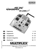
COCKPIT SX 7 / SX 9PROFI TX 9 / 12 / 16
Royal SX 9 / 16
10.0 Zubehör
D
GB
Operating Instructions
SMART Control
45A · 70A · 100 A
O
3
Contents
Congratulations on your purchase of the new ROXXY Smart Control brushless speed controller. We are delighted
that you have chosen a product from the MULTIPLEX range. The ROXXY Smart Control speed controller provides
all the usual basic functions, but it also offers the facility to generate a great deal of data - including voltage,
current, temperature, rotational speed and residual capacity - and pass the information to your MULTIPLEX
transmitter via the MULTIPLEX SENSOR BUS (MSB). As of now the ROXXY Smart Control is the ECG (electro-
cardiogram) for your electric motor!
1. Introduction ...................................................... 3
1.1 Special features ................................................ 3
1.2 Specication ............... ...................................... 4
1.3 Approved usage ................................................ 4
1.4 Safety notes ............ ......................................... 5
2 Connections ..................................................... 6
3. Basic settings ................................................... 7
4. Safety functions .. ............................................... 8
5. Preparation ....................................................... 9
6. First use ................. ...................................... 10
7. Conguration ................................................. 11
8. Model type specic settings ............... ............. 15
8.1 Heli mode ...................................................... 15
8.2 Car / boat Mode ............................................. 16
9. Trouble-shooting ........................................... 17
10. Accessories .................................................. 18
10.1 Guarantee / liability ......................................... 19
10.2 Conformity declaration / disposal ......................19
1. Introduction
1.1 Special features
The speed controllers in the ROXXY Smart Control
range include a series of innovative features:
· Integral PC interface
Convenient set-up using MULTIPLEX Launcher (USB-
lead # 8 5149 required).
· Integral sensors for measuring voltage, current, bat-
tery charge (residual battery capacity), temperature
and rotational speed (rpm).
· User-variable alarm thresholds for voltage, charge
(residual battery capacity) and rotational speed
(rpm).
· Automatic / manual reset of the charge counter
· BEC voltage variable by software in 0.1V increments
(5.0 ... 8.0V).
· Governor mode, optionally with Governor Stabilize.
· Car / boat mode (forward / reverse function).
· User-variable motor timing ( 0 .. 25°).
· User-variable start-up torque (5 stages).
· User-variable soft-start (5 stages).
· User-variable motor pole count (2 - 32).
· User-variable brake power (4 stages).
· Reversal of motor rotation.
Safety functions:
· Start-up guard - motor only starts when controller
detects Idle position.
· Automatic cell count detection in LiPo mode.
· User-variable cut-off voltage in NiMH mode.
· Low-voltage response: motor speed reduction or
motor cut.
· Telemetry warning if permissible motor current is
exceeded.
· Telemetry warning if permissible temperature
(>100°C) is exceeded.
· Safety motor cut-off at excessive temperature
(>125°C).
· User-variable alarm thresholds for low cell voltage,
maximum rotational speed and battery charge state.
GB
4
1.2 Specication
Type Smart Control MSB 45A Smart Control MSB 70A Smart Control MSB 100A
Order No. #318578 #318579 #318580
Max. continuous current* [A] 45 A 70 A 100 A
S-BEC voltage [V] 5.0 ... 8.0 V 5.0 ... 8.0 V 5.0 ... 8.0 V
S-BEC continuous current* [A] 3.0 A 3.0 A 3.0 A
S-BEC max. current**[A] 10.0 A 10.0 A 10.0 A
Operating voltage 6 ... 25.2 V 6 ... 25.2 V 6 ... 25.2 V
Cell count: LiPo 2 ...6 2 ... 6 2 ... 6
Cell count: NiMH 6 ... 18 6 ... 18 6 ...18
Motor connectors 3,5 mm gold 3,5 mm gold 4,0 mm gold
Battery connector MPX M6 MPX M6 -
Weight [g] 67 g 75 g 79 g
Dimensions [L x W x H]: 70 x 32 x 10 mm 70 x 32 x 10 mm 70 x 32 x 10 mm
* Valid with effective cooling.
** If the continuous current limit of the S-BEC is exceeded for a long period, there is a risk of overloading the BEC
system and damaging the speed controller.
1.3 Approved usage
ROXXY Smart Control speed controllers are approved exclusively for applications in the eld of modelling and model
sport. It is prohibited to employ these controllers in man-carrying vehicles or industrial installations.
The specication of the ROXXY 45A, 70A and 100A Smart Control speed controllers is as follows:
GB
5
Key words and their meaning:
Warning!
Indicates a potential hazard which could result in
personal injury.
· Do not operate the controller until you have read
right through these operating instructions and safety
notes, and are sure you understand them!
· Always observe the correct sequence when
switching on and off, otherwise there is a risk of the
electric motor bursting into life unexpectedly, which
could be dangerous:
· Always switch the transmitter on rst, and only then
connect the ight / drive battery and / or switch the
receiving system on. When switching off: always
disconnect the ight / drive battery rst, then switch
the receiving system off, and only then switch the
transmitter off.
· Install the power train (motor, speed controller,
battery) securely in the model.
· Always remove the propeller (aircraft or boat) or rotor
blades prior to test-running and set-up work.
· Ensure that there are no persons situated in the
vicinity of the propeller (boat or aircraft) or the rotor
blades.
· Never run the motor when holding it in your hand.
· Ensure that there is adequate space around the
motor for the propeller to rotate. Remove any loose
objects (clothing, small items, paper, etc.) which
could be sucked in or blown away by the propeller.
Never stand or allow others to stand in front of the
propeller plane or in line with it (injury hazard).
· When carrying out soldering work or installing the
power system components (motor and speed
controller) always disconnect the battery beforehand
(short-circuit / injury hazard).
Caution!
Indicates a potential operating error which could
result in damage to the product.
· Under no circumstances is it permissible to carry out
technical modications to the controller yourself.
· Use genuine MULTIPLEX accessories and replace-
ment parts exclusively.
· Avoid heat build-up and overheating!
It is important to provide adequate cooling to the
controller, especially when using high-capacity
batteries. Air must be allowed to circulate freely
around the controller. The cross-sectional area of
the air outlet opening needs to be at least twice
as great as that of the air intake. If the transmitter
generates a warning at the speed controller address
while the controller is operating, you must land the
model without delay and provide better air circulation
around the controller.
· Check the polarity of the ight / drive battery!
Connecting the battery with reversed polarity will
instantly ruin the speed controller! It is therefore
essential to keep to this arrangement:
Connect the red wire to the positive (+) terminal;
and the black wire to the negative (-) terminal.
· Do not allow your ight / drive battery to become
deep-discharged!
· The speed controller features a low-voltage cut-off
circuit to prevent your batteries from becoming
deep-discharged. It is possible to set up warning
thresholds and an alarm for voltage and residual bat-
tery capacity to suit the type of battery you are using.
· Take care always to select the appropriate battery
type. In LiPo mode it is essential to check that the
controller has detected the correct cell count.
· If you are using a motor which varies from the stan-
dard MULTIPLEX conguration (14 poles, 15° timing),
you will need to adjust the timing and pole count
using the MULTIPLEX Launcher program.
1.4 Safety notes
GB
6
2. Connections
Connect the ROXXY Smart Control as follows:
· MSB sensor lead - two-core (a)
This lead should be connected to the MSB socket
on the receiver, which is labelled “S”, “MSB” or
“Sensor”.
· Servo lead - three-core (b)
This lead is connected to the THROTTLE channel on
the receiver (usually channel 4).
· Motor leads (c)
Connect these leads to the brushless motor.
· Battery leads (d)
Connect these to the ight / drive battery.
The ROXXY Smart Control 45A and 70A are supplied
tted with MULTIPLEX M6 plugs as standard.
Caution!
MULTIPLEX M6 connectors are designed to handle
continuous currents of up to 35 Ampere. If your mo-
tor draws a continuous current higher than 35A, you
must attach different connectors of higher rating.
Please take great care to maintain correct polarity!
The red wire must be connected to the positive (+)
terminal, the black wire to the negative (-) terminal.
If you intend to use batteries consisting of more than
three cells, we recommend including a MULTIPLEX
Antiash 70 in the circuit. Alternatively use battery
connectors with an integral anti-spark resistor.
· Smoothing capacitor (e)
The market offers a very large number of servo types
which vary widely in their effect on power supply
voltage. A smoothing capacitor is supplied in the set,
and we recommend tting it in any vacant receiver
socket (e.g. that marked “B/D”). This ensures that
the power supply voltage remains in the optimum
range even when the current load varies greatly, and
when backow currents are present.
Disabling the S-BEC system for use with an ex-
ternal power supply (e.g. external BEC or receiver
battery)
If the speed controller’s BEC specication does not
satisfy your requirements, or if inconsistencies occur
during tests under load (Chapter 4. Preparations),
then we recommend using an external BEC unit or a
separate receiver battery instead of the internal BEC.
Using simultaneously S-BEC and a receiver batte-
ry is not permitted.
This is the procedure for disabling the internal S-BEC
system: use a pointed instrument to raise the plastic
lug which retains the red wire (+) in the housing of the
three-core UNI receiver lead (b), then gently pull the
red wire out of the plastic housing. Insulate the bare
metal parts with a length of heat-shrink sleeve.
(a)
(b)
(d)
(c)
(e)
GB
7
3. Basic settings
The ROXXY Smart Control MSB is supplied already
set up to suit the majority of powered gliders and
power models. These are the default settings:
Basic settings, control functions:
Battery type LiPo
Cut-off voltage LiPo - automatic
Cut-off response Reduce power
S-BEC voltage [V] 6.0V
Soft-start On
Soft-start speed Normal
Brake On
Brake response Hard
Braking effect 100%
Motor direction Forward
Motor pole count 14 (outrunner)
Motor timing 15°
Torque Normal
Governor mode Off
Governor stabilize Off
If you require a conguration which varies from
these settings, you will need to recongure the
speed controller.
In this case please continue as described in the
Chapter entitled “Conguration”.
Basic settings, telemetry functions:
Battery voltage display Address 2
Battery voltage alarm Off
Battery charge display Address 3
Battery charge alarm Off
Charge display auto-reset > 4.10V
Current display Address 4
Excess current warning Fixed type-dependent
Temperature display Address 5
Temperature warning Fixed at 100°C
RPM display Address 6
Gearbox reduction ratio 1:1
Servo travels (xed-wing)
Full-throttle 2050µs
Mid-point 1500µs
Throttle off / (brake) 1050µs
Servo travels (car / boat)
Forward 2050µs
Throttle / idle (brake) 1500µs
Reverse 1050µs
GB
8
The ROXXY Smart Control includes the following
safety functions:
· Start-up guard
When the ight / drive battery is connected to the
ROXXY Smart Control, the controller checks whether a
valid idle position is present at the throttle channel. As
soon as the signal is within the valid range, the speed
controller generates a conrmation beep through the
motor, then carries out automatic cell-count detection.
· LiPo cell-count detection / low-voltage guard
Once the idle position has been conrmed by the
start-up guard, the speed controller starts detecting
the number of LiPo cells. The cell count it detects is
indicated by a series of conrmation beeps correspon-
ding to the number of cells. LiPo cell count detection
protects the battery and the model from low voltage,
i.e. a voltage which would cause damage to the LiPo
battery. If a low-voltage situation occurs, the controller
responds by starting to reduce power, or switching off
the motor completely, according to conguration.
The factory default setting is for power reduction when
low voltage is detected. The reduction begins when
the cell voltage falls below 3.2 Volt under load and
reduces the output power in such a way that the cells
never go below 3.2 Volts. If "motor cut" is selected the
motor will be stopped completely at 2.9 Volt
· Overload protection
If the maximum current stated on the speed controller’s
type label is exceeded, a warning is generated at the
display address for current.
· Overheating protection
If the maximum permissible temperature of 100°C is
exceeded, a warning is generated at the temperature
display.
· Residual battery charge display with warning
function
A warning threshold for the minimum residual battery
charge can be set up using MULTIPLEX Launcher.
4. Safety functions
GB
9
The following steps should be completed before
the controller is used for the rst time:
Caution!
Observe the Chapter entitled “Safety notes”.
· Check that the basic settings match the battery,
motor and model type.
· Ensure that your model is securely restrained.
· In the interests of safety remove the propeller
(aircraft or boat) or the rotor blades.
· Locate the receiver leads attached to the speed
controller, and connect them to the receiver as
already described.
· Switch your transmitter on.
· Move the throttle stick and trim to the Idle end-point.
· Connect the ight / drive battery to the speed cont-
roller, maintaining correct polarity.
· After about two seconds you will hear a conrmation
beep which indicates that it has detected the idle
position of the throttle channel. (If you do not hear
this beep, please check the travel and trim setting
for the throttle channel).
· Slowly move the throttle stick in the direction of
full-throttle.
· Check the direction of rotation of the motor. If it spins
in the wrong direction, you can either recongure the
direction or simply swap over any two of the three
wires running to the motor.
· Carry out the following procedure as a practical test
of the BEC system under load:
Monitor the current drain in the telemetry display on
your transmitter. While you do this, place a load on
the BEC system by moving all the servos briskly for
a period of about ve minutes. If the display shows
a peak current above three Ampere, if a warning ap-
pears on the receiver operating voltage display, or if
the ashing rhythm of the receiver LED changes, it is
essential to use the smoothing capacitor included in
the set. Repeat the test, then disconnect the battery.
5. Preparations
GB
10
Caution!
Observe the Chapter entitled “Safety notes”.
Once you have taken note of the safety informati-
on and safety functions, and completed the prepa-
rations as described above, the speed controller
can be used for the rst time, taking into account
the safety notes.
· First switch the transmitter on.
· Move the throttle trim to the Idle end-point.
· Move the throttle control to the Idle position.
· Connect the ight / drive battery, maintaining correct
polarity!
· The speed controller detects the Idle position, and
conrms this with a sequence of beeps.
· If the controller is programmed for use with LiPo
batteries, the number of cells detected is indicated
by the corresponding number of long medium-
frequency beeps.
In NiMH mode you will hear three brief, high-
frequency beeps.
· The controller conrms that it is ready for use by
generating a double sequence of beeps.
· The screen of your MULTIPLEX radio control trans-
mitter now displays the sensor values for voltage,
current, temperature and motor speed, plus the
residual battery capacity. For details of the sensor
conguration procedure please refer to the chapter
entitled “Conguration”.
· After each ight or run, disconnect the ight / drive
battery rst, then switch off the receiver, then switch
the transmitter off.
Residual battery capacity indicator
By default the battery charge counter (residual capa-
city indicator) for your battery is set up in such a way
that in LiPo mode the battery capacity (as dened by
the user) is set to the full value (battery fully charged)
if the cell voltage is higher than 4.10 Volt.
If you are using a battery with a lower voltage, or have
selected NiMH mode, then the controller defaults to
the capacity value of the battery last connected to it.
As an option, the capacity indicator can also be reset
to the maximum value entered in the Conguration.
This is the procedure:
- Disconnect the ight / drive battery
- Move the throttle stick to the full-throttle position
- Connect the ight / drive battery
- Disconnect the ight / drive battery
This procedure resets the battery charge counter.
6. First use
GB
11
a) Using the throttle stick
This method allows you to set up the essential basic
functions.
b) Using the MULTIPLEX Launcher program
The program allows you to adjust all the speed
controller’s telemetry settings as well as all the basic
functions.
7. Conguration
There are two methods of conguring the ROXXY Smart Control:
7.1 Conguring the controller using the throttle stick
Caution!
Observe the Chapter entitled “Safety notes”.
During the programming procedure the controller
generates various beeps which indicate the status
of the process. All the parameters which can be
altered are presented in sequence. When you reach
the programming option you wish to alter, you select
it by moving the stick either to the full-throttle or
the motor off position. In each case your action is
conrmed by a continuous beep. The stick must then
be moved to the Centre position in order to move on
to the next programmable parameter or level.
Preparation:
Ensure that your model is securely restrained. Remo-
ve the propeller or rotor blades to eliminate the risk
of damage or injury if the motor should burst into life
unexpectedly.
Instigating the programming procedure:
· Move the throttle stick to the full-throttle position.
· Connect the battery to the speed controller.
· The controller indicates that it is ready by generating
a rising series of beeps. Please wait until the last
beep nishes.
· Move the stick to the Centre position.
· The controller emits a beep to conrm the position.
· Move the throttle stick to the full-throttle position.
· The controller emits a beep to conrm the position.
· Move the throttle stick to the centre position
You now hear a double sequence of beeps to indica-
te that the controller is at the programming level.
· After this you will hear a single beep, which is
repeated at regular intervals. This indicates the rst
Select level.
· The remaining programming steps can now be
carried out in accordance with the table below:
GB
12
Select level Parameter Idle Centre Full-throttle
1
1 x
Battery type NiMH LiPo
On to level 2
2
2 x
Brake Off On
On to level 3
3
3 x
Motor run
direction
Reverse Forward
On to level 4
4
4 x
Low-voltage
response
Reduce power Switch off motor
On to level 5
5
5 x
Soft-start Off On
On to level 6
6
6 x
Timing Setting
in level 7
Standard - 14-pole
outrunner (15°)
On to level 7 / 8
7
7 x
Expanded timing Soft - 2-pole
inrunner (8°)
Hard / fast
outrunner (25°)
On to level 8
8
8 x
Car / boat
mode*
No
On to level 9
Yes
Contd. page 13
On to level 9 / 9.1
9
9 x
Heli mode* Off On
End of programming
Ready to use
* It is essential to read the information on each mode before use.
Disconnect the battery from the controller when programming is complete.
GB
13
7.1 Conguring the controller using the throttle stick
Select level Parameter Idle Centre Full throttle
9.1
9 x
Car / boat mode* On On
End of programming
Disconnect the battery from the controller when
programming is complete.
Additional notes:
Programming the controller using the throttle stick ena-
bles you to activate / disable the standard functions as
listed in the table.
The basic functions for braking power, soft-start, torque,
governor mode, governor response, motor pole count
and gearbox reduction ratio are set up at the factory
as standard. If you wish to congure the controller in a
different, expanded manner, you can quickly and simply
do this using MULTIPLEX Launcher and the appropriate
MULTIPLEX USB lead (Order No. #85149).
Continuation of table on page 12 - car / boat mode
If you have previously activated car / boat mode (for-
ward / reverse function), this step deliberately leaves
the mode in the stick centre position.
Please note:
Once you have completed the programming proce-
dure, the throttle Off position is always located at
the Centre position of the stick.
7.2 Conguration options using a PC
Telemetry settings
Voltage Address
Warning threshold
Current Address
Battery charge Address
Warning threshold
Reset voltage
Temperature Address
RPM Address
Warning threshold
Reduction ratio
2 ...32 poles
Supplementary adjustment facilities
Braking power 4 stages
Start-up torque 5 stages
Soft-start 5 stages
Motor timing 0-25°
Governor response 5 stages
Low-voltage cut-off 5 ... 60 Volt
Governor Stabilize On / Off
BEC voltage 5.0 ... 8.0 Volt
GB
14
The simplest and most convenient method of
conguring the ROXXY Smart Control is to use
MULTIPLEX Launcher.
Launcher can be found in the Download area at www.
multiplex-rc.de. You will also need the MULTIPLEX USB
lead (Order No.: #85149).
Caution!
Observe the Chapter entitled “Safety notes”.
Preparation:
· Ensure that your model is securely restrained. Remo-
ve the propeller (aircraft / boat) or rotor blades, to
eliminate the danger of damage or injury if the motor
should burst into life unexpectedly.
· Locate the three-core servo lead connected to the
Throttle channel at the receiver, and disconnect it.
· Locate the two-core MSB bus / telemetry data lead
connected to the receiver, disconnect it, then re-
connect it to the USB PC lead. If you wish, you can
use the Y-lead which is included with the USB lead.
· Now start MULTIPLEX Launcher.
· Connect the ight / drive battery to the ROXXY Smart
Control. If the program fails to detect the controller
automatically, select the correct port manually in the
COM-Port eld.
Once the controller has been detected correctly, the
screen displays the current information regarding soft-
ware and hardware. You can now click on the symbols
in the menu bar, alter the various settings, and save
the data.
Key to the symbols in the menu bar:
General information
Control settings
Telemetry settings
Firmware update
Adopt changes
After each change the arrow symbol starts to ash
orange. Click on the setting to save the data to the
speed controller.
Once you have entered and saved all the changes
required, you can close MULTIPLEX Launcher and
disconnect the battery from the speed controller.
The ROXXY Smart Control is now ready for use with the
new settings.
7.3 Conguring the controller using MULTIPLEX LAUNCHER
GB
15
8. Model type specic settings
8.1 Heli mode
Selecting Heli mode activates the governor func-
tion.
When a change in load occurs in ight (e.g. caused
by a change in the collective pitch setting) the ROXXY
Smart Control automatically maintains a constant rotor
speed as dened by the throttle channel.
You can enter your preference for the rate at which
the speed controller carries out this adjustment at the
“Governor response speed” parameter of MULTIPLEX
Launcher; any of ve stages can be selected. The
default setting is a value which is suitable for the
majority of helicopters.
Governor Stabilize mode
The Governor Stabilize function creates a xed link
between the rotor speed and the throttle position. The
result is that rotor speed remains constant even when
battery voltage declines. In the default set-up Governor
Stabilize mode is disabled.
When you set the Governor Stabilize option to “Learn”
using MULTIPLEX Launcher, the learning process can
commence.
It is advisable to congure the residual battery capaci-
ty and the low-voltage warning at the same time, since
in this mode of operation it is not possible to detect
that the power of the ight battery is declining.
You should also activate telemetry output of rotor
speed, as it informs you of the status of the calibration
process.
Please note!: If you activate the Governor Stabilize
function, you must carry out a new Governor
Stabilize calibration using the throttle stick after
each programming procedure.
Governor Stabilize calibration procedure:
· Prepare the helicopter ready for ight.
· Connect the ight battery.
If you use a range of batteries, the calibration must
always be carried out using the battery with the
lowest cell count.
· Open the throttle until the desired rotor speed is
reached; note that the servo travel for THROTTLE
should not exceed about 75% at the transmitter,
to ensure that reserve power is available for speed
adjustment.
· As soon as the controller detects a rotor speed
which remains constant for two to three seconds, it
generates a warning message at the RPM display
address to conrm that the speed has been adopted.
· Now move the stick to the THROTTLE off position
and leave it there for three seconds (landing): the
value is now stored.
· Disconnect the ight battery from the speed control-
ler. Re-connect the battery.
Governor Stabilize mode is now selected, active,
and ready for use.
GB
16
8.2 Car / boat mode
8.2 Car / boat mode
Selecting car / boat mode activates the forward /
reverse function, with brake at idle.
In this mode the idle position (and the brake) is at the
centre of throttle stick travel.
When the drive battery is connected, the start-up guard
of the ROXXY Smart Control prevents activation of the
controller until the stick is moved to the centre position.
Moving the throttle stick forward to the end-point gene-
rates 100% throttle in the forward direction.
Moving the throttle stick back to the end-point genera-
tes 100% throttle in the reverse direction.
If you wish to set up different speed ranges for forward
and reverse, the easiest method is to reduce the throttle
servo travel at the transmitter.
Brake response, min. / max. brake
Different brake settings are applicable in car / boat
mode. The normal braking power setting is ignored.
For ground-based models with freewheel the default
setting is for the brake function to be active at the stick
centre position.
To operate the brake, the throttle stick must be moved
past the centre position in the opposite direction.
Default brake set-up parameters
Car - max. brake 100%
Car - min. brake 0%
Automatic brake 0%
· Min. brake determines the initial braking effect.
· Max. brake determines the nal braking effect.
It is possible to match the braking effect perfectly and
smoothly to suit your model’s power system by altering
these two parameters using MULTIPLEX Launcher.
If you want your vehicle to brake more quickly, you
must increase the Min. value. If the braking effect is
generally too powerful, you might wish to reduce the
Max. value slightly.
Automatic brake function
If you wish the brake function to come into effect at
stick centre instead of the freewheel action, you can
activate what is known as automatic brake. This is
accomplished by entering a value (1 - 70%) in the
Automatic Brake option.
If you activate the automatic brake function, the
controller ignores the values entered for Car -
Min. and Car Max. As soon as the throttle stick is
moved to the Centre position, the vehicle brakes
using the automatic brake value you have set.
GB
17
9. Trouble-shooting
The table below lists the most frequent queries
and their solution.
Problem Cause Remedy
Controller does not operate,
or generates no conrma-
tion beep.
The motor is not connected. Connect the motor - the beep is generated
via the motor.
The throttle Off position is not
reached.
Move the throttle trim, and the throttle
stick fully in the direction of idle.
Check the servo travels and direction at
the transmitter.
Dead band at the stick Reduce the servo travels slightly at the
transmitter.
Temperature warning
triggered
Overheating Re-locate the speed controller in a positi-
on where cooling is better.
Current warning triggered Overload Use a controller with a higher current
rating to suit your motor.
Motor jerks at start-up Incorrect timing selected Select the correct setting for motor timing.
Excessive play in geared motor. Activate the soft-start function.
Incorrect start-up torque setting Select a lower setting for start-up torque.
Incorrect RPM display Motor pole count incorrect Set the correct pole count.
Rotational speed incorrect
by factor of 10
Incorrect transmitter software
version.
Update transmitter / telemetry display to
current software status.
GB
18
10.0 Accessories
# 8 5149 USB PC-lead
# 8 5213 MPX-M6 (male)
# 8 5190 Antiash 70
# 8 5214 MPX-M6 (female)
ROXXY motors
Roxxy LiPo
COCKPIT SX 7 / COCKPIT PROFI TX 9 / 12 / 16
Royal SX 9 / 16
GB
19
10.1 Guarantee / liability exclusion
The company of MULTIPLEX Modellsport GmbH & Co. KG accepts
no liability of any kind for loss, damage or costs which are in-
curred due to the incorrect use and operation of the product, or
are connected in any way with such use and operation. Unless
otherwise prescribed by binding law, the liability of MULTIPLEX
Modellsport GmbH & Co. KG to pay compensation, regardless of
the legal argument employed, is limited to the invoice value of
that quantity of goods made by MULTIPLEX Modellsport GmbH
& Co. KG which was immediately involved in the event in which
the damage occurred. This does not apply if MULTIPLEX Modell-
sport GmbH & Co. KG is deemed to have unlimited liability in ac-
cordance with binding law due to deliberate or gross negligence.
We guarantee our products in accordance with currently valid
legal regulations. If you wish to make a claim under guarantee
please contact the dealer from whom you purchased the product.
The guarantee does not cover malfunctions which are caused by
the following:
· Improper use
· Incorrect or delayed maintenance, or maintenance carried
out by any party other than an authorised service centre
· Incorrect connections
· Use of accessories other than genuine MULTIPLEX / HiTEC
items
·
Modications or repairs not carried out by MULTIPLEX or a
MULTIPLEX Service Centre
· Accidental or deliberate damage
· Defects arising from normal wear and tear
· Operation outside the specied limits, or in conjunction with
components made by other manufacturers.
MULTIPLEX Modellsport GmbH & Co.KG
Westliche Gewerbestraße 1
D-75015 Bretten-Gölshausen - Germany
MULTIPLEX/HiTEC Service: +49 (0) 7252 - 5 80 93 33
This device has been assessed in accordance with the appropriate European harmonised directives. This means that you are the
owner of a product which, in terms of design and construction, satises the protective aims of the European Community for the
safe operation of equipment. A copy of the conformity declaration for the device can be requested from MULTIPLEX Modellsport
GmbH & Co. KG.
10.2 CE conformity declaration
10.3 Disposal
Electrical apparatus which bears the cancelled refuse bin sym-
bol must not be placed in the domestic refuse, but taken to a
dedicated disposal system. In EU countries (European Union)
it is prohibited to dispose of electrical apparatus as domestic
waste (WEEE - Waste of Electrical and Electronic Equipment,
Directive 2002/96/EG).
You can take your old equipment to your local collection point
(e.g. recycling centre), where it will be recycled in the correct
manner at no cost to you. By recycling your old apparatus you
can make an important contribution to protection of the en-
vironment.
GB
18
# 8 5149 USB PC-interface
# 8 5213 MPX-M6 (male)
# 8 5190 Antiash 70
# 8 5214 MPX-M6 (female)
ROXXY moteurs
Roxxy LiPo
COCKPIT SX 7 / SX 9PROFI TX 9 / 12 / 16
Royal SX 9 / 16
10.0 Accessoires
F
  • Page 1 1
  • Page 2 2
  • Page 3 3
  • Page 4 4
  • Page 5 5
  • Page 6 6
  • Page 7 7
  • Page 8 8
  • Page 9 9
  • Page 10 10
  • Page 11 11
  • Page 12 12
  • Page 13 13
  • Page 14 14
  • Page 15 15
  • Page 16 16
  • Page 17 17
  • Page 18 18
  • Page 19 19
  • Page 20 20
  • Page 21 21
  • Page 22 22
  • Page 23 23
  • Page 24 24
  • Page 25 25
  • Page 26 26
  • Page 27 27
  • Page 28 28
  • Page 29 29
  • Page 30 30
  • Page 31 31
  • Page 32 32
  • Page 33 33
  • Page 34 34
  • Page 35 35
  • Page 36 36
  • Page 37 37
  • Page 38 38
  • Page 39 39
  • Page 40 40
  • Page 41 41
  • Page 42 42
  • Page 43 43
  • Page 44 44
  • Page 45 45
  • Page 46 46
  • Page 47 47
  • Page 48 48
  • Page 49 49
  • Page 50 50
  • Page 51 51
  • Page 52 52
  • Page 53 53
  • Page 54 54
  • Page 55 55
  • Page 56 56
  • Page 57 57
  • Page 58 58
  • Page 59 59
  • Page 60 60

Ask a question and I''ll find the answer in the document

Finding information in a document is now easier with AI