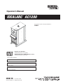
Lincoln Electric AC-1200 Operating instructions
- Category
- Welding System
- Type
- Operating instructions

IDEALARC
®
AC1200
Operator’s Manual
Save for future reference
Date Purchased
Code: (ex: 10859)
Serial: (ex: U1060512345)
IM10119 | Issue D ate 12-Oct
© Lincoln Global, Inc. All Rights Reserved.
For use with machines having Code Numbers:
11869
Register your machine:
www.lincolnelectric.com/register
Authorized Service and Distributor Locator:
www.lincolnelectric.com/locator

THANK YOU FOR SELECTING
A QUALITY PRODUCT BY
LINCOLN ELEC TRIC.
PLEASE EXAMINE CARTON AND EQUIPMENT FOR
DAMAGE IMMEDIATELY
When this equipment is shipped, title passes to the purchaser
upon receipt by the carrier. Consequently, claims for material
damaged in shipment must be made by the purchaser against the
transportation company at the time the shipment is received.
SAFETY DEPENDS ON YOU
Lincoln arc welding and cutting equipment is designed and built
with safety in mind. However, your overall safety can be increased
by proper installation ... and thoughtful operation on your part.
DO NOT INSTALL, OPERATE OR REPAIR THIS EQUIPMENT
WITHOUT READING THIS MANUAL AND THE SAFETY
PRECAUTIONS CONTAINED THROUGHOUT. And, most importantly,
think before you act and be careful.
This statement appears where the information must be followed
exactly to avoid serious personal injury or loss of life.
This statement appears where the information must be followed
to avoid minor personal injury or damage to this equipment.
KEEP YOUR HEAD OUT OF THE FUMES.
DON’T get too close to the arc.
Use corrective lenses if necessary
to stay a reasonable distance
away from the arc.
READ and obey the Safety Data
Sheet (SDS) and the warning label
that appears on all containers of
welding materials.
USE ENOUGH VENTILATION or
exhaust at the arc, or both, to
keep the fumes and gases from
your breathing zone and the general area.
IN A LARGE ROOM OR OUTDOORS, natural ventilation may be
adequate if you keep your head out of the fumes (See below).
USE NATURAL DRAFTS or fans to keep the fumes away
from your face.
If you de velop unusual symptoms, see your supervisor.
Perhaps the welding atmosphere and ventilation system
should be checked.
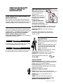
WEAR CORRECT EYE, EAR &
BODY PROTECTION
PROTECT your eyes and face with welding helmet
properly fitted and with proper grade of filter plate
(See ANSI Z49.1).
PROTECT your body from welding spatter and arc
flash with protective clothing including woolen
clothing, flame-proof apron and gloves, leather
leggings, and high boots.
PROTECT others from splatter, flash, and glare
with protective screens or barriers.
IN SOME AREAS, protection from noise may be appropriate.
BE SURE protective equipment is in good condition.
Also, wear safety glasses in work area
AT ALL TIMES.
SPECIAL SITUATIONS
DO NOT WELD OR CUT containers or materials which previously
had been in contact with hazardous substances unless they are
properly cleaned. This is extremely dangerous.
DO NOT WELD OR CUT painted or plated parts unless special
precautions with ventilation have been taken. They can release
highly toxic fumes or gases.
Additional precautionary measures
PROTECT compressed gas cylinders from excessive heat,
mechanical shocks, and arcs; fasten cylinders so they cannot fall.
BE SURE cylinders are never grounded or part of an
electrical circuit.
REMOVE all potential fire hazards from welding area.
ALWAYS HAVE FIRE FIGHTING EQUIPMENT READY FOR
IMMEDIATE USE AND KNOW HOW TO USE IT.
WARNING
CAUTION
Safety 01 of 04 - 5/16/2018

SECTION A:
WARNINGS
CALIFORNIA PROPOSITION 65 WARNINGS
WARNING: Breathing diesel engine exhaust
exposes you to chemicals known to the State
of California to cause cancer and birth defects,
or other reproductive harm.
• Always start and operate the engine in a
well-ventilated area.
• If in an exposed area, vent the exhaust to the outside.
• Do not modify or tamper with the exhaust system.
• Do not idle the engine except as necessary.
For more information go to
www.P65 warnings.ca.gov/diesel
WARNING: This product, when used for welding or
cutting, produces fumes or gases which contain
chemicals known to the State of California to cause
birth defects and, in some cases, cancer. (California
Health & Safety Code § 25249.5 et seq.)
WARNING: Cancer and Reproductive Harm
www.P65warnings.ca.gov
ARC WELDING CAN BE HAZARDOUS. PROTECT
YOURSELF AND OTHERS FROM POSSIBLE SERIOUS
INJURY OR DEATH. KEEP CHILDREN AWAY.
PACEMAKER WEARERS SHOULD CONSULT WITH
THEIR DOCTOR BEFORE OPERATING.
Read and understand the following safety highlights. For
additional safety information, it is strongly recommended
that you purchase a copy of “Safety in Welding & Cutting -
ANSI Standard Z49.1” from the American Welding Society,
P.O. Box 351040, Miami, Florida 33135 or CSA Standard
W117.2-1974. A Free copy of “Arc Welding Safety” booklet
E205 is available from the Lincoln Electric Company,
22801 St. Clair Avenue, Cleveland, Ohio 44117-1199.
BE SURE THAT ALL INSTALLATION, OPERATION,
MAINTENANCE AND REPAIR PROCEDURES ARE
PERFORMED ONLY BY QUALIFIED INDIVIDUALS.
FOR ENGINE POWERED
EQUIPMENT.
1.a. Turn the engine off before troubleshooting
and maintenance work unless the
maintenance work requires it to be running.
1.b. Operate engines in open, well-ventilated areas or vent the engine
exhaust fumes outdoors.
1.c. Do not add the fuel near an open flame welding
arc or when the engine is running. Stop the
engine and allow it to cool before refueling to
prevent spilled fuel from vaporizing on contact
with hot engine parts and igniting. Do not spill fuel when filling
tank. If fuel is spilled, wipe it up and do not start engine until
fumes have been eliminated.
1.d. Keep all equipment safety guards, covers
and devices in position and in good repair.
Keep hands, hair, clothing and tools away
from V-belts, gears, fans and all other
moving parts when starting, operating or
repairing equipment.
1.e. In some cases it may be necessary to remove safety guards to
perform required maintenance. Remove guards only when
necessary and replace them when the maintenance requiring
their removal is complete. Always use the greatest care when
working near moving parts.
1.f. Do not put your hands near the engine fan. Do not attempt to
override the governor or idler by pushing on the throttle control
rods while the engine is running.
1.g. To prevent accidentally starting gasoline engines while turning
the engine or welding generator during maintenance work,
disconnect the spark plug wires, distributor cap or magneto wire
as appropriate.
1.h. To avoid scalding, do not remove the radiator
pressure cap when the engine is
hot.
ELECTRIC AND
MAGNETIC FIELDS MAY
BE DANGEROUS
2.a. Electric current flowing through any conductor
causes localized Electric and Magnetic Fields (EMF).
Welding current creates EMF fields around welding cables
and welding machines
2.b. EMF fields may interfere with some pacemakers, and
welders having a pacemaker should consult their physician
before welding.
2.c. Exposure to EMF fields in welding may have other health effects
which are now not known.
2.d. All welders should use the following procedures in order to
minimize exposure to EMF fields from the welding circuit:
2.d.1. Route the electrode and work cables together - Secure
them with tape when possible.
2.d.2. Never coil the electrode lead around your body.
2.d.3. Do not place your body between the electrode and work
cables. If the electrode cable is on your right side, the
work cable should also be on your right side.
2.d.4. Connect the work cable to the workpiece as close as pos-
sible to the area being welded.
2.d.5. Do not work next to welding power source.
SAFETY
Safety 02 of 04 - 5/16/2018

ELECTRIC SHOCK
CAN KILL.
3.a. The electrode and work (or ground) circuits are
electrically “hot” when the welder is on. Do
not touch these “hot” parts with your bare skin or wet clothing.
Wear dry, hole-free gloves to insulate hands.
3.b. Insulate yourself from work and ground using dry insulation.
Make certain the insulation is large enough to cover your full area
of physical contact with work and ground.
In addition to the normal safety precautions, if
welding must be performed under electrically
hazardous conditions (in damp locations or while
wearing wet clothing; on metal structures such as
floors, gratings or scaffolds; when in cramped
positions such as sitting, kneeling or lying, if there
is a high risk of unavoidable or accidental contact
with the workpiece or ground) use the following
equipment:
• Semiautomatic DC Constant Voltage (Wire) Welder.
• DC Manual (Stick) Welder.
• AC Welder with Reduced Voltage Control.
3.c. In semiautomatic or automatic wire welding, the electrode,
electrode reel, welding head, nozzle or semiautomatic welding
gun are also electrically “hot”.
3.d. Always be sure the work cable makes a good electrical
connection with the metal being welded. The connection should
be as close as possible to the area being welded.
3.e. Ground the work or metal to be welded to a good electrical (earth)
ground.
3.f. Maintain the electrode holder, work clamp, welding cable and
welding machine in good, safe operating condition. Replace
damaged insulation.
3.g. Never dip the electrode in water for cooling.
3.h. Never simultaneously touch electrically “hot” parts of electrode
holders connected to two welders because voltage
between the
two can be the total of the open circuit voltage of both
welders.
3.i. When working above floor level, use a safety belt to protect
yourself from a fall should you get a shock.
3.j. Also see It ems 6.c. and 8.
ARC RAYS CAN BURN.
4.a. Use a shield with the proper filter and cover plates to protect your
eyes from sparks and the rays of the arc when welding or
observing open arc welding. Headshield and filter lens should
conform to ANSI Z87. I standards.
4.b. Use suitable clothing made from durable flame-resistant material
to protect your skin and that of your helpers from the arc rays.
4.c. Protect other nearby personnel with suitable, non-flammable
screening and/or warn them not to watch the arc nor expose
themselves to the arc rays or to hot spatter or metal.
FUMES AND GASES
CAN BE DANGEROUS.
5.a. Welding may produce fumes and gases
hazardous to health. Avoid breathing these
fumes and gases. When welding, keep your head out of the fume.
Use enough ventilation and/or exhaust at the arc to keep fumes
and gases away from the breathing zone. When welding
hardfacing (see instructions on container or SDS)
or on lead or cadmium plated steel and other
metals or coatings which produce highly toxic
fumes, keep exposure as low as possible and
within applicable OSHA PEL and ACGIH TLV limits
using local exhaust or mechanical ventilation
unless exposure assessments indicate otherwise.
In confined spaces or in some circumstances,
outdoors, a respirator may also be required.
Additional precautions are also required when
welding
on galvanized steel.
5. b. The operation of welding fume control equipment is affected by
various factors including proper use and positioning of the
equipment, maintenance of the equipment and the specific
welding procedure and application involved. Worker exposure
level should be checked upon installation and periodically
thereafter to be certain it is within applicable OSHA PEL and
ACGIH TLV limits.
5.c. Do not weld in locations near chlorinated hydrocarbon vapors
coming from degreasing, cleaning or spraying operations. The
heat and rays of the arc can react with solvent vapors to form
phosgene, a highly toxic gas, and other irritating products.
5.d. Shielding gases used for arc welding can displace air and
cause
injury or death. Always use enough ventilation, especially in
confined areas, to insure breathing air is safe.
5.e. Read and understand the manufacturer’s instructions for this
equipment and the consumables to be used, including the
Safety Data Sheet (SDS) and follow your employer’s safety
practices. SDS forms are available from your welding
distributor or from the manufacturer.
5.f. Also see item 1.b.
SAFETY
Safety 03 of 04 - 5/16/2018

WELDING AND CUTTING
SPARKS CAN CAUSE
FIRE OR EXPLOSION.
6.a. Remove fire hazards from the welding area. If
this is not possible, cover them to prevent the welding sparks
from starting a fire. Remember that welding sparks and hot
materials from welding can easily go through small cracks and
openings to adjacent areas. Avoid welding near hydraulic lines.
Have a fire extinguisher readily available.
6.b. Where compressed gases are to be used at the job site, special
precautions should be used to prevent hazardous situations.
Refer to “Safety in Welding and Cutting” (ANSI Standard Z49.1)
and the operating information for the equipment being used.
6.c. When not welding, make certain no part of the electrode circuit is
touching the work or ground. Accidental contact can cause
overheating and create a fire hazard.
6.d. Do not heat, cut or weld tanks, drums or containers until the
proper steps have been taken to insure that such procedures
will not cause flammable or toxic vapors from substances inside.
They can cause an explosion even though they have been
“cleaned”. For information, purchase “Recommended Safe
Practices for the Preparation for Welding and Cutting of
Containers and Piping That Have Held Hazardous Substances”,
AWS F4.1 from the American Welding Society
(see address above).
6.e. Vent hollow castings or containers before heating, cutting or
welding. They may explode.
6.f. Sparks and spatter are thrown from the welding arc. Wear oil free
protective garments such as leather gloves, heavy shirt, cuffless
trousers, high shoes and a cap over your hair. Wear ear plugs
when welding out of position or in confined places. Always wear
safety glasses with side shields when in a welding area.
6.g. Connect the work cable to the work as close to the welding area
as practical. Work cables connected to the building framework or
other locations away from the welding area increase the
possibility of the welding current passing through lifting chains,
crane cables or other alternate circuits. This can create fire
hazards or overheat lifting chains or cables until they fail.
6.h. Also see item 1.c.
6.I. Read and follow NFPA 51B “Standard for Fire Prevention During
Welding, Cutting and Other Hot Work”, available from NFPA, 1
Batterymarch Park, PO box 9101, Quincy, MA 022690-9101.
6.j. Do not use a welding power source for pipe thawing.
CYLINDER MAY EXPLODE IF
DAMAGED.
7.a. Use only compressed gas cylinders containing
the correct shielding gas for the process used
and properly operating regulators designed for
the gas and pressure used. All hoses, fittings,
etc. should be suitable for the application and
maintained in good condition.
7.b. Always keep cylinders in an upright position securely chained to
an undercarriage or fixed support.
7.c. Cylinders should be located:
• Away from areas where they may be struck or subjected
to physical damage.
• A safe distance from arc welding or cutting operations
and any other source of heat, sparks, or flame.
7.d. Never allow the electrode, electrode holder or any other
electrically “hot” parts to touch a cylinder.
7.e. Keep your head and face away from the cylinder valve outlet
when opening the cylinder valve.
7.f. Valve protection caps should always be in place and hand tight
except when the cylinder is in use or connected for use.
7.g. Read and follow the instructions on compressed gas cylinders,
associated equipment, and CGA publication P-l, “Precautions for
Safe Handling of Compressed Gases in Cylinders,” available from
the Compressed Gas Association, 14501 George Carter Way
Chantilly, VA 20151.
FOR ELECTRICALLY
POWERED EQUIPMENT.
8.a. Turn off input power using the disconnect
switch at the fuse box before working on
the equipment.
8.b. Install equipment in accordance with the U.S. National Electrical
Code, all local codes and the manufacturer’s recommendations.
8.c. Ground the equipment in accordance with the U.S. National
Electrical Code and the manufacturer’s recommendations.
Refer to
http://www.lincolnelectric.com/safety
for additional safety information.
SAFETY
Safety 04 of 04 - 5/16/2018

iv
SAFETY
iv
PRÉCAUTIONS DE SÛRETÉ
Pour votre propre protection lire et observer toutes les instructions
et les précautions de sûreté specifiques qui parraissent dans ce
manuel aussi bien que les précautions de sûreté générales suiv-
antes:
Sûreté Pour Soudage A LʼArc
1. Protegez-vous contre la secousse électrique:
a. Les circuits à lʼélectrode et à la piéce sont sous tension
quand la machine à souder est en marche. Eviter toujours
tout contact entre les parties sous tension et la peau nue
ou les vétements mouillés. Porter des gants secs et sans
trous pour isoler les mains.
b. Faire trés attention de bien sʼisoler de la masse quand on
soude dans des endroits humides, ou sur un plancher
metallique ou des grilles metalliques, principalement dans
les positions assis ou couché pour lesquelles une grande
partie du corps peut être en contact avec la masse.
c. Maintenir le porte-électrode, la pince de masse, le câble
de soudage et la machine à souder en bon et sûr état
defonctionnement.
d.Ne jamais plonger le porte-électrode dans lʼeau pour le
refroidir.
e. Ne jamais toucher simultanément les parties sous tension
des porte-électrodes connectés à deux machines à souder
parce que la tension entre les deux pinces peut être le
total de la tension à vide des deux machines.
f. Si on utilise la machine à souder comme une source de
courant pour soudage semi-automatique, ces precautions
pour le porte-électrode sʼapplicuent aussi au pistolet de
soudage.
2. Dans le cas de travail au dessus du niveau du sol, se protéger
contre les chutes dans le cas ou on recoit un choc. Ne jamais
enrouler le câble-électrode autour de nʼimporte quelle partie
du corps.
3. Un coup dʼarc peut être plus sévère quʼun coup de soliel,
donc:
a. Utiliser un bon masque avec un verre filtrant approprié
ainsi quʼun verre blanc afin de se protéger les yeux du ray-
onnement de lʼarc et des projections quand on soude ou
quand on regarde lʼarc.
b. Porter des vêtements convenables afin de protéger la
peau de soudeur et des aides contre le rayonnement de
lʻarc.
c. Protéger lʼautre personnel travaillant à proximité au
soudage à lʼaide dʼécrans appropriés et non-inflammables.
4. Des gouttes de laitier en fusion sont émises de lʼarc de
soudage. Se protéger avec des vêtements de protection libres
de lʼhuile, tels que les gants en cuir, chemise épaisse, pan-
talons sans revers, et chaussures montantes.
5. Toujours porter des lunettes de sécurité dans la zone de
soudage. Utiliser des lunettes avec écrans lateraux dans les
zones où lʼon pique le laitier.
6. Eloigner les matériaux inflammables ou les recouvrir afin de
prévenir tout risque dʼincendie dû aux étincelles.
7. Quand on ne soude pas, poser la pince à une endroit isolé de
la masse. Un court-circuit accidental peut provoquer un
échauffement et un risque dʼincendie.
8. Sʼassurer que la masse est connectée le plus prés possible
de la zone de travail quʼil est pratique de le faire. Si on place
la masse sur la charpente de la construction ou dʼautres
endroits éloignés de la zone de travail, on augmente le risque
de voir passer le courant de soudage par les chaines de lev-
age, câbles de grue, ou autres circuits. Cela peut provoquer
des risques dʼincendie ou dʼechauffement des chaines et des
câbles jusquʼà ce quʼils se rompent.
9. Assurer une ventilation suffisante dans la zone de soudage.
Ceci est particuliérement important pour le soudage de tôles
galvanisées plombées, ou cadmiées ou tout autre métal qui
produit des fumeés toxiques.
10. Ne pas souder en présence de vapeurs de chlore provenant
dʼopérations de dégraissage, nettoyage ou pistolage. La
chaleur ou les rayons de lʼarc peuvent réagir avec les vapeurs
du solvant pour produire du phosgéne (gas fortement toxique)
ou autres produits irritants.
11. Pour obtenir de plus amples renseignements sur la sûreté,
voir le code “Code for safety in welding and cutting” CSA
Standard W 117.2-1974.
PRÉCAUTIONS DE SÛRETÉ POUR
LES MACHINES À SOUDER À
TRANSFORMATEUR ET À
REDRESSEUR
1. Relier à la terre le chassis du poste conformement au code de
lʼélectricité et aux recommendations du fabricant. Le dispositif
de montage ou la piece à souder doit être branché à une
bonne mise à la terre.
2. Autant que possible, Iʼinstallation et lʼentretien du poste seront
effectués par un électricien qualifié.
3. Avant de faires des travaux à lʼinterieur de poste, la debranch-
er à lʼinterrupteur à la boite de fusibles.
4. Garder tous les couvercles et dispositifs de sûreté à leur
place.

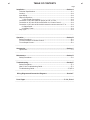
Page
Installation .......................................................................................................Section A
Technical Specifications ........................................................................................A-1
Location ................................................................................................................A-2
Input Wiring............................................................................................................A-2
Output Connections...............................................................................................A-2
1. Wire Feeder Connections ...........................................................................A-2
Connection of AC-1200 (with NL Option) to LAF or LT34 .....................................A-3
Connection of AC-1200 to NA-4 with Switch for ʻCurrent Controlʼ.........................A-3
Connection of AC-1200 to NA-4 with rheostat for current control or LT-6.............A-3
2. Output Studs ...............................................................................................A-4
3. Auxiliary Power ...........................................................................................A-4
Duty Cycle .............................................................................................................A-4
_______________________________________________________________________
Operation .........................................................................................................Section B
Safety Precautions.................................................................................................B-1
To set for machine or Remote Control...................................................................B-1
To set Output Current............................................................................................B-1
________________________________________________________________________
Accessories .....................................................................................................Section C
Optional Kit............................................................................................................C-1
________________________________________________________________________
Maintenance ....................................................................................................Section D
Safety Precautions ................................................................................................D-1
________________________________________________________________________
Troubleshooting..............................................................................................Section E
Safety Precautions.................................................................................................E-1
How to Use Troubleshooting Guide.......................................................................E-1
Troubleshooting Guide....................................................................................E-2,E-3
________________________________________________________________________
Wiring Diagram and Connection Diagrams .................................................Section F
________________________________________________________________________
Parts Pages............................................................................................... P-701, P-28-J
________________________________________________________________________
vi
vi
TABLE OF CONTENTS

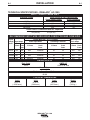
A-1
INSTALLATION
IDEALARC
®
AC-1200
A-1
Weight
1636 lbs.
(742 kg.)
INPUT - SINGLE PHASE ONLY
RATED OUTPUT
PHYSICAL DIMENSIONS
RECOMMENDED INPUT WIRE GROUNDING CONDUCTOR AND FUSE SIZES
Standard Voltage
Duty Cycle
100%
Current Range
240/1200
Maximum Open Circuit Voltage
Depth
38.00 in.
(965.2mm.)
Width
22.30 in.
(566.4mm.)
Height
53.50 in.
( 1358.9mm.)
AMPS AC
1200 @ 44 Volts
Input Current at 100% Rated Output
Single Phase Output Scott Connection
460/60
440/50/60
415/50/60
380/50/60
182 209
190 219
201 232
220 255
TECHNICAL SPECIFICATIONS - IDEALARC
®
AC-1200
86-88
RATING: IP21 ENCLOSURE
Power Factor @ Rated load With P.F. Capacitors
79%(60 Hz) 76%(50 Hz)
Input Copper Wire Size - 75˚C in Conduit Super Lag Fuses
Voltage/ Input Amps Power Input Wires Grounding Conductor Size in Amps
Hertz
1 Phase Scott 1 Phase Scott 1 Phase Scott 1 Phase Scott
Conn. Conn. Conn. Conn.
460/60 182 209 #4/0 250MCM #4 #3 300 350
440/50/60 190 219 #4/0 250MCM #4 #3 300 350
415/50/60 201 232 #4/0 300MCM #4 #3 300 350
380/50/60 220 255 250MCM 350MCM #3 #3 300 400

A-2
INSTALLATION
IDEALARC
®
AC-1200
A-2
LOCATION
Install the welder in a dry location where there is free
circulation of air in through the louvers in front and out
through the louvers in the back of the case. A location
which minimizes the amount of smoke and dirt drawn
into the machine reduces the chance of dirt accumula-
tion that can block air passages and cause overheat-
ing.
INPUT WIRING
Failure to fuse the input lines per the specifications
in this manual will constitute customer abuse and
void the warranty.
-----------------------------------------------------------------------------
Have a qualified electrician make the complete input
connection in accordance with the National Electrical
Code, all local codes and the connection diagram
located inside the machine.
Be sure the voltage, phase and frequency of the input
power
is as specified on the welder nameplate.
For most installations, connect the AC-1200 to single
phase power or to one phase of a three phase line.
Unbalanced line conditions can be easily avoided by
properly balancing the AC-1200 with other machinery
on the lines.
When installing two or four Scott connected AC-1200
machines for AC-AC tandem arc welding, three phase
input power must be used. The terminals for connec-
tions to provide an output phase angle less than or
greater than the usual 90º phase angle are included
on the input panel.
The AC-1200 does not have an input contactor.
Therefore, include an external starter or disconnect
switch when planning the input circuit.
Remove the right side panel of the AC-1200 and bring the
input power lines through the hole in the back of the case.
See the table below for reccomended sizing of input leads
and overcurrent protection.
The frame of the welder must be grounded, A stud marked
with the symbol located on the welder case back
hole in the back of the case is provided for this purpose.
See the National Electrical Code for details on proper
grounding methods.
OUTPUT CONNECTIONS
1. Wire Feeder Connection
Turn the input power to the welder off. Remove the
screw and lift the hinged door on the front of the control
panel to expose the terminal strips. Connect the leads of
the wire feeder input control cable to the terminal strips
exactly as specified in the appropriate connection diagram.
The AC-1200 to NA-4 connection diagrams are included
in the NA-4 Operating Manual IM-278. Attach the control
cables to the panel at the right of the terminal strip using
the clamps provided.
If connecting the AC-1200 to an older NA-4 with the tog-
gle switch type “Current Control” (below code 7532), a K-
775 “Remote Control” must be purchased and installed in
accordance with the connection diagram S-15667 on page
5. The “Remote Control” cord can be lengthened to any
length by properly splicing a four conductor cord to the
standard 25ʼ cord before connecting to the AC-1200 ter-
minal strip.
If connecting the AC-1200 to an LAF-4 or the AC con-
trols of the LT-34 tractor, the AC-1200 must be ordered
with the required “–NL” optional circuit installed. This kit
includes the K-775 “Remote Control”. Connect in accor-
dance with diagram S-15666 on page 5.
To connect the AC-1200 to any other wire feeder, write to
the factory for instructions giving complete nameplate infor-
mation for the specific equipment.
When connection to the terminal strips are completed,
close the door and replace the screw.
WARNING
ELECTRIC SHOCK
can kill.
• Have an electrician install
and service this equip-
ment.
• Turn the input power off at
the fuse box before work-
ing on equipment.
• Do not touch electrically
hot parts.

A-3
INSTALLATION
IDEALARC
®
AC-1200
A-3
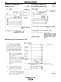
Connection of AC-1200 (with NL Option) S-15666
to LAF-4 or LT-34 4-18-75
Connection of AC-1200 to NA-4 S-15667
with Switch for ‘Current Control’ 4-18-75
Connection of AC-1200 to
NA-4 with rheostat for current control or LT-6.
S-15602
6-22-84H

A-4
INSTALLATION
IDEALARC
®
AC-1200
A-4
2. Output Studs
Connect the work cables to the “To Work” stud on
the front of the AC-1200. Connect the electrode
cables to the “Min”, “Med” or “Max” studs for the
output desired. Actual current ranges for each stud
are indicated on the nameplate above each stud.
Recommended cable sizes are listed below. Both
the “To Work” and “Max” studs have two terminals
to simplify connection of recommended cables in
parallel. Tighten the nuts with a wrench.
Select cables required for combined work and elec-
trode cable lengths up to 150ʼ from the following
table:
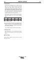
Maximum Allowable Current for Copper Welding Cable
Cables in accessory kit recommended below have
terminals as required to comply with applicable
U.L. standards for safety.
150ʼ combined length electrode and work cables.
3. Auxiliary Power
920 volt-amperes of 115 volt AC power are avail-
able from #31 and #32 on the AC-1200 terminal
strip.
DUTY CYCLE
The AC-1200 is rated for 100% duty cycle at 1200
amps and 44 volts.
Duty
Cycle One 4/0 Two 4/0 Three 4/0 Four 4/0
100% 500 930 1150 1350
80%* 560 1040 1290 1510
* Based on 10 minute cycle.

B-1
OPERATION
IDEALARC
®
AC-1200
B-1
TO SET FOR LOCAL OR REMOTE
CONTROL
The output can be controlled either from the AC-
1200, the wire feeder or other remote locations.
To adjust the current from the wire feeder or other
remote locations, set the toggle switch on the front of
the AC-1200 to “ “. To adjust the output current
from the AC-1200, set this switch to “ “.
T0 SET THE OUTPUT CURRENT
Start the AC-1200 using the line disconnect switch or
breaker installed with the input wiring. The yellow pilot
light on the front panel indicates when the welder is
on.
Adjust the output current from minimum to maximum
within the range set by the output stud connections
using either the “ “ rheostat on the AC-1200 (tog-
gle switch set on “ “) or the wire feeder or other
remote rheostat (toggle switch set on “ “).
ELECTRIC SHOCK
can kill.
• Do not touch electrically live parts
or electrode with skin or wet
clothing.
• Insulate yourself from work and
ground.
• Always wear dry insulating
gloves.
FUMES AND GASES
can be dangerous.
• Keep your head out of fumes.
• Use ventilation or exhaust to
remove fumes from breathing
zone.
WELDING SPARKS
can cause fire or
explosion
• Keep flammable material away.
• Do not weld on containers that
have held combustibles.
ARC RAYS
can burn.
• Wear eye, ear and body
protection.
SAFETY PRECAUTIONS
Read and understand this entire section before oper-
ating the machine.
Observe additional Safety Guidelines detailed
throughout this manual.
WARNING
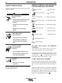
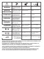
GRAPHIC SYMBOLS THAT APPEAR ON
THIS MACHINE OR IN THIS MANUAL
Output Control 1 Single Phase
Remote Control Setting
3
Three Phase
Local Control Settin
Uo
Rated No-Load Voltage
Input Power Type U1 Rated Input Voltage
Submerged Arc Welding
U2
Rated Welding Voltage
Transformer Type X Rated Duty Cycle
Fuse
I1
Rated Input Current
High Voltage Indicator
I2
Rated Welding Current
High Temperature Indicator
Rated Frequency

C-1
ACCESSORIES
C-1
OPTIONAL KIT: Remote control K775.
IDEALARC
®
AC-1200

D-1
MAINTENANCE
D-1
IDEALARC
®
AC-1200
SAFETY PRECAUTIONS
ELECTRIC SHOCK can kill.
• Have qualified personnel do the
maintenance and troubleshooting
work.
• Turn the input power OFF at the disconnect
switch or fuse box before working on this
equipment.
• Do not touch electrically live parts or electrode
with skin or wet clothing.
• Insulate yourself from work and ground.
• Always wear dry insulating gloves.
------------------------------------------------------------------------
See additional warning information
throughout this operatorʼs manual.
------------------------------------------------------------
1. Every three months, blow out the machine with
compressed air. More frequent cleaning may be
necessary in areas with chemical or metallic parti-
cles and large quantities of dust.
2. The fan motors have sealed bearings which require
no service.
WARNING

E-1
TROUBLESHOOTING
E-1
IDEALARC
®
AC-1200
If for any reason you do not understand the test procedures or are unable to perform the tests/repairs safely, contact your
Local Lincoln Authorized Field Service Facility for technical troubleshooting assistance before you proceed.
CAUTION
This Troubleshooting Guide is provided to help you
locate and repair possible machine malfunctions.
Simply follow the three-step procedure listed below.
Step 1. LOCATE PROBLEM (SYMPTOM).
Look under the column labeled “PROBLEM (SYMP-
TOMS)”. This column describes possible symptoms
that the machine may exhibit. Find the listing that
best describes the symptom that the machine is
exhibiting.
Step 2. POSSIBLE CAUSE.
The second column labeled “POSSIBLE CAUSE” lists
the obvious external possibilities that may contribute
to the machine symptom.
Step 3. RECOMMENDED COURSE OF ACTION
This column provides a course of action for the
Possible Cause, generally it states to contact your
local Lincoln Authorized Field Service Facility.
If you do not understand or are unable to perform the
Recommended Course of Action safely, contact your
local Lincoln Authorized Field Service Facility.
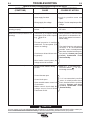
HOW TO USE TROUBLESHOOTING GUIDE
Service and Repair should only be performed by Lincoln Electric Factory Trained Personnel.
Unauthorized repairs performed on this equipment may result in danger to the technician and
machine operator and will invalidate your factory warranty. For your safety and to avoid Electrical
Shock, please observe all safety notes and precautions detailed throughout this manual.
__________________________________________________________________________
WARNING

E-2
TROUBLESHOOTING
E-2
IDEALARC
®
AC-1200
Observe all Safety Guidelines detailed throughout this manual
If for any reason you do not understand the test procedures or are unable to perform the tests/repairs safely, contact your
Local Lincoln Authorized Field Service Facility for technical troubleshooting assistance before you proceed.
CAUTION
PROBLEMS
(SYMPTOMS)
POSSIBLE
CAUSE
RECOMMENDED
COURSE OF ACTION
Welder will not start.
Welder will not weld (Contactors
operating properly)
Welder will not weld (Contactors not
operating).
Welder welds at min. only no control.
1. Supply line fuse blown.
2. Open supply line lead.
3. Wrong supply line voltage.
1. Electrode or ground cable loose or
broken.
1. Thermostat on coil tripped. Welder
overheated (Fan motors operat-
ing). light is on.
2. Thermal protection in auxiliary
transformer, T2, has opened. (Fan
motors not running)
3. Circuit across #2 and #4 not work-
ing properly.
4. Wire feeder control power; No
voltage across #31 and #32.
1. Remote control switch in wrong
position.
2. Control rheostat open.
3. Control circuit open.
4. Open saturable reactor control coil
or connection.
5. Welder control circuit dead: No
voltage across Control Board
Transformer X1-X2.
1. Replace fuse.
2. Look for possible cause and
repair.
3. Repair.
Provide nameplate specified
voltage.
1. Tighten connection or repair bro-
ken cable.
1. Check operation of fans and make
sure there is no obstruction to air
flow. Do not operate in excess of
welder rating.
First check 8 Amp fuse and replace if
necessary. I
f all recommended
possible areas of misadjustment
have been checked and the prob-
lem persists, Contact your local
Lincoln Authorized Field
Service Facility.
1. Switch to “ “ for welder rheo-
stat control and to “ ” for con-
trol through accessory.
I
f all recommended possible
areas of misadjustment have
been checked and the problem
persists, Contact your local
Lincoln Authorized Field
Service Facility.

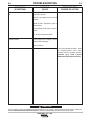
E-3
TROUBLESHOOTING
E-3
IDEALARC
®
AC-1200
If for any reason you do not understand the test procedures or are unable to perform the tests/repairs safely, contact your
Local Lincoln Authorized Field Service Facility for technical troubleshooting assistance before you proceed.
CAUTION
PROBLEMS
(SYMPTOMS)
POSSIBLE
CAUSE
RECOMMENDED
COURSE OF ACTION
Welder welds at max. only no con-
trol.
Contacts chatter.
Diodes or SCRʼs on heat sink
assemblies shorted.
Shorted or grounded current controll
rheostat.
Output By-Pass Capacitors open or
disconnected.
Free wheeling diode open or discon-
nected.
P.C. board components failed.
1. Low supply line voltage. Check
with Power Company.
Faulty contactor.
I
f all recommended possible areas
of misadjustment have been
checked and the problem persists,
Contact your local Lincoln
Authorized Field Service Facility.

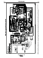
F-1
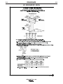
DIAGRAMS
F-1
IDEALARC
®
AC-1200
NOTE: This diagram is for reference only. It may not be accurate for all machines covered by this manual. The specific diagram for a particular code is pasted inside the
machine on one of the enclosure panels. If the diagram is illegible, write to the Service Department for a replacement. Give the equipment code number.

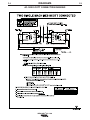
F-2
DIAGRAMS
F-2
IDEALARC
®
AC-1200
AC-1200 SCOTT CONNECTION DIAGRAM

F-3
DIAGRAMS
F-3
IDEALARC
®
AC-1200
M10033-1
A.01
100
90
80
L2
L1
L2
L1
P1
CB
A
TO GROUND PER NATIONAL
ELECTRIC CODE.
WORK
ELECTRODE
WORK
ELECTRODE
N.B.
MAIN TRANSFORMER
LEAD ARC
4/O CABLES
4/O CABLE
N.C.
TEASER TRANSFORMER
TRAIL ARC
4/O CABLES
4/O CABLE
N.C.
100
90
80
L2
L1
L2
L1
P1
CBA
TO GROUND PER NATIONAL
ELECTRIC CODE.
WORK
ELECTRODE
WORK
ELECTRODE
N.B.
N.B.
N.B.
3 PHASE SUPPLY LINE (N.A.)
NOTES:
N.B. ELECTRODE CABLES OF PARALLELED MACHINES SHOULD BE CONNECTED TO THE SAME RANGE TAP.
N.C. NUMBER OF 4/O CABLES CONNECTED: 1 ON MIN. TAP; 2 PARALLEL ON MED. TAP; 3 PARALLEL ON MAX. TAP.
TWO PARALLEL MACHINES SCOTT CONNECTED TO TWO OTHER PARALLEL MACHINES
FOR DESIRED PHASE ANGLE, INTERCONNECT MACHINES (AS SHOWN BELOW).
BOTH PHASE ANGLES MUST BE THE SAME.
N.A. TO OBTAIN NORMAL PHASE SEQUENCE AT THE WELDING ARCS, THE INPUT LINE PHASE SEQUENCE SHOULD BE A-C-B.
AC-1200 SCOTT CONNECTION DIAGRAM
Page is loading ...
Page is loading ...
Page is loading ...
Page is loading ...
Page is loading ...
-
 1
1
-
 2
2
-
 3
3
-
 4
4
-
 5
5
-
 6
6
-
 7
7
-
 8
8
-
 9
9
-
 10
10
-
 11
11
-
 12
12
-
 13
13
-
 14
14
-
 15
15
-
 16
16
-
 17
17
-
 18
18
-
 19
19
-
 20
20
-
 21
21
-
 22
22
-
 23
23
-
 24
24
-
 25
25


Lincoln Electric AC-1200 Operating instructions
- Category
- Welding System
- Type
- Operating instructions
Ask a question and I''ll find the answer in the document
Finding information in a document is now easier with AI
in other languages
- français: Lincoln Electric AC-1200 Mode d'emploi
Related papers
-
HP 500au User manual
-
Lincoln Electric Air Vantage 500 Operating instructions
-
-
-
-
-
-
-
-
