KitchenAid KFGC500JAV Installation guide
- Category
- Cookers
- Type
- Installation guide

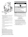
INSTALLATION INSTRUCTIONS
CommerCial-Style GaS ranGeS
30" (76.2 Cm), 36" (91.4 Cm), and 48" (121.9 Cm)
For residential use only
INSTRUCTIONS D’INSTALLATION
CuiSinière à Gaz de Style CommerCial de
30 po (76,2 Cm), 36 po (91,4 Cm) et 48 po (121,9 Cm)
Pour utilisation résidentielle uniquement
Table of Contents/Table des matières
W11177374A
RANGE SAFETY .............................................................................2
INSTALLATION REQUIREMENTS ................................................. 4
Tools and Parts .............................................................................4
Location Requirements ................................................................5
Electrical Requirements ...............................................................7
Gas Supply Requirements ...........................................................7
INSTALLATION INSTRUCTIONS ................................................... 9
Unpack the Range .......................................................................9
Remove Door ...............................................................................9
Install Anti-Tip Bracket ...............................................................10
Make Gas Connection ...............................................................11
Verify Anti-Tip Bracket Location ................................................12
Install Griddle Tray ......................................................................12
Electronic Ignition System .........................................................12
Level Range ................................................................................13
Install Kick Plate .........................................................................13
Complete Installation .................................................................13
GAS CONVERSIONS ....................................................................14
Propane Gas Conversion ...........................................................14
Natural Gas Conversion .............................................................17
IMPORTANT:
Save for local electrical inspector’s use.
Installer: Leave installation instructions with the homeowner.
Homeowner: Keep installation instructions for future reference.
IMPORTANT:
Conserver ces instructions à l’usage de l’inspecteur des installations électriques local.
Installateur: Remettre les instructions d’installation au propriétaire.
Propriétaire: Conserver les instructions d’installation pour référence ultérieure.
www.kitchenaid.com (U.S.A.) www.kitchenaid.ca (Canada)
SÉCURITÉ DE LA CUISINIÈRE ...................................................21
EXIGENCES D’INSTALLATION ...................................................23
Outils et pièces ...........................................................................23
Exigences d’emplacement .........................................................24
Spécications électriques ..........................................................26
Spécications de l’alimentationen gaz .....................................27
INSTRUCTIONS D’INSTALLATION .............................................29
Déballage de la cuisinière ..........................................................29
Retirer la porte ............................................................................29
Installation de la bride antibasculement ....................................30
Raccordement au gaz ................................................................31
Vérication de l’emplacement dela bride antibasculement ......32
Installer le plateau d’égouttement .............................................32
Système d’allumage électronique..............................................32
Ajustement de l’aplomb delacuisinière ....................................33
Installer la plinthe .......................................................................33
Terminer l’installation .................................................................. 33
CONVERSIONS POUR CHANGEMENT DE GAZ ......................34
Conversion pour l’alimentation aupropane ..............................34
Conversion au gaz naturel .........................................................37

2
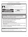
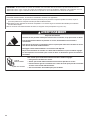
RANGE SAFETY
WARNING: If the information in these instructions is not followed exactly, a fire or
explosion may result causing property damage, personal injury or death.
– Do not store or use gasoline or other flammable vapors and liquids in the vicinity of this
or any other appliance.
– WHAT TO DO IF YOU SMELL GAS:
•
Do not try to light any appliance.
•
Do not touch any electrical switch.
•
Do not use any phone in your building.
•
Immediately call your gas supplier from a neighbor's phone. Follow the gas supplier's
instructions.
•
If you cannot reach your gas supplier, call the fire department.
– Installation and service must be performed by a qualified installer, service agency or
the gas supplier.
WARNING: Gas leaks cannot always be detected by smell.
Gas suppliers recommend that you use a gas detector approved by UL or CSA.
For more information, contact your gas supplier.
If a gas leak is detected, follow the “What to do if you smell gas” instructions.

3
IMPORTANT: Do not install a ventilation system that blows air downward toward this gas cooking appliance. This type of
ventilation system may cause ignition and combustion problems with this gas cooking appliance resulting in personal injury or
unintended operation.
In the State of Massachusetts, the following installation instructions apply:
■ Installations and repairs must be performed by a qualified or licensed contractor, plumber, or gas fitter qualified or licensed by
the State of Massachusetts.
■ Acceptable Shut-off Devices: Gas Cocks and Ball Valves installed for use shall be listed.
■ A flexible gas connector, when used, must not exceed 4 feet (121.9 cm).
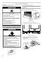
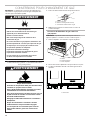
Tip Over Hazard
A child or adult can tip the range and be killed.
Install anti-tip bracket to floor or wall per installation instructions.
Slide range back so rear range foot is engaged in the slot of the anti-tip bracket.
Re-engage the anti-tip bracket if the range is moved.
Do not operate range without anti-tip bracket installed and engaged.
Failure to follow these instructions can result in death or serious burns to children and adults.
Anti-Tip
Bracket
To verify the anti-tip bracket is installed and engaged:
• Slide range forward.
• Look for the anti-tip bracket securely attached to floor or wall.
• See installation instructions for details.
Range Foot
WARNING
Slide range back so rear range foot is under anti-tip bracket.•

4
INSTALLATION REQUIREMENTS
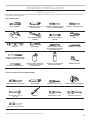
Tools and Parts
Gather the required tools and parts before starting installation. Read and follow the instructions provided with any tools listed here.
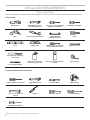
Tools Needed
For Propane/Natural Gas Conversions
Large at-blade screwdriver Adjustable wrench 7 mm Nut Driver Masking tape
1/2" (1.3 cm) open end
wrench
Lighter T20
®
Torx
®†
Driver #1 Square Drive
#2 Phillips Screwdriver
Pipe wrench Adjustable wrench or
5/8"(16mm) wrench
1/8" x 4
1
/
4
" (3mmx100mm)
at-blade screwdriver
#2 Phillips screwdriver
Drill 3/8" (9.5 mm) drive ratchet 15/16" (24 mm)
combinationwrench
Pliers
Level Tubing cutter 1/4" (6.4 mm), 3/8" (9.5 mm),
5/16" (7.9 mm) nut drivers
Marker or pencil
3/16" (4.8 mm) carbide tip
masonry bit
1/8" (3.2 mm) drill bit
Pipe-joint compound
resistanttopropanegas
Noncorrosive leak-detection
solution
Tape measure
†
®
TORX and T20 are trademarks of Acument Intellectual Properties, LLC.

5
Parts Supplied
Check that all parts are included.
■ Anti-tip bracket kit
NOTE: Anti-tip bracket must be securely mounted to
suboor. Thickness of ooring may require longer screws
toanchor bracket to suboor. Longer screws are available
from your local hardware store. See the “Install Anti-Tip
Bracket” section.
■ Burner grates
■ Burner caps
■ Griddle drip tray (on griddle models)
Parts Needed
■ All models must be installed with a backguard if installing
at zero clearance to a combustible back wall surface such
as drywall. See “Cabinet Dimensions” in the “Location
Requirements” section for installation requirements.
Check local codes and consult gas supplier. Check existing gas
supply and electrical supply. See the “Electrical Requirements”
and “Gas Supply Requirements” sections.
It is recommended that all electrical connections be made by
alicensed, qualied electrical installer.
High Altitude Conversion
To convert the range for elevations above 6,560 ft (2000 m),
order a High Altitude Conversion Kit.
■ High Altitude Kit W11238044
NOTE: Both propane and natural gas conversions are included
in the high altitude kit.
To order, see the “Assistance or Service” section of the Use
andCare Guide.
Location Requirements
IMPORTANT: Observe all governing codes and ordinances.
Donot obstruct ow of combustion and ventilation air.
■ It is the installer’s responsibility to comply with installation
clearances specied on the model/serial/rating plate. The
model/serial/rating plate is located under the console on
theright-hand side.
■ It is recommended that a 600 CFM (17.0 m
3
/hr) or larger
range hood beinstalled above the range.
■ Follow the range hood or microwave hood combination
installation instructions for dimensional clearances above the
cooktop surface.
■ Recessed installations must provide complete enclosure
ofthe sides and rear of the range.
■ All openings in the wall or oor where range is to be installed
must be sealed.
■ Do not seal the range to the side cabinets.
■ Cabinet opening dimensions that are shown must be used.
Given dimensions are minimum clearances.
■ The anti-tip bracket must be installed. To install the anti-tip
bracket shipped with the range, see the “Install Anti-Tip
Bracket” section.
■ Grounded electrical supply is required. See the “Electrical
Requirements” section.
■ Proper gas supply connection must be available. See the
“Gas Supply Requirements” section.
■ Contact a qualied oor covering installer to check that the
oor covering can withstand at least 200°F (93°C). Use an
insulated pad or 1/4" (6.4 mm) plywood over carpet and
under range if installing range over carpeting.
IMPORTANT: To avoid damage to your cabinets, check with
your builder or cabinet supplier to make sure that the materials
used will not discolor, delaminate, or sustain other damage. This
oven has been designed in accordance with the requirements
of UL and CSA International and complies with the maximum
allowable wood cabinet temperatures of 194°F (90°C).
Mobile Home - Additional Installation Requirements
The installation of this range must conform to the Manufactured
Home Construction and Safety Standard, Title24CFR,
Part 3280 (formerly the Federal Standard for Mobile Home
Construction and Safety, Title 24, HUD Part 280).When such
standard is not applicable, use the Standard forManufactured
Home Installations, ANSI A225.1/NFPA 501A or local codes.
In Canada, the installation of this range must conform with
thecurrent standards CAN/CSA-A240-latest edition or with
localcodes.
Mobile Home Installations Require:
■ When this range is installed in a mobile home, it must be
secured to the oor during transit. Any method of securing
the range is adequate as long as it conforms to the
standards listed above.
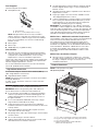
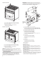
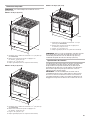
Product Dimensions
NOTE: Cooktop features may differ.
30" (76.2 cm) models
A
B
A. Anti-tip bracket
B. #8-18 x 1" (2.5 cm) Phillips head screws (4)
A
C
B
D
A. 27
3
/
4
" (70.5 cm) depth with control panel (See NOTE.)
B. 36" (91.4 cm) range height when sitting on the wheels
C. 29
7
/
8
" (75.7 cm) width
D. Model/serial/rating plate location/SAID label
(located on front side panel)

6
36" (91.4 cm) models
48" (121.9 cm) models
NOTE: When installed in a 24" (61.0 cm) base cabinet with 25"
(63.5 cm) countertop; front of oven door protrudes 3" (7.6 cm)
beyond 24" (61.0 cm) base cabinet.
Cabinet Requirements
Cabinet opening dimensions shown are for 25" (64.0 cm)
countertop depth, 24" (61.0 cm) base cabinet depth, and
36"(91.4 cm) countertop height. Dimensions must be met
inorder to ensure a ush t to back wall.
IMPORTANT: If installing a range hood or microwave hood
combination above the cooking surface, follow the range hood
or microwave hood combination installation instructions for
dimensional clearances above the cooking surface.
** Minimum Clearances
30" (76.2 cm) models: 42" (106.7 cm) minimum clearance
between the top of the cooking platform and the bottom of a
combustible surface
36" (91.4 cm) models: 58" (147.3 cm) minimum clearance
between the top of the cooking platform and the bottom of a
combustible surface
48" (121.9 cm) models: 58" (147.3 cm) minimum clearance
between the top of the cooking platform and the bottom of a
combustible surface
*** If the surface of the back wall is constructed of a combustible
material and a backguard is not installed, a 6" (15.2 cm)
minimum clearance is required for all models.
C
A
B
D
A
C
B
D
M
K
N
G
I
F
D
E
B
C
**
A
H
I
L
J
Electrical
installation
area*
Gas
installation
area
J
F
O***
A. 18" (45.7 cm) upper cabinet to countertop
B. 30" (76.2 cm) model: 30" (76.2 cm) min. upper cabinet width
36" (91.4 cm) model: 36" (91.4 cm) min. upper cabinet width
48" (121.9 cm) model: 48" (121.9 cm) min. upper cabinet width
C. 13" (33 cm) max. upper cabinet depth
D. For minimum clearance to top of range.**
E. 30" (76.2 cm) on 30" (76.2 cm) models
36" (91.4 cm) on 36" (91.4 cm) models
48" (121.9 cm) on 48" (121.9 cm) models
F. 12" (30.4 cm) min. clearance from both sides of range to side
wall or other combustible material
G. 15" (38.1 cm)
H. 22" (55.9 cm) on 30" (76.2 cm) models
28" (71.1 cm) on 36" (91.4 cm) models
40" (101.6 cm) on 48" (121.9 cm) models
I. 4" (10.1 cm)
J. 3" (7.6 cm)
K. 5" (12.7 cm)
L. 6" (15.2 cm) on 30" (76.2 cm) models
14" (35.5 cm) on 36" (91.4 cm) models
24" (61.0 cm) on 48" (121.9 cm) models
M. 10
1
/
2
" (26.7 cm)
N. 6" (15.2 cm)
O. 6" (15.2 cm)***
A. 27
3
⁄
4
" (70.5 cm) depth with control panel (See NOTE.)
B. 36" (91.4 cm) range height when sitting on the wheels
C. 35
7
⁄
8
" (91.1 cm) width
D. Model/serial/rating plate location/SAID label
(located on front side panel)
A. 27
3
⁄
4
" (70.5 cm) depth with control panel (See NOTE.)
B. 36" (91.4 cm) range height when sitting on the wheels
C. 47
7
⁄
8
" (121.6 cm) width
D. Model/serial/rating plate location/SAID label
(located on front side panel)

7
Electrical Requirements
IMPORTANT: The range must be electrically grounded in
accordance with local codes and ordinances or, in the absence
of local codes, with the National Electrical Code, ANSI/NFPA 70
or Canadian Electrical Code, CSA C22.1.
If codes permit and a separate ground wire is used, it is
recommended that a qualied electrical installer determine that
the ground path is adequate.
A copy of the above code standards can be obtained from:
National Fire Protection Association
1 Batterymarch Park
Quincy, MA 02169-7471
CSA International
8501 East Pleasant Valley Road
Cleveland, Ohio 44131-5575
■ A 120 V, 60 Hz, AC-only, 15 A, fused electrical circuit
is required. A time-delay fuse or circuit breaker is also
recommended. It is recommended that a separate circuit
serving only this range be provided.
■ Electronic ignition systems operate within wide voltage limits,
but proper grounding and polarity are necessary. Check that
the outlet provides 120 V power and is correctly grounded.
■ The wiring diagram is located behind the kick plate in a clear
plastic bag.
Gas Supply Requirements
Observe all governing codes and ordinances.
IMPORTANT: This installation must conform with all local codes
and ordinances. In the absence of local codes, installation must
conform with American National Standard, National Fuel Gas
Code ANSI Z223.1 — latest edition — or CAN/CGA B149 —
latest edition.
IMPORTANT: Range must be connected to a regulated
gassupply.
IMPORTANT: Leak testing of the range must be conducted
according to the manufacturer’s instructions.
WARNING
Explosion Hazard
Use a new CSA International approved gas supply line.
Install a shut-off valve.
Securely tighten all gas connections.
If connected to propane, have a qualified person make
sure gas pressure does not exceed 14" (36 cm) water
column.
Examples of a qualified person include:
licensed heating personnel,
authorized gas company personnel, and
authorized service personnel.
Failure to do so can result in death, explosion, or fire.
Electrical Shock Hazard
Plug into a grounded 3 prong outlet.
Do not remove ground prong.
Do not use an adapter.
Do not use an extension cord.
Failure to follow these instructions can result in death,
fire, or electrical shock.
WARNING

8
Type of Gas
Natural Gas:
This range is factory set for use with Natural gas. The model/
serial/rating plate, located under the console on the right-hand
side, has information on the types of gas that can be used. If
the types of gas listed do not include the type of gas available,
check with the local gas supplier.
Propane Gas conversion:
Conversion must be done by a qualied service technician.
No attempt shall be made to convert the range from the gas
specied on the model/serial/rating plate for use with a different
gas without consulting the serving gas supplier. To convert to
Propane gas, use the Propane gas conversion kit provided with
your range and see the “Gas Conversions” section. The parts for
this kit are in the package containing literature supplied with the
range.
Gas Supply Line
■ Provide a gas supply line of 3/4" (1.9 cm) rigid pipe to the
range location. A smaller size pipe on longer runs may result
in insufcient gas supply. With Propane gas, piping ortubing
size can be 1/2" (1.3 cm) minimum. Usually, Propane gas
suppliers determine the size and materials usedin the
system.
NOTE: Pipe-joint compounds that resist the action of
Propane gas must be used. Do not use TEFLON
®†
tape.
Flexible metal appliance connector:
■ If local codes permit, a new CSA design-certied, 4-5ft
(122-152 cm) long, 5/8" (1.6 cm) or 3/4" (1.9 cm) I.D.,
exible metal appliance connector may be used for
connecting the range to the gas supply line.
■ A 1/2" (1.3 cm) male pipe thread is needed for
connection to the female pipe threads of the inlet
totheappliance pressure regulator.
■ Do not kink or damage the exible metal tubing when
moving the range.
IMPORTANT: All connections must be wrench-tightened. Do
not make connections to the gas regulator too tight. Making
the connections too tight may crack the regulator and cause
a gas leak. Do not allow the regulator to turn or move when
tightening ttings.
■ Must include a shut-off valve:
Install a manual gas line shut-off valve in an easily accessible
location. Do not block access to shut-off valve. The valve is
for turning on or shutting off gas to the range.
Gas Pressure Regulator
The gas pressure regulator supplied with this range must
beused. The inlet pressure to the regulator should be as
followsforproper operation:
Natural Gas:
Minimum pressure: 5" (12.7 cm) WCP
Maximum pressure: 14" (35.6 cm) WCP
Propane Gas:
Minimum pressure: 10" (25.4 cm) WCP
Maximum pressure: 14" (35.6 cm) WCP
Contact local gas supplier if you are not sure about the
inletpressure.
Burner Input Rating — Altitude
Input ratings shown on the model/serial/rating plate are for
elevations up to 2,000 ft (609.6 m).
For elevations above 2,000 ft (609.6 m), ratings need to be
reduced at a rate of 4% for each 1,000 ft (304.8 m) above
sealevel (not applicable for Canada).
Gas Supply Pressure Testing
Gas supply pressure for testing regulator must be at least 1"
(2.5cm) water column pressure above the manifold pressure
shown on the model/serial/rating plate.
Line pressure testing above 1/2 psi (3.5 kPa) gauge (14"
[35.6cm]WCP)
The range and its individual shut-off valve must be disconnected
from the gas supply piping system during any pressure testing of
that system at test pressures in excess of 1/2psi (3.5 kPa).
Line pressure testing at 1/2 psi (3.5 kPa) gauge (14"
[35.6cm]WCP) or lower
The range must be isolated from the gas supply piping
system by closing its individual manual shut-off valve during
any pressure testing of the gas supply piping system at test
pressures equal to or less than 1/2 psi (3.5 kPa).
A
B
C
A. Gas supply line
B. Shut-off valve open position
C. To range
†
®
TEFLON is a registered trademark of Chemours.

9
INSTALLATION INSTRUCTIONS
Unpack the Range
Remove shipping materials, tape, and lm from range.
Keepshipping pallet under range. Remove oven racks, and parts
package from inside oven. Remove grates from top of oven.
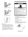
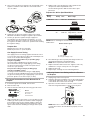
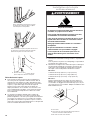
Remove Kick Plate
1. Your range will have the kick plate packaged on top of the
unit.
a. Remove kick plate from top of range and grate pack.
b. Lay kick plate to the side to avoid scratching.
2. For 48" (121.9 cm) models only, rotate center support
counterclockwise off the pallet until it stops.
NOTE: This support is used only for shipping and is not
needed for installation.
3. Lay a piece of cardboard from packaging on the oor behind
range. Using two or more people, rmly grasp each side of
range. Lift range up about 3" (8.0 cm) and move it back until
range is off shipping pallet. Set range oncardboard to avoid
damaging oor.
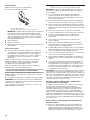
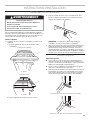
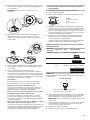
Remove Door
Door Removal
■ Do not remove the side door spacers until the range is ready
to install. Removing the door spacers could allow the door to
shift, damaging the door latch.
■ Do not lift or move the range by the door handle(s) or control
panel.
■ Prior to installing the range, you will need to remove the oven
door(s). Prepare a surface where you will place the door(s).
This surface should be at and covered with a soft blanket,
or use the corner posts from the packaging material.
WARNING
Excessive Weight Hazard
Use two or more people to move and install range.
Failure to do so can result in back or other injury.
In packaging
A. Kick plate
A
Packaging removed
A. Kick plate
A
B
A
A. Oven door hinge in the locked position
B. Oven door hinge in the unlocked position

10
Replace the Door
■ To replace the oven door(s), locate the slots in the oven
cavity for the hinge locks and repeat the steps above in
reverse order. Make sure the door closes properly and there
is no interference from the door latch. If necessary, remove
the door and repeat the steps above. If power is connected
to the range, open and close the door to make sure the oven
light comes on and goes off appropriately.
■ The range is equipped with leveling legs and rollers. Once
the range is removed from the shipping pallet, make sure the
leveling legs are not touching the oor and use the rollers
to move the range into position. Always cover the ooring
surface to avoid damage to the oor. Do not roll the range
directly on the oor.
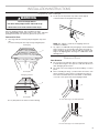
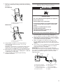
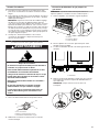
Install Anti-Tip Bracket
1. Determine which mounting method to use: oor or wall.
If you have a stone or masonry oor, you can use the
wallmounting method.
2. Determine and mark centerline of the cutout space. The
mounting bracket must be installed on the left side of the
cutout. Position mounting bracket in cutout as shown in the
following illustration.
Measurement B:
30" (76.2 cm) ranges: 13" (33.0 cm)
36" (91.4 cm) ranges: 16" (40.6 cm)
48" (121.9 cm) ranges: 22" (55.9 cm)
Measurement C:
Optional distance from back wall. If back wall is constructed
of a combustible material and a backguard is not installed, a
6" (15.2 cm) minimum clearance is required for all models.
Install anti-tip bracket accordingly.
Partially close the door to engage the
door latch locks. The door will stop at
this point.
Use two hands to remove and replace
the oven door(s). It may be necessary to
gently shift door from side to side.
A
A. Slot in the oven frame for the
door hinge lock
WARNING
Tip Over Hazard
A child or adult can tip the range and be killed.
Install anti-tip bracket to floor or wall per installation
instructions.
Slide range back so rear range foot is engaged in the
slot of the anti-tip bracket.
Re-engage anti-tip bracket if range is moved.
Do not operate range without anti-tip bracket installed
and engaged.
Failure to follow these instructions can result in death
or serious burns to children and adults.
A
C
B
A. Centerline
B. Centerline of cutout to outside
edge of anti-tip bracket
C. Back wall to back of range

11
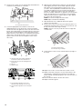
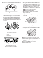
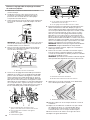
3. Drill two 1/8" (3.0 mm) holes that correspond to the bracket
holes of the determined mounting method. See the following
illustrations.
Floor Mounting
Wall Mounting
4. Using a Phillips screwdriver, mount anti-tip bracket
tothewall or oor with the two #12 x 1
5
⁄
8
" (4.1 cm)
screwsprovided.
Depending on the thickness of your ooring, longer screws
may be necessary to anchor the bracket to the suboor.
Longer screws are available from your local hardware store.
5. Move range close enough to opening to allow for electrical
connections to be made. Remove shipping base, cardboard,
or hardboard from under range.
6. Continue installing your range using the following
installationinstructions.
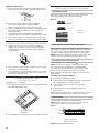
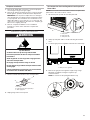
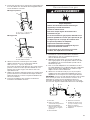
Make Gas Connection
1. Assemble exible connector from gas supply pipe to
pressure regulator located in the middle rear of the range.
2. Apply pipe-joint compound made for use with Propane gas
to the smaller thread ends of the exible connector adapters.
(SeeB and G in the following illustration.)
3. Attach one adapter to the gas pressure regulator and
the other adapter to the gas shut-off valve. Tighten both
adapters, being certain not to move or turn the gas pressure
regulator.
4. Use a 15/16" (2.4 cm) combination wrench and an adjustable
wrench to attach the exible gas supply to the adapters.
Check that connector is not kinked.
IMPORTANT: All connections must be wrench-tightened.
Donotmake connections to the gas regulator too tight. Making
the connections too tight may crack the regulator and cause a
gas leak. Do not allow the regulator to turn or move when
tightening ttings.
B
A
A. #12 x 1
5
⁄
8
" (4.1 cm) screws
B. Anti-tip bracket
B
A
A. #12 x 1
5
⁄
8
" (4.1 cm) screws
B. Anti-tip bracket
WARNING
Explosion Hazard
Use a new CSA International approved gas supply line.
Install a shut-off valve.
Securely tighten all gas connections.
If connected to propane, have a qualified person make
sure gas pressure does not exceed 14" (36 cm) water
column.
Examples of a qualified person include:
licensed heating personnel,
authorized gas company personnel, and
authorized service personnel.
Failure to do so can result in death, explosion, or fire.
A
B
C
D
E
FG
H
A. Gas pressure regulator
B. Use pipe-joint compound.
C. Adapter (must have 1/2"
[1.3 cm] male pipe thread)
D. Flexible connector
E. Manual gas shut-off valve
F. 1/2" (1.3 cm) or
3/4" (1.9 cm) gas pipe
G. Use pipe-joint compound.
H. Adapter

12
Complete Connection
1. Open the manual shut-off valve in the gas supply line. The
valve is open when the handle is parallel to the gas pipe.
2. Test all connections by brushing on an approved
noncorrosive leak-detection solution. If bubbles
appear,aleak is indicated. Correct any leak found.
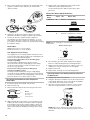
3. Remove range burner caps, and grates from parts package.
Place burner caps on burner bases. Place grates over
burners andcaps.
4. Check that the range is plugged into the appropriate
grounded outlet. (See the “Electrical Requirements” section.)
5. Turn on power supply. For further information, please refer
tothe user instructions located in the Use and Care Guide.
Verify Anti-Tip Bracket Location
1. Using a 5/16" (7.9 mm) socket or wrench, turn all four
leveling rods one full turn to raise the range and provide
enough clearance for the rear leveling leg to slide into the
anti-tip bracket.
2. Move range into its nal location, making sure rear leveling
leg slides into anti-tip bracket.
3. Use a ashlight to look underneath the bottom of the range
and visually check that the rear range foot is inserted into
theslot of the anti-tip bracket.
Install Griddle Tray
(On griddle models)
The griddle is factory installed.
1. Place drip tray in the well at the front of the griddle. Slide tray
toward the back until it stops.
2. Clean griddle before using. Refer to the Use and Care Guide.
Electronic Ignition System
Install Burner Caps
Place burner caps on top of burner. If burner caps are not
properly positioned, surfaceburners will not light.
Burners
Initial Lighting and Gas Flame Adjustments
Range burners use electronic igniters in place of standing
pilots. When the Range Control Knob is turned to any position,
the system creates a spark to light the burner. This sparking
continues until the ame is lit or the knob is turned to OFF.
NOTE: The rst time igniting the burners will take longer. This
allows the gas to reach the burners during the rst use.
Check Operation of Range Burners
Push in and turn each Control Knob to .
NOTE: You will hear a clicking sound while the line clears.
The surface burners and grill ames should light within
4seconds. The rst time a burner is lit, it may take longer
than4seconds to light because of air in the gas line.
After verifying the proper burner operation, turn the Control
Knobs to OFF.
If burners do not light properly:
■ Turn Range Control Knob to OFF.
■ Check that the range is plugged in and the circuit breaker
has not tripped or the fuse has not blown.
■ Check that the gas shut-off valves are set to the
openposition.
■ Check that burner caps are properly positioned on
burnerbases.
Repeat startup. If a burner does not light at this point, contact
your dealer or authorized service company for assistance.
Flame Height
The range ame should be a steady blue ame.
NOTE: Flame heights are factory set. If they don’t appear
correct, please contact your service provider.
Burner
NOTE: Dual Stacked burner shown.
A
B
A. Closed valve
B. Open valve
A
B
A. Griddle drip tray
B. Griddle
A. Incorrect
B. Correct
A. Upper (main) flame
B. Lower (simmer) flame
B
A
A
B
A
B

13
Level Range
NOTE: Range must be level for satisfactory baking performance.
1. Place rack in oven.
2. Place level on rack and check levelness of the range, rst
side to side, then front to back.
3. If range is not level, adjust the leveling rods. Using a wrench,
turn leveling rods located behind the kick plate to level range
and to raise or lower range to the desired countertop height.
NOTE: All roller feet must be off the oor upon nal installation.
NOTE: Turning clockwise raises the unit, whereas turning
counterclockwise lowers the unit.
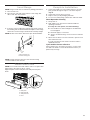
Install Kick Plate
NOTE: Door must be removed in order to remove or replace kick
plate. Refer to the “Remove Door” section.
Align kick plate over the kick plate slots and push kick plate
down.
Complete Installation
1. Check that all parts are now installed. If there is an extra
part, go back through the steps to see which step was
skipped.
2. Check that you have all of your tools.
3. Dispose of/recycle all packaging materials.
4. For oven use and cleaning, read the Use and Care Guide.
Check Operation of Oven(s)
1. Turn power on.
2. Start a Bake cycle. See the Use and Care Guide for
operating instructions.
If oven(s) does not operate, check the following:
■ Household fuse is intact and tight or circuit breaker
hasnot tripped.
■ Electrical supply is connected.
■ See the “Troubleshooting” section in the Use and Care
Guide.
3. When oven has been on for 10–15 minutes, open the oven
door and feel for heat.
If you do not feel heat, turn off the oven and contact a
qualied technician.
If you need Assistance or Service:
Please reference the “Assistance or Service” section of the
Useand Care Guide or contact the dealer from whom you
purchased your range.
A
A
B
B
A. Rear leveling rod
B. Front leveling rod
A
B
D
C
D
A. Kick plate
B. Kick plate tab
C. Kick plate slot
D. Feet

14
GAS CONVERSIONS
IMPORTANT: Gas conversions from Natural gas to Propane gas
must be done by a qualied installer.
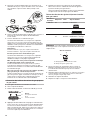
Propane Gas Conversion
1. Turn the manual shut-off valve to the closed position.
2. Unplug range or disconnect power.
To Convert Gas Pressure Regulator from Natural Gas
to Propane
NOTE: Door must be removed in order to remove or replace kick
plate. Refer to the “Remove Door” section.
1. Lift the kick plate up and off of the kick plate tab.
2. Gently lay kick plate aside to avoid scratching.
3. Locate the gas pressure regulator at the left rear of the range.
4. Remove the gas pressure regulator cap by using a
large at-blade screwdriver, turning the regulator cap
counterclockwise.
NOTE: Do not remove the spring beneath the cap.
WARNING
Explosion Hazard
Use a new CSA International approved gas supply line.
Install a shut-off valve.
Securely tighten all gas connections.
If connected to propane, have a qualified person make
sure gas pressure does not exceed 14" (36 cm) water
column.
Examples of a qualified person include:
licensed heating personnel,
authorized gas company personnel, and
authorized service personnel.
Failure to do so can result in death, explosion, or fire.
WARNING
Tip Over Hazard
A child or adult can tip the range and be killed.
Install anti-tip bracket to floor or wall per installation
instructions.
Slide range back so rear range foot is engaged in the
slot of the anti-tip bracket.
Re-engage anti-tip bracket if range is moved.
Do not operate range without anti-tip bracket installed
and engaged.
Failure to follow these instructions can result in death
or serious burns to children and adults.
A. To range
B. Shut-off valve (closed position)
C. Gas supply line
A
B
C
A
B
C
A. Kick plate
B. Kick plate tab
C. Kick plate slot
A
A. Gas pressure regulator

15
5. Turn over the gas pressure regulator cap, and reinstall on the
regulator so that the hollow end faces out and the letters
“LP” are visible.
6. Tighten the gas pressure regulator cap by using a large
at-blade screwdriver, turning the regulator cap clockwise.
7. Test the gas pressure regulator and gas supply line.
The regulator must be checked at a minimum 1" (2.5 cm)
water column above the set pressure. The inlet pressure to
the regulator should be as follows for operation and checking
the regulator setting:
Propane Gas:
Minimum pressure: 10" (25.4 cm) WCP
Maximum pressure: 14" (35.6 cm) WCP
Gas Supply Pressure Testing
Gas supply pressure for testing regulator must be at least 1"
(2.5 cm) water column pressure above the manifold pressure
shown on the model/serial/rating plate.
Line pressure testing above 1/2 psi (3.5 kPa) gauge
(14" [35.6cm] WCP)
The range and its individual shut-off valve must be
disconnected from the gas supply piping system during
anypressure testing of that system at test pressures in
excess of 1/2 psi (3.5 kPa).
Line pressure testing at 1/2 psi (3.5 kPa) gauge
(14" [35.6cm]WCP) orlower
The range must be isolated from the gas supply piping
system by closing its individual manual shut-off valve during
any pressure testing of the gas supply piping system at test
pressures equal to or less than 1/2 psi (3.5 kPa).
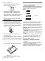
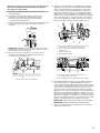
To Convert Surface Burners from Natural Gas to
Propane
1. If the burner grates are installed, remove them.
2. Remove burner cap.
3. Remove the burner base by rst removing (2) T-20 screws.
Burner
A. Burner cap
B. Screws
C. Burner base
4. Apply masking tape to the end of a 7 mm nut driver to help
hold the gas orice spud in the nut driver while changing it.
Insert nut driver into the gas opening and press down onto
the gas orice spud and remove by turning the gas orice
spud counterclockwise and lifting out. Set gas orice spud
aside.
5. Replace with correct Propane gas orice spud. See the
“Propane Gas Orice Spud/Hood Chart”.
Use the following chart to nd the exact orice spud
placement.
Propane Gas Orifice Spud/Hood Chart
Burner
Rating
Stamp Size Burner Style
4,000 BTUs 63 0.63 mm Small burner
12,000 BTUs 99 0.99 mm Medium burner
12,000 BTUs 95
50
0.95 mm
0.50 mm
Large burner – main
Larger burner – simmer
NOTE: Refer to serial tag for more information on burner ratings
and locations.
Burner orice spud
6. Place Natural gas orice in plastic parts bag for future use
and keep with package containing literature.
NOTE: There may be extra orices in your kit.
7. Replace the burner base and screws. Tighten screws only
until burner is snug to cooktop, do not over-tighten.
8. Replace burner cap.
9. Repeat steps 2 through 8 for the remaining burners.
Adjusting Simmer Low Setting on Surface Burners
for Propane
1. Unplug range or disconnect power.
2. Using the square bit screwdriver, remove the surface burner
control knobs and bezels (Oven control knobs and griddle
control knobs do not have to be removed).
3. Open the oven door and remove the two screws on each
side of the range that hold the control console in place.
NOTE: Make sure to leave the door open or the control
console will not rest in the side brackets properly once it is
attached.
A
B
A. Size stamp
B. Fuel type stamp (L or N)
A
C
B

16
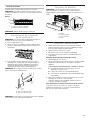
4. Pull up on the control console and let it drop forward into the
notched console brackets on each side.
5. Locate the appropriate low-turndown screw for the
appropriate burner on the given valve. The low-turndown
screw for the left rear, right rear, center rear, and center front
burner valves (aluminum) is located through the center of the
valve stem. The low-turndown screw for the left front and
right front burner valves (brass) is located behind the ignition
switch on the valve body, left of the stem. To remove the
ignition switch cut the wire tie and pull the switch off the
valve stem.
6. With the burner ON (the burner will have to be lit manually
with a lighter), and set to simmer LOW, adjust the simmer
ame down to the proper BTU level. Using a 1/8" x 4¼"
(3.2mm x 10.8 cm) at blade screwdriver, turn the simmer
low-turndown adjustment screw clockwise until the ame
height is at, or below, the bottom of the cap. If the ame
becomes unstable and ickers or appears to race around the
burner, the adjustment is too low and the screw should be
adjusted counterclockwise until the ame is stable. Repeat
this step for all surface burners.
NOTE: Use a knob to adjust the burner valve.
NOTE: Adjust each burner individually.
7. After adjustments are completed, replace the ignition
switches onto the valves.
8. Lift up on the control console and set it back into place. For
a proper t, the ange of the control console must hook over
the lip on the front of the range cooktop.
NOTE: It may be necessary to lift valve stems to align with
console holes.
9. Check that the control console is ush with the top edge of
the range.
10. Replace the screws on each side of the control console.
11. Replace the bezels using the 2 screws which attach to the
valve brackets, making note that there are front and rear
bezels and will only attach properly in the correct location on
the console.
12. Push the Surface Knobs onto the valve stems.
13. Replace the burner grates.
A
A. Control console bracket
DC
B
A
A. Aluminum Valve for Left Rear, Right Rear,
Center Rear, and Center Front burners
B. Brass Valve for Left Front and Right Front
Dual burners
C. Wire Tie
D. Ignition switch
A. Control console flange
B. Front lip of range cooktop
A
B
A. Flush with range top
A
A. Low-turndown adjustment screw for
Aluminum Valve through center of stem
B. Low-turndown adjustment screw for Brass
Valve
BA

17
Complete Installation
1. Refer to the “Make Gas Connection” section for properly
connecting the range to the gas supply.
2. Refer to the “Electronic Ignition System” section for proper
burner ignition, operation, and burner ame adjustments.
IMPORTANT: You may have to adjust the “LO” setting for
each range burner. Checking for proper range burner ame
is very important. The small inner cone should have a very
distinct blue ame 1/4" (6.4 mm) to 1/2" (1.3 cm) long. The
outer cone is not as distinct as the inner cone. Propane gas
ames have a slightly yellow tip.
3. Refer to “Complete Installation” in the “Installation
Instructions” section of this manual to complete this
procedure.
Natural Gas Conversion
1. Turn the manual shut-off valve to the closed position.
2. Unplug range or disconnect power.
To Convert Gas Pressure Regulator from Propane to
Natural Gas
NOTE: Door must be removed in order to remove or replace kick
plate. Refer to the “Remove Door” section.
1. Lift the kick plate up and off of the kick plate tab.
2. Gently lay kick plate aside to avoid scratching the stainless
steel.
3. Locate the gas pressure regulator at the left rear of the range.
4. Remove the gas pressure regulator cap by using a large
at-blade screwdriver, turning the regulator cap
counterclockwise.
NOTE: Do not remove the spring beneath the cap.
WARNING
Tip Over Hazard
A child or adult can tip the range and be killed.
Install anti-tip bracket to floor or wall per installation
instructions.
Slide range back so rear range foot is engaged in the
slot of the anti-tip bracket.
Re-engage anti-tip bracket if range is moved.
Do not operate range without anti-tip bracket installed
and engaged.
Failure to follow these instructions can result in death
or serious burns to children and adults.
A
B
C
A. To range
B. Shut-off valve (closed position)
C. Gas supply line
A
B
C
A. Kick plate
B. Kick plate tab
C. Kick plate slot
A
A. Gas pressure regulator

18
5. Turn over the gas pressure regulator cap, and reinstall on the
regulator so that the hollow end faces in and the letters
“NAT” are visible.
6. Tighten the gas pressure regulator cap by using a large
at-blade screwdriver, turning the regulator cap clockwise.
7. Test the gas pressure regulator and gas supply line.
The regulator must be checked at a minimum 1" (2.5 cm)
water column above the set pressure. The inlet pressure to
the regulator should be as follows for operation and checking
the regulator setting:
Natural Gas:
Minimum pressure: 5" (12.7 cm) WCP
Maximum pressure: 14" (35.6 cm) WCP
Gas Supply Pressure Testing
Gas supply pressure for testing regulator must be at least 1"
(2.5 cm) water column pressure above the manifold pressure
shown on the model/serial/rating plate.
Line pressure testing above 1/2 psi (3.5 kPa) gauge
(14" [35.6cm] WCP)
The range and its individual shut-off valve must be
disconnected from the gas supply piping system during
anypressure testing of that system at test pressures in
excess of 1/2 psi (3.5 kPa).
Line pressure testing at 1/2 psi (3.5 kPa) gauge
(14" [35.6cm]WCP) orlower
The range must be isolated from the gas supply piping
system by closing its individual manual shut-off valve during
any pressure testing of the gas supply piping system at test
pressures equal to or less than 1/2 psi (3.5 kPa)
To Convert Surface Burners from Propane to
Natural Gas
1. If the burner grates are installed, remove them.
2. Remove burner cap.
3. Remove the burner base by rst removing (2) T-20 screws.
Burner
A. Burner cap
B. Screws
C. Burner base
4. Apply masking tape to the end of a 7 mm nut driver to help
hold the gas orice spud in the nut driver while changing it.
Insert nut driver into the gas opening and press down onto
the gas orice spud and remove by turning the gas orice
spud counterclockwise and lifting out. Set gas orice spud
aside.
5. Replace with correct Natural gas orice spud. See the
“Natural Gas Orice Spud/Hood Chart.”
Use the following chart to nd the exact orice spud
placement.
Natural Gas Orifice Spud/Hood Chart
Burner
Rating
Stamp Size Burner Style
5,000 BTUs 99 0.99 mm Small burner
15,000 BTUs 175 1.75 mm Medium burner
20,000 BTUs 203
78
2.03 mm
0.78 mm
Large burner – main
Large burner – simmer
NOTE: Refer to serial tag for more information on burner ratings
and locations.
Burner orice spud
6. Place Propane gas orice spuds in plastic parts bag for
future use and keep with package containing literature.
7. Replace the burner base and screws. Tighten screws only
until burner is snug to cooktop, do not over-tighten.
8. Replace burner cap.
9. Repeat steps 2 through 8 for the remaining burners.
Adjusting Simmer Low Setting on Surface Burners
for Natural Gas
1. Unplug range or disconnect power.
2. Using the square bit screwdriver, remove the surface burner
control knobs and bezels (Oven control knobs and griddle
control knobs do not have to be removed).
3. Open the oven door and remove the two screws on each
side of the range that hold the control console in place.
NOTE: Make sure to leave the door open or the control
console will not rest in the side brackets properly once it is
attached.
A
C
B
A
B
A. Size stamp
B. Fuel type stamp (L or N)

19
4. Pull up on the control console and let it drop forward into the
notched console brackets on each side.
5. Locate the appropriate low-turndown screw for the
appropriate burner on the given valve. The low-turndown
screw for the left rear, right rear, center rear, and center front
burner valves (aluminum) is located through the center of
the valve stem. The low-turndown screw for the left front
and right front burner valves (brass) is located behind the
ignition switch on the valve body, left of the stem. To remove
the ignition switch cut the wire tie and pull the switch off the
valve stem.
6. With the burner ON (the burner will have to be lit manually
with a lighter), and set to simmer LOW, adjust the simmer
ame up to the proper BTU level. Using a 1/8" x 4¼"
(3.2mm x 10.8 cm) at blade screwdriver, turn the simmer
low-turndown adjustment screw counterclockwise until the
ame height is at, or below, the bottom of the cap. If the
ame becomes unstable and ickers or appears to race
around the burner, the adjustment is too low and the screw
should be adjusted counterclockwise until the ame is
stable. Repeat this step for all surface burners.
NOTE: Use a knob to adjust the burner valve.
NOTE: Adjust each burner individually.
7. After adjustments are completed, replace the ignition
switches onto the valves.
8. Lift up on the control console and set it back into place. For
a proper t, the ange of the control console must hook over
the lip on the front of the range cooktop.
NOTE: It may be necessary to lift valve stems to align with
console holes.
9. Check that the control console is ush with the top edge of
the range.
10. Replace the screws on each side of the control console.
11. Replace the bezels using the 2 screws which attach to the
valve brackets, making note that there are front and rear
bezels and will only attach properly in the correct location on
the console.
12. Push the Surface Knobs onto the valve stems.
13. Replace the burner grates.
A
A. Control console bracket
A. Control console flange
B. Front lip of range cooktop
A
B
A. Flush with range top
A
A. Aluminum Valve for Left Rear, Right Rear,
Center Rear, and Center Front burners
B. Brass Valve for Left Front and Right Front
Dual burners
C. Wire Tie
D. Ignition switch
DC
B
A
BA
A. Low-turndown adjustment screw for
Aluminum Valve through center of stem
B. Low-turndown adjustment screw for Brass
Valve

20
Complete Installation
1. Refer to the “Make Gas Connection” section for properly connecting the range to the gas supply.
2. Refer to the “Electronic Ignition System” section for proper burner ignition, operation, and burner ame adjustments.
IMPORTANT: You may have to adjust the “LO” setting for each range burner.
Checking for proper range burner ame is very important. The small inner cone should have a very distinct blue ame
1/4"(6.4mm) to 1/2" (1.3 cm) long. The outer cone is not as distinct as the inner cone. Propane gas ames have a slightly yellow
tip.
3. Refer to “Complete Installation” in the “Installation Instructions” section of this manual to complete this procedure.
Page is loading ...
Page is loading ...
Page is loading ...
Page is loading ...
Page is loading ...
Page is loading ...
Page is loading ...
Page is loading ...
Page is loading ...
Page is loading ...
Page is loading ...
Page is loading ...
Page is loading ...
Page is loading ...
Page is loading ...
Page is loading ...
Page is loading ...
Page is loading ...
Page is loading ...
Page is loading ...
-
 1
1
-
 2
2
-
 3
3
-
 4
4
-
 5
5
-
 6
6
-
 7
7
-
 8
8
-
 9
9
-
 10
10
-
 11
11
-
 12
12
-
 13
13
-
 14
14
-
 15
15
-
 16
16
-
 17
17
-
 18
18
-
 19
19
-
 20
20
-
 21
21
-
 22
22
-
 23
23
-
 24
24
-
 25
25
-
 26
26
-
 27
27
-
 28
28
-
 29
29
-
 30
30
-
 31
31
-
 32
32
-
 33
33
-
 34
34
-
 35
35
-
 36
36
-
 37
37
-
 38
38
-
 39
39
-
 40
40


KitchenAid KFGC500JAV Installation guide
- Category
- Cookers
- Type
- Installation guide
Ask a question and I''ll find the answer in the document
Finding information in a document is now easier with AI
in other languages
Related papers
-
KitchenAid KDRS407VBU01 Installation guide
-
KitchenAid KFGC558JIB Installation guide
-
KitchenAid KFDC500JPA User manual
-
KitchenAid KDRS483VSS Operating instructions
-
KitchenAid KDRS467VBU Installation guide
-
-
-
KitchenAid KDRU763VSS Installation guide
-
-
KitchenAid KCGC558JSS Installation guide
Other documents
-
JennAir JDRP536HM Installation guide
-
Dacor JGRP430HL Installation guide
-
-
CONTINENTAL EDISON CECM6065S User manual
-
Jenn-Air JGRP548HL00 Installation guide
-
-
Jenn-Air PRO-STYLE JGRP430 User manual
-
-
Whirlpool WFG320M0MS User manual
-
Whirlpool WFG505M0MB User manual