OM-826 Page 5
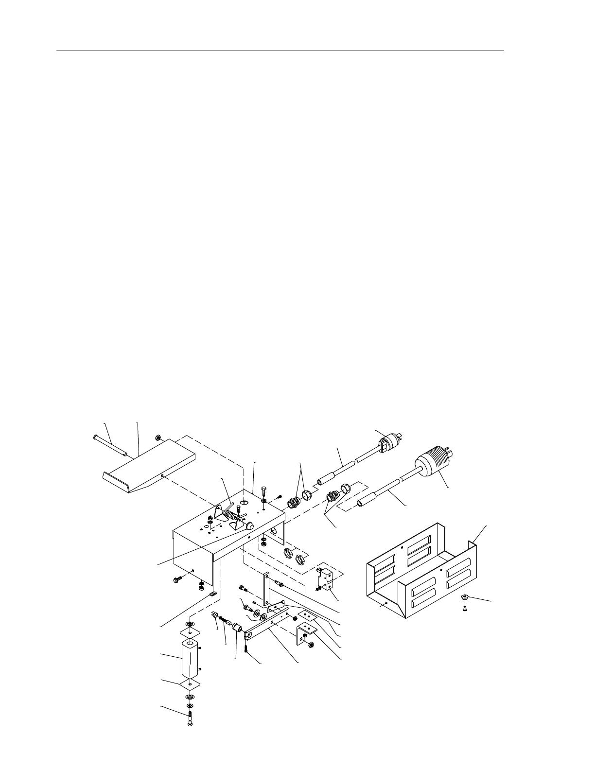
8. Parts List
DescriptionPart No.
Item No.
1 206075 PIN, hinge 1.. .. .. .........................................................
2 019662 PEDAL, foot 1.. .. .. .......................................................
3 175972 SPRING, torsion 1.. .. .. ...................................................
4 +159894 CASE SECTION, cover/end 1.. . .. .........................................
085220 LABEL, caution electric circuit etc 1....... .. .....................................
6 600340 CABLE, port no 16 2/C TYPE SOOW RB JKT 20 Ft.. .. .. .......................
7 039618 PLUG, twlk 2P 2W 20A 250V 1.. .. .. ........................................
8 605797 PLUG, twlk 3P3W 20A 125V 1.. .. .. .........................................
9 204213 CABLE, port no 16 3/C TYPE ST PVC JKT 20 Ft.. .. .. ..........................
10 139042 BUSHING, strain relief .270/.470 ID X .804 mtg hole 2.. . .. ....................
11 014920 CASE SECTION, base/side 1.. . .. ..........................................
12 239388 BUMPER, rbr .875 OD X .188 ID X .39 high recessed 4.. . .. ...................
13 011628 SWITCH, limit 15A 125V 1.. . .. ............................................
14 159897 SCREW, shld stl sch .250-20 x .437 2.. . .. ...................................
15 159895 BAR, pedal control foot 1.. . .. ..............................................
16 010795 ACTUATOR, switch limit 1.. . .. .............................................
17 184179 SPACER, support arm brush 1.. . .. .........................................
18 159892 BRACKET, support arm 1.. . .. .............................................
19 159893 ARM, brush holder 1.. . .. ..................................................
20 604432 SCREW, cap stl sch 8-32 x 1.000 1.. . .. .....................................
21 018639 HOLDER, brush 1.. . .. ....................................................
22 *018640 BRUSH, contact 1.. .. ....................................................
23 161306 CAP, brush holder 1.. . .. ..................................................
24 079625 WASHER, spring stl .500 shakeproof 1.. . .. ..................................
25 159896 SCREW, shld stl sch .312-18 x .375 1.. . .. ...................................
26 601795 BOLT, mach stl hexhd .250-20 x 4.500 1.. . .. ................................
27 276279 INSULATOR, resistor 2.. . .. ...............................................
28 175266 RESISTOR, WW adj 130W 15 ohm 1.. . .. ...................................
29 601855 NUT, weld .250-20 1.. . .. ..................................................
30 010322 NUT, 375-00 slip-on plastic acorn 1.. . .. .....................................
NAMEPLATE (order by model number) 1................. ................................
+ When ordering a component originally displaying a precautionary label, the label should also be ordered.
*Recommended Spare Parts.
To maintain the factory original performance of your equipment, use only Manufacturer’s Suggested
Replacement Parts. Model and serial number required when ordering parts from your local distributor.
Ref 145 917-G
3
4
6
7
8
9
10
11
12
13
14
15
16
17
18
19
20
21
22
23
24
25
26
27
28
29
30
10


