
G3750
Street barriers
EN
English
FA01237-EN
INSTALLATION MANUAL

CAME
Page 2 - Manual FA01237-EN - 07/2018 - © CAME S.p.A. - The contents of this manual may change, at any time, and without notice.
-
Original instructions
Premise
• This producT should only be used for The purpose for which iT was
expliciTly designed. any oTher use is dangerous. caMe s.p.a. is noT liable
for any daMage caused by iMproper, wrongful and unreasonable use. •
The safeTy of This producT and iTs proper fiTTing depends, Therefore, on
respecTing iTs Technical characTerisTics and proper fiTTing, To be done in
sTaTe-of-The-arT fashion, and under safe condiTions as expressly explained
in The liTeraTure ThaT coMes wiTh The producT. • Keep These precauTions
TogeTher wiTh The insTallaTion and operaTion Manuals ThaT coMe wiTh The
operaTor.
Before installing
(checKing whaT's There: if soMeThing is Missing, do noT conTinue unTil you
have coMplied wiTh all safeTy provisions)
• fiTTing and TesTing MusT only be perforMed by qualified Technicians.
laying The cables, insTallaTion and TesTing MusT follow sTaTe-of-The-arT
procedures as dicTaTed by regulaTions • before beginning any operaTion
iT is MandaTory To carefully read all insTrucTion; iMproper insTallaTion
May resulT in serious harM To people and Things. • MaKe sure The booM
is in good Mechanical sTaTe, balanced and aligned, and ThaT iT opens and
closes properly. also, if needed, fiT suiTable proTecTions or use proper
safeTy sensors • if The operaTor is To be insTalled aT a heighT of over
2.5 M froM The ground or oTher access level, MaKe sure you have any
necessary proTecTions and/or warnings in place • MaKe sure ThaT The
opening auToMaTic barrier does noT consTiTuTe a hazard • do noT insTall
The operaTor upside down or onTo eleMenTs ThaT could yield and bend. if
necessary, add suiTable reinforceMenTs To The anchoring poinTs • do noT
insTall on TilTed surfaces • MaKe sure The TeMperaTure range shown on
The producT liTeraTure is suiTable To The cliMaTe where iT will be insTalled
as explained in The Manual. • do noT insTall on TilTed, sloped or uneven
surfaces • MaKe sure any sprinKler sysTeMs cannoT weT The operaTor froM
The ground up.
installation
• suiTably secTion off and deMarcaTe The enTire insTallaTion siTe To prevenT
unauThorized persons froM enTering The area, especially Minors and
children • be careful when handling operaTors ThaT weigh over 20 Kg.
if need be, use proper safeTy hoisTing equipMenT • The ce-MarKed safeTy
devices (phoTocells, sTepping plaTes, sensiTive safeTy-edges, eMergency
buTTons, and so on), MusT be fiTTed in coMpliance wiTh The regulaTions in
effecT and according To sTaTe-of-The-arT criTeria, TaKing inTo accounT The
environMenT, The Type of required service and of The worKing forces applied
To Moving barriers. any shearing or conveying poinTs MusT be sensor-
proTecTed • any residual risKs MusT be clearly shown • all opening
coMMands (ThaT is, buTTons, Key swiTches, MagneTic readers, and so on)
MusT be insTalled aT leasT 1.85 M froM The periMeTer of The barrier's
worKing area, or where They cannoT be reached froM ouTside The barrier.
also, any direcT coMMands (buTTons, Touch panels, and so on) MusT be
insTalled aT leasT 1.5 M froM The ground and MusT noT be reachable
by unauThorized persons • The auToMaTic barrier MusT visibly show iTs
idenTificaTion daTa. • before connecTing The Main power supply MaKe sure
ThaT The idenTificaTion daTa correspond To The Those of The neTworK • The
auToMaTic barrier MusT be connecTed To an effecTive regulaTion grounding
sysTeM.
• The ManufacTurer declines any liabiliTy for using non-original producTs;
which would resulT in warranTy loss • all MainTained acTion coMMands,
MusT be fiTTed in places froM which The Moving barrier and TransiT and
driving areas are visible • apply, if Missing, a perManenT sign showing The
posiTion of The release device • before delivering To The users, MaKe sure
The sysTeM is en 12453 and en 12445 sTandard coMplianT (regarding
iMpacT forces), and also MaKe sure The sysTeM has been properly adjusTed
and ThaT any safeTy, proTecTion and Manual release devices are worKing
properly • apply warning signs where necessary and in a visible place
(such as The gaTe's license plaTe).
sPecial user-instructions and recommendations
• Keep barrier operaTion areas clean and free of any obsTrucTions. MaKe
sure The phoTocell's operaTing field is clear of any obsTrucTions • do noT
allow children To play wiTh fixed coMMands, or To loiTer in The barrier's
Manoeuvring area. Keep any reMoTe conTrol TransMiTTers or any oTher
coMMand device away froM children, To prevenT The operaTor froM being
accidenTally acTivaTed • The apparaTus May be used by children of eighT
years and above and by physically, MenTally and sensory-challenged
people, or even ones wiThouT any experience, provided This happens under
close supervision or once They have been properly insTrucTed To use The
apparaTus safely and To The poTenTial hazards involved. children MusT
noT play wiTh The apparaTus. cleaning and MainTenance by users MusT noT
be done by children, unless properly supervised • frequenTly checK The
sysTeM for any MalfuncTions or signs of wear and Tear or daMage To The
Moving sTrucTures, To The coMponenT parTs, all anchoring poinTs, including
cables and any accessible connecTions. Keep any hinges, Moving joinTs
and booM flange clean, fricTion free and properly lubricaTed. • perforM
funcTional checKs on The phoTocells and every six MonThs. consTanTly
clean The phoTocells' glass covers using a slighTly waTer-MoisTened cloTh;
do noT use solvenTs or cheMicals ThaT could daMage The devices • if
repairs or ModificaTions are required To The sysTeM, release The operaTor
and do noT use iT unTil safeTy condiTions have been resTored • cuT off
The power supply before releasing The operaTor for Manual openings and
before any oTher operaTion, To prevenT poTenTially hazardous siTuaTions.
read The insTrucTions • if The power supply cable is daMaged, iT MusT be
replaced by The ManufacTurer or auThorized Technical assisTance service,
or in any case, by siMilarly qualified persons, To prevenT any risK • iT is
forbidden for users To perforM any operaTions ThaT are noT
expressly required of TheM and which are noT lisTed
in The Manuals. for any repairs, ModificaTions and adjusTMenTs and for
exTra-ordinary MainTenance, call Technical assisTance • log The
job and checKs inTo The periodic MainTenance log.
further recommendations for all
• Keep away froM and do noT loiTer near The barrier and Mechanical
Moving parTs • do noT enTer The barrier's area of operaTion when iT is
Moving • do noT counTer The operaTor's MoveMenT as This could resulT
in dangerous siTuaTions • always pay special aTTenTion To any dangerous
poinTs, which have To be labelled wiTh specific picTograMs and/or blacK and
yellow sTripes • when using a selecTor swiTch or a coMMand in MainTained
acTions, Keep checKing ThaT There are no persons wiThin The operaTing range
of any Moving parTs, unTil The coMMand is released • The barrier May Move
aT any TiMe and wiThouT warning • always cuT off The power supply before
perforMing any MainTenance or cleaning.
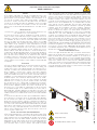
WARNING!
important safety instructions for people:
READ CAREFULLY!
Danger of hand crushing
Danger! High voltage.
No transiting while the barrier is moving

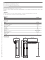
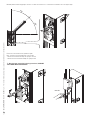
338
1007
260 max. 3750
884
265220
Page 3 - Manual FA01237-EN - 07/2018 - © CAME S.p.A. - The contents of this manual may change, at any time, and without notice.
-
Original instructions
This symbol shows the parts which must be read with care.
⚠ This symbol shows the parts which describe safety issues.
☞ This symbol indicates what should be communicated to users.
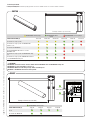
KEY
DESCRIPTION
Barrier made of varnished galvanized steel set up to fit accessories.
REQUEST EITHER LEFT OR RIGHT-HAND BARRIERS WHEN ORDERING. THE ILLUSTRATIONS IN THIS MANUAL ARE ALL FOR LEFT-HAND
BARRIERS!
Intended use
The barrier is designed for use in private and public parking facilities, in residential settings and for high-rates of vehicle trac.
Any installation and use other than that specified in this manual is forbidden.
Limits to use
Model G3750
Maximum clearance width of the passage (m) 3.75
Technical data
Model G3750
Protection rating (IP) 54
Power supply (V - 50/60 Hz) 230 AC
Motor power supply (V) 24 DC
Max draw (A) 15
Power (W) 300
Torque (Nm) 200
Opening time (s) 2 to 6
Duty cycle INTENSIVE SERVICE
Operating temperature (°C) -20 to +55
Reduction ration (i) 1/202
Apparatus class I
Weight (Kg) 47
Dimensions (mm)

CAME
1
5
11
7
9
4
3
12
10
8
6
2
6
1
7
8
9
10
6
2
3
4 5
Page 4 - Manual FA01237-EN - 07/2018 - © CAME S.p.A. - The contents of this manual may change, at any time, and without notice.
-
Original instructions
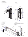
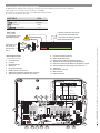
Description of parts
1. Cabinet
2. Transmission-shaft plate
3. Boom-attachment cover
4. Anti-shearing protective cover
5. Gearmotor release with customized key
6. Hatch lock with customized key
7. Gearmotor
8. Control panel
9. Balancing spring
10. Inspection hatch
Standard installation
1. Barrier
2. Flashing light
3. Semi-oval boom
4. Luminous cord
5. Red reflective strips
6. Photocells
7. Photocell casing
8. Photocells post
9. Fixed rest
10. Control device (keypad, magnetic key, transponder, etc.)
11. Control device post
12. Magnetic coils

Page 5 - Manual FA01237-EN - 07/2018 - © CAME S.p.A. - The contents of this manual may change, at any time, and without notice.
-
Original instructions
GENERAL INSTRUCTIONS FOR INSTALLING
⚠Installation must be carried out by expert qualified personnel and in full compliance with the regulations in force.
Important! Using original CAME control and safety devices and accessories ensures easy installation and system maintenance.
Preliminary checks
⚠ Before beginning, do the following::
• make sure the plate is anchored to a solid spot;
• make sure you have set up a suitable dual pole cut off device along the power supply that is compliant with the installation rules. It should
completely cut off the power supply according to category III surcharge conditions (that is, with minimum contact openings of 3 mm);
• make sure that any connections inside the case (that provide continuance to the protective circuit) are fitted with extra insulation as compared
to the other conductive parts inside;
• set up suitable tubes and conduits for the electric cables to pass through, making sure they are protected from any mechanical damage.
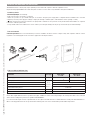
Tools and materials
Make sure you have all the tools and materials you need for installation at hand to work in complete safety and compliance with the current
regulations. The following figure shows some basic equipment needed by the installer.
Connection Cable type Cable length
1 < 15 m
Cable length
15 < 30 m
Power supply 230 V AC H05RN-F 3G x 1.5 mm23G x 2.5 mm2
Flashing light FROR CEI
20-22
CEI EN
50267-2-1
2 x 0,5 mm2-
Photocell transmitters 2 x 0,5 mm2
Photocell receivers 4 x 0,5 mm2
Command and safety device 2 x 0,5 mm2
Antenna RG58 max 10 m
Metal mass detector (see product literature)
If cable lengths differ from those specified in the table, establish the cable sections depending on the actual power draw of the connected
devices and according to the provisions of regulation CEI EN 60204-1.
For connections that require several, sequential loads, the sizes given in the table must be re-evaluated based on actual power draw and distances.
When connecting products that are not specified in this manual, please refer to the documentation provided with said products.
Types of cable and minimum sizes

350
400
200
r 40
Page 6 - Manual FA01237-EN - 07/2018 - © CAME S.p.A. - The contents of this manual may change, at any time, and without notice.
-
Original instructions
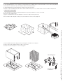
M12 UNI5588 nut
M12x40 UNI
5739 screw
Washer
Set up a foundation frame that is larger than the anchoring plate and sink it into the dug hole.
Fit an iron cage into the foundation frame to reinforce the concrete.
Assemble the four anchoring braces to the anchoring plate.
INSTALLATION
⚠ The following illustrations are mere examples. Consider that the space available where to fit the barrier and accessories will vary depending on
the area where it is installed. It is up to the installer to find the most suitable solution.
⚠ Caution! Warning! Use hoisting equipment to transport and position the barrier.
During the set up and installing stages the barrier could be unstable and tip over. So, be careful and do not lean on it until it is fully fastened.
Preparing the fastening plate
⚠ If the flooring does not allow for a sturdy fastening of the entry unit, you will have to set up a cement slab.
Dig a hole for the foundation frame.
Set up the corrugated tubes needed for making the connections coming out of the junction pit.
The number of tubes depends on the type of system and the accessories you are going to fit.

1
2
Page 7 - Manual FA01237-EN - 07/2018 - © CAME S.p.A. - The contents of this manual may change, at any time, and without notice.
-
Original instructions
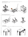
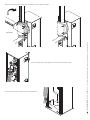
Fill the hole with earth around the concrete block.
Remove the nut and washer from the bolts.
Fit the electric cables into the tubes so that they come out about 600 mm.
Place the plate over the iron cage.
Fill the foundation frame with concrete. The base must be perfectly level with the bolts which are entirely above surface.
Wait at least 24 hrs for the concrete to solidify.
Remove the foundation frame.
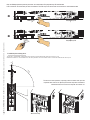
Fastening the barrier
Fit the customized key into the lock and turn it counter-clockwise . Remove the inspection hatch from the cabinet .

230 mm
30 mm
UNI 5931 M8x12
Page 8 - Manual FA01237-EN - 07/2018 - © CAME S.p.A. - The contents of this manual may change, at any time, and without notice.
-
Original instructions
M12 UNI 5588 nut
Washer
To change the rotation at a later date, request the documentation from your local retailer or contact Came in your Country (see the
last page or visit www.came.com)
LEFT barrier RIGHT barrier
Entry side
Internal zone
Entry side
Internal zone
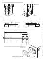
The cabinet should be installed with the inspection hatch on the most accessible side to make any adjusting easier.
Place the cabinet onto the anchoring plate and fasten it using nuts and washers.
Measure the length of the boom and shock-resistant frame by measuring the length of the passage width. Cut o any excess.
Boom length
Shock-proof frame length
Passage width (3750 mm max.)
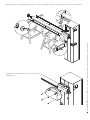
Place the boom-attachment cover against the transmission shaft plate; use only one
screw and leave it loose.

UNI 7687
M3x8
Page 9 - Manual FA01237-EN - 07/2018 - © CAME S.p.A. - The contents of this manual may change, at any time, and without notice.
-
Original instructions
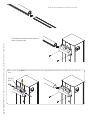
Fit the shock-resistant frame to the boom's lower side.
Fit the boom into the boom-attaching cover and
fasten it using the screws.
Note: to mount with the G0402 boom, fit and fasten the two spacers (supplied with the boom) in the boom attachment, as shown in the
figure.

Page 10 - Manual FA01237-EN - 07/2018 - © CAME S.p.A. - The contents of this manual may change, at any time, and without notice.
-
Original instructions
Cut the groove profiles to length and fit them into the boom's groove. Perform this procedure on both ends. Fit the cap onto the end of the boom.
Fit and fasten the anti-shearing protective cover onto the boom
attachment-cover.

G0402
B1
B2
G03750
Page 11 - Manual FA01237-EN - 07/2018 - © CAME S.p.A. - The contents of this manual may change, at any time, and without notice.
-
Original instructions
Passage clearance (3.75 m max.)
Fitting the springs
⚠ WARNING!
001G02802 Cannot be used on barriers fitted with the 001G0465 skirt or 001G02808 swing rest
001G02808 For passage widths of up to 3 m.
001G02807 MUST be used with passage widths exceeding 3 m.
001G0465 - 001G02808 Cannot be used together.
The boom includes the transparent groove cover and end cap.
A
001G02040 Ø 40 mm springs
B
001G04060 Ø 50 mm
springs
C 001G06080 Ø 55 mm springs
BOOM COMPOSITION (m)
1.5 to 1.75 1.75 to 2.25 2.25 to 2.75 2.75 to 3.25 3.25 to 3.5 3.5 to 3.75
Boom with shock-proof profile
A A A B B C
Boom with shock-proof profile and 001G028401
luminous cord
A A B B B C
Boom with skirt 001G0465
A B B C C
Boom with 001G028401 luminous cord and
001G0465 skirt
A B B C C
Boom with shock-proof profile and 001G02808 swing
rest
A B B C
Boom with shock-proof profile, 001G028401 luminous
cord and 001G02808 swing rest
A B B C
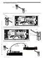
Balancing the boom
Before proceeding, check that the spring you have chosen is suitable for the accessories and the clearance.
Passage clearance (3.75 m max.)
B
001G04060 Ø 50 mm springs
BOOM COMPOSITION (m)
1.5 to 2.0 2.0 to 2.5 2.5 to 3.5 3.5 to 3.75
Boom
B1
Boom with skirt 001G0465
B1
B1 B1
B2
B1

Page 12 - Manual FA01237-EN - 07/2018 - © CAME S.p.A. - The contents of this manual may change, at any time, and without notice.
-
Original instructions
Screw the spring onto the anchoring pin, hooked onto the transmission arm.
Hook the eyelet rod on the spring onto the anchoring bracket.
Release the gearmotor and position the boom vertically. Lock the gearmotor again.
RELEASING

45°
45°
Page 13 - Manual FA01237-EN - 07/2018 - © CAME S.p.A. - The contents of this manual may change, at any time, and without notice.
-
Original instructions
Fasten the rod nut and lock the gearmotor again.
Note: check the proper working state of the spring:
- with the boom raised vertically, the spring is not taut;
- with the boom lowered horizontally, the spring is taut.
⚠ Warning! After performing balancing procedures, LUBRICATE
THE SPRINGS WITH SPRAY GREASE!
Manually turn the balancing spring to increase or reduce the traction force so that the boom balances at a 45-degree angle.
LOCKING

C
O
M
Rallentam.Velocità
Max.Max. Med. Min. Min.
DIS. 27370
ON
2
1 3 4 5 6 7 8 9 10
NM
PT F FC FA NL
L27 L1T
E+10 -11 12357C1 C5
GNDTXRX
98
7 10 11
12
12 133
6
5
4
14
18
16
15
17
NM
PT F FC FA
NL
L2T L1T E+10 -11 12357C1 C5 GNDTXRX
NM
PT F FC FA
NLL2T L1T
E+10 -11 12357C1 C5
GNDTXRX
+
-
Page 14 - Manual FA01237-EN - 07/2018 - © CAME S.p.A. - The contents of this manual may change, at any time, and without notice.
-
Original instructions
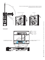
ELECTRICAL CONNECTIONS AND PROGRAMMING
⚠ Warning! Before working on the control panel, cut off the main current supply and, if present, remove any batteries.
Power supply to the control panel and control devices: 24 V AC/DC.
The features are set using the DIP switches, the adjustments using the trimmer.
All connections are quick-fuse protected.
FUSE TABLE ZL38
- Line 3.15 A-F
- Card 630 mA-F
- Gearmotor 10 A-F
- Accessories 2 A-F
Main component parts
1. Accessories fuse
2. Line fuse
3. Control panel fuse
4. Motor fuse
5. Accessories terminals
6. Radiofrequency card connector
7. SENS Trimmer:adjusting amperometric sensitivity
8. TCA Trimmer:adjusting automatic closing time
9. Functions selection Dip switch
10. Code memorisation button
11. Warning LED for radio code/automatic closing
12. Adjustment connectors for speed and deceleration
13. Connection connectors for 002LB38 card (battery charger)
14. Selection jumper for command type for button on 2-7
15. Transformer
16. Power source terminals
17. Motor terminals
18. Endpoint terminals
White
Red
Black
Brown Brown
Blue
Terminals for powering accessories:
- for 24 V AC at normal operation;
- for 24 V DC with battery operation;
Overall allowed power:40 W
230 V AC power source,
50/60 MHz frequency
Eyelet with screw
and washer for
ground connec-
tion of
Power supply

NM
PT F FC FA
NLL2T L1T
E+10 -11 12357C1 C5
GNDTXRX
7
4
7
4
C
O
M
Rallentam.Velocità
Max.Max. Med. Min. Min.
DIS. 27370
ON
2
1 3
4 5 6 7 8 9 10
NM
PT F FC FA NL
L27 L1T
E+10 -11 12357C1 C5
GNDTXRX
}
}
NM
PT F FC FA
NLL2T L1T
E+10 -11 12357C1 C5
GNDTXRX
NM
PT F FC FA
NLL2T L1T E+10 -11 12357C1 C5 GNDTXRX
COM
COM
NC
NC
Page 15 - Manual FA01237-EN - 07/2018 - © CAME S.p.A. - The contents of this manual may change, at any time, and without notice.
-
Original instructions
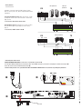
Factory wiring
The gearmotor is already connected.
To install the barrier on the right, follow the instructions in the PREPARING THE BARRIER paragraph.
Closing micro switch
Opening micro
switch Orange
Orange
White
Red
Blue
Brown
24 V DC gearmotor
Warning devices
Warning light when barrier arm is open(contact voltage rating: 24V -3W max.))
Warns that the barrier arm is open.
Flashing light and luminous cord (contact voltage
rating: 24V -23 W max. - Both flash on and o during
barrier opening and closing.
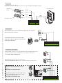
Command and control devices
STOP button (NC contact). It is for stopping the barrier while excluding automatic closing.
To resume movement, press the control button or one on another control device.
If unused, set DIP switch 9 to ON.
ONLY OPEN function from control device (NO contact).
Warning: in MAINTAINED ACTION mode, the control device must be connected to 2-3
ONLY CLOSE function from control device (NO contact).
Warning: in MAINTAINED ACTION mode, the control
device must be connected to 2-4.
Set the jumper as shown in the figure.
ONLY OPEN or OPEN-CLOSED-INVERT (step-step)
function from control device (NO contact, see DIP
switch 2).
Set the jumper as shown in the figure.

TOP TAM / TWIN
ON
2
1 3 4 5 6 7 8 9 10
NM
PT F FC FA
NL
L27 L1T
E+10 -11 12357C1 C5
GND
TXRX
NM
PT F FC FA
NLL2T L1T
E+10 -11 12357C1 C5
GNDTXRX
RX TX
+NO C NC
-+ -
NM
PT F FC FA
NLL2T L1T
E+10 -11 12357C1 C5
GNDTXRX
RX TX
Page 16 - Manual FA01237-EN - 07/2018 - © CAME S.p.A. - The contents of this manual may change, at any time, and without notice.
-
Original instructions
Safety devices
DIR photocells DELTA-S
photocells
DELTA photocells
Configure contact C1 and/or C5 (NC), input for safety
devices such as photocells, which comply with EN 12978
regulations.
C1 reopening while closing. When the boom is closing,
opening the contact causes its movement to invert until
fully opened;
If unused, shortcircuit contact 2-C1.
C5 immediate closing. Closing the boom after a vehicle
has passed through the operating area of the safety
devices.
If unused, set DIP switch 8 to ON.
Activating the radio control
Connect the RG58 cable antenna cable to the corresponding terminals .
For TOP, TAM and TWIN series transmitters with 433.92 MHz frequency, set the AF card jumper as shown in the figure .
Fit the AF card into the control board connector .
⚠Before fitting the AF card, you MUST CUT OFF THE MAINS POWER SUPPLY and, remove any emergency batteries.
AF card

ON
2
1 3 4 5 6 7 8 9 10
NM
PT F FC FA
NL
L27 L1T
E+10 -11 12357C1 C5
GND
TXRX
ON
2
1 3 4 5 6 7 8 9 10
NM
PT F FC FA
NL
L27 L1T
E+10 -11 12357C1 C5
GND
TXRX
~1°
~89°
Page 17 - Manual FA01237-EN - 07/2018 - © CAME S.p.A. - The contents of this manual may change, at any time, and without notice.
-
Original instructions
Keep the PROG programming button pressed on the control board. The programming LED will flash .
Press a button on the transmitter you wish to memorize. The LED stays lit to confirm that the transmitter is now memorized. .
PROG key Programming LED
Programming LED
Establishing the endstop points
The boom's opening and closing maneuvers must be performed with the inspection hatch closed.
Activate the barrier to check whether the boom is parallel to the road surface when closed and at about 89° when open.
To correct the vertical position (=opening), lower the barrier arm, open the
inspection door and rutn the opening mechanical stop either clockwise or
counterclockwise, then secure the stop with the counter nut.
Mechanical stop counter nut

NM
PT F FC FA
NL
L27
L1T
E+10 -11 1
2357C1 C5
GNDTXRX
C
O
M
Rallentam.Velocità
Max.Max. Med. Min. Min.
DIS. 27370
A B
{
~1°
~89°
Page 18 - Manual FA01237-EN - 07/2018 - © CAME S.p.A. - The contents of this manual may change, at any time, and without notice.
-
Original instructions
To correct the horizontal position (=closing), raise the bar, adjust the mechanical
closing stop and secure it with the counter nut.
Mechanical closing stop counter nut
Min. = minimum
Med. = medium
Max. = maximum
COM = common
Black
White
Red
To regulate the travel speed, move
faston A on Min., Med. or Max.
To adjust the slow-down speed, move
faston B to Min. or Max.
Adjusting speed

ON
2
1 3 4 5 6 7 8 9 10
NM
PT F FC FA NL
L27 L1T
E+10 -11 12357C1 C5
GNDTXRX
ON
OFF 1 2 3 4 5 6 7 8 9 10
ON
ON
2
1 3 4 5 6 7 8 9 10
NM
PT F FC FA NL
L27 L1T
E+10 -11 12357C1 C5
GNDTXRX
SENS.
A.C.T.
SENS. A.C.T.
Page 19 - Manual FA01237-EN - 07/2018 - © CAME S.p.A. - The contents of this manual may change, at any time, and without notice.
-
Original instructions
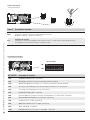
Trimmer Description of functions
SENS
Sensitivity
It adjusts the obstruction detection sensitivity during gate movement.
Minimum sensitivity (-) or maximum sensitivity (+).
A.C.T.
Automatic Closing Time
It regulates the open barrier's waiting time. Once this time elapses, a closing maneuver automatically takes place.
The waiting time may be adjusted to between 1 and 120 seconds
Trimmer adjustments
Default settings
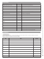
Programming the features
DIP-SWITCH Description of functions
1 ON AUTOMATIC CLOSING (1 OFF - deactivated)
2 ON ONLY OPEN from button 2-7 and/or from transmitter (with AF card fitted)
2 OFF OPEN-CLOSE-INVERT from the button on 2-7 and/or from a transmitter (with AF card fitted)
3 ON 24 V output on 10-E during the boom's movement phases and when it is in closed position
3 OFF 24 V output on 10-E during the boom's movement phases
4 ON MAINTAINED ACTION (4 OFF - deactivated)
5 ON PRE-FLASHING when opening and closing (pre-flashing duration: 5 seconds) (5 OFF - deactivated)
6 ON OBSTRUCTION DETECTION with motor idle (6 OFF - deactivated)
7 ON SLAVE piloted motor ( 7 OFF - deactivated)
8 OFF IMMEDIATE CLOSURE of the boom (8 ON - deactivated)
9 OFF TOTAL STOP (9 ON - deactivated)
10 ON BRAKING ACTION of the boom when closing (10 OFF - deactivated)

2
1
3
4
Page 20 - Manual FA01237-EN - 07/2018 - © CAME S.p.A. - The contents of this manual may change, at any time, and without notice.
-
Original instructions
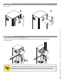
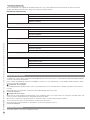
FINAL OPERATIONS
When you have completed the electrical connections and setting up, fit the control panel cover,replace the inspection hatch . Lock the hatch by
using the key .
⚠ WARNING! This operation is potentially hazardous for users, when for whatever reason, such as the boom being
badly fastened, ripped out or broken during an accident, and so on, the loosened springs no longer provide the
proper balancing action. This could lead to a sudden rotation of the boom attachment and/or of the boom itself.
RELEASING THE BOOM
⚠ This procedure must be done with the mains power cut o.
Fit the key into the lock and turn it clockwise . Manually raise the boom and lock it back into place by turning the key
counter clockwise .
Page is loading ...
Page is loading ...
Page is loading ...
Page is loading ...
-
 1
1
-
 2
2
-
 3
3
-
 4
4
-
 5
5
-
 6
6
-
 7
7
-
 8
8
-
 9
9
-
 10
10
-
 11
11
-
 12
12
-
 13
13
-
 14
14
-
 15
15
-
 16
16
-
 17
17
-
 18
18
-
 19
19
-
 20
20
-
 21
21
-
 22
22
-
 23
23
-
 24
24


CAME G3750 Installation guide
- Type
- Installation guide
- This manual is also suitable for
Ask a question and I''ll find the answer in the document
Finding information in a document is now easier with AI
Related papers
-
CAME GARD 4 Installation guide
-
-
-
CAME GARD 6000 Installation guide
-
-
-
-
-
-


