EN
SB-2-187-H (6/2015) 1 / 8
SERVICE MANUAL
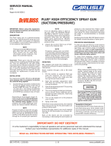
JGA-510-98FX
PRESSURE FEED HIGH VOLUME
LOW PRESSURE SPRAY GUN
MODEL NUMBER
JGA-510-98FX Full Size Gun Body
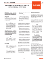
DESCRIPTION
xxx-xxx
Body Stamped
JGA-510
The JGA-HVLP pressure feed gun incor-
porates a LOW CFM HVLP air cap (#98)
which is capable of spraying a wide variety
of materials (low to medium solids), at
fluid flows typically in the 7 to 10 ounce/
minute range.
Air consumption for the #98 air cap is
approximately 11 SCFM @ 10 psi cap
pressure. Inlet air pressure of approxi-
mately 30 psi (measured at gun handle,
flowing) is required to achieve 10 psi cap
pressure. The actual air cap pressure can
be verified by using an air cap test kit (see
Accessories, page 6).
The gun model also includes a conver-
sion air baffle, which converts the higher
incoming pressure to low pressure (HVLP).
All other components, with the exception
of the air cap and baffle, are identical to
other conventional air spray JGA-510
models.
This gun model includes 300 series stain-
less steel needles and 400 series fluid tips.
See page 3 for the 300 series tip and needle
which may be ordered separately. This
gun can be used with chlorinated solvent
materials, but see page 2 for additional
warnings.
IMPORTANT: Before using this
equipment, read all safety precau-
tions and instructions. Keep for
future use.
Air Cap Stamped
98 HVLP
Baffle Stamped
Max. 30 PSI, 98
IMPORTANT: This gun may be used with
most common coating and finishing ma-
terials. It is designed for use with mildly
corrosive and non-abrasive materials. If
used with other high corrosive or abra-
sive materials, it must be expected that
frequent and thorough cleaning will be
required and the necessity for replacement
of parts will be increased.
INSTALLATION
Connect the spray gun to a clean, oil and
moisture free air supply. The air inlet
(located at the base of the gun handle)
includes a 1/4" NPS (M) connection.
Be sure to use hose with an ID of at least
5/16". DO NOT use 1/4" ID air hose which
is restrictive and will cause excessive
pressure drop (example - at 18 CFM, 25
ft. of 1/4" hose has a pressure loss of 25
psi, but 25 ft. of 5/16" hose at 18 CFM has
a pressure loss of only 8 psi).
If quick air disconnects are required, use
only higher flowing models approved for
HVLP use, such as those shown on Acces-
sories, page 6. Other types or brands may
be restrictive and may not flow enough air
for proper gun operation.
Connect the fluid hose to the fluid inlet
connection (3/8" NPS) located under the
spray head. Properly tighten with a wrench.
OPERATION
Strain material thru 60 or 90 mesh screen.
Adjust fluid pressure to deliver the desired
paint volume. Adjust air pressure and flow
to provide a uniform dispersion of atom-
ized paint throughout the pattern. Keep air
pressure as low as possible to minimize
bounce-back and overspray. Excessive
fluid flow will result in heavy center spray
patterns. Inadequate flows may cause the
pattern to split. See TROUBLESHOOTING,
page 5, if any problems occur.
For maximum transfer efficiency, do not
use more air pressure than is necessary
to atomize the material being applied. Ex-
cessive air pressure will create additional
overspray and bounce-back, reducing
transfer efficiency.
If an air cap test kit is used (see Accesso-
ries, page 6), verify air cap pressure after
acceptable atomization is achieved. Make
a note of the air cap pressure for future
reference and daily process control.
PREVENTIVE MAINTENANCE
To clean air cap and fluid tip, brush exte-
rior with a stiff bristle brush. If necessary
to clean cap holes, use a broom straw or
toothpick. Never use a wire or hard in-
strument. This may scratch or burr holes
causing a distorted spray pattern.
To clean fluid passages, remove excess
material at source, then flush with a suit-
able solvent using a device such as the
SolventSaverTM (See ACCESSORIES). Wipe
gun exterior with a solvent dampened
cloth. Never completely immerse in sol-
vent as this is detrimental to the lubricants
and packings.
SPRAY GUN LUBRICATION
Daily, apply a drop of SSL-10 spray gun
lube at trigger bearing stud (20) and the
stem of the air valve (12) where it enters the
air valve assembly (16). The shank of the
fluid needle (32) where it enters the pack-
ing nut (18) should also be oiled. The fluid
needle packing (17) should be lubricated
periodically. Make sure the baffle (5) and
retaining ring (1) threads are clean and
free of foreign matter. Before assembling
retaining ring to baffle, clean the threads
thoroughly, then add two drops of SSL-10
spray gun lube to threads. The fluid needle
spring (29) and air valve spring (11) should
be coated with a very light grease, making
sure that any excess grease will not clog
the air passages. For best results, lubricate
the points indicated, daily.
Major Repair Kit KK-4987-2
Minor Repair Kit KK-5034

EN
SB-2-187-H (6/2015)2 / 8
HAZARD CAUSE SAFEGUARDS
Fire Solvent and coatings can be highly flammable or Adequate exhaust must be provided to keep air free of
combustible especially when sprayed. accumulations of flammable vapors.
Smoking must never be allowed in the spray area.
Fire extinguishing equipment must be present in the spray area.
Solvent Spray During use and while cleaning and flushing, Wear eye protection.
solvents can be forcefully expelled from fluid and
air passages. Some solvents can cause eye injury.
Inhaling Toxic Certain materials may be harmful if inhaled, or if Follow the requirements of the Material Safety Data Sheet supplied
Substance there is contact with the skin. by your coating material manufacturer.
Adequate exhaust must be provided to keep the air free of toxic
materials.
Use a mask or respirator whenever there is a chance of inhaling
sprayed materials. The mask must be compatible with the material
being sprayed and its concentration. Equipment must be as
prescribed by an industrial hygienist or NIOSH approved.
Explosion Hazard – Halogenated hydrocarbon solvents – for example; Guns with stainless steel internal passageways may be used with
Incompatible methylene chloride and 1, 1, 1 - Trichloroethane these solvents. However, aluminum is widely used in other spray
Materials are not chemically compatible with the aluminum application equipment – such as material pumps, regulators,
that might be used in many system components. valves and cups. Check all equipment items before use and
The chemical reaction caused by these solvents make sure they can also be used safely with these solvents.
reacting with aluminum can become violent and Read the label or data sheet for the material you intend to
lead to an equipment explosion. spray. If in doubt as to whether or not a coating or cleaning
material is compatible, contact your material supplier.
General Safety Improper operation or maintenance of equipment. Operators should be given adequate training in the safe use &
maintenance of the equipment (in accordance with the require-
ments of NFPA-33, Chapter 15). Users must comply with all local
and national codes of practice & insurance company requirements
governing ventilation, fire precautions, operation, maintenance
and housekeeping. These are OSHA Sections 1910.94 and
1910.107 and NFPA-33.
Cumulative Trauma Use of hand tools may cause Pain, tingling, or numbness in the shoulder, forearm, wrist,
Disorders (CTD's) cumulative trauma disorders (“CTD’s”). hands or fingers, especially during the night, may be early
symptoms of a CD. Do not ignore them. Should you experience
CTD's, or musculo- CTD’s, when using hand tools, tend to affect the any such symptoms, see a physician immediately. Other early
skeletal disorders, upper extremities. Factors which may increase symptoms may include vague discomfort in the hand, involve
involve damage to the risk of developing a CTD include: loss of manual dexterity, and nonspecific pain in the arm.
the hands, wrists 1. High freequency of the activity. Ignoring early symptoms & continued disability.
elbows, shoulders, 2. Excessive force, such as gripping, pinching,
neck and back. or pressing with the hands and fingers.
Carpal tunnel 3. Extreme or awkward finger, wrist, or arm
syndrome and positions.
tendinitis (such 4. Excessive duration of the activity.
as tennis elbow 5. Tool vibration.
or rotor cuff 6. Repeated pressure on a bod part.
syndrome) are 7. Working in cold temperatures.
examples of CTD's. CTD's can also be caused by such activities as
sewing, golf, tennis and bowling, to name a few.
SAFETY PRECAUTIONS
This manual contains information that is important for you to know and understand. This information relates to USER SAFETY and PREVENTING
EQUIPMENT PROBLEMS. To help you recognize this information, we use the following symbols. Please pay particular attention to these sections.
Note
Information that you should pay special at-
tention to.
Important safety information – A hazard that
may cause serious injury or loss of life.
Important information that tells how to pre-
vent damage to equipment, or how to avoid a
situation that may cause minor injury.
The following hazards may occur during the normal use of this equipment.
Please read the following chart before using this equipment.
CA PROP
65
PROP 65 WARNING
WARNING: This product contains
chemicals known to the State of
California to cause cancer and birth
defects or other reproductive harm.

EN
SB-2-187-H (6/2015) 3 / 8
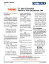
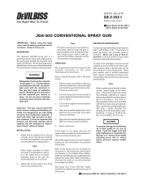
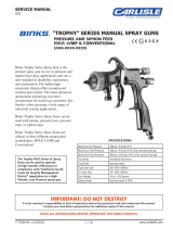
Maximum air pressure required to
assure compliance of 10 psi Max.
Cap Pressure – this reading must
be taken at the spray gun handle
inlet fitting.
Air cap number located on face of
cap – cap number must correspond
with baffle number to assure 10 psi
cap pressure.
30
Chart 1
Fluid Tip and Needle (Matched Set)
400 Gr. S.S. Tip/303 S.S. Needle
(Standard)
AV-2115-FX Tip (.042")
JGA-402-FX Needle
300 Gr. S.S. Tip with U.H.M.W.
Poly. Insert / 303 S.S. Needle (optional)
AV-4915-FX Tip (.042")
JGA-402-FX Needle
SPRAY GUN LUBRICATION (Cont'd)
A. Trigger Points
B. Packing
C. Adjusting Valves
D. Baffle Threads
E. Air Valve Cartridge
PARTS REPLACEMENT
Note
When replacing the fluid tip or
fluid needle, replace both at the
same time. Using worn parts can
cause fluid leakage. Lapped sets
are available for most pressure feed
combinations. See Chart 1. Lapped
sets are particularly recommended
with thinner, less viscous materials.
Also, replace the needle packing
at this time. Lightly lubricate the
threads of the fluid tip before reas-
sembling. Torque to 20-25 ft.lbs.
To prevent damage to the fluid tip
(3) or fluid needle (32), be sure to
either 1) pull the trigger and hold
while tightening or loosening the
fluid tip or 2) remove fluid needle
adjusting screw (27) to relieve
spring pressure against needle
collar.
FLUID INLET GASKET (6)
REPLACEMENT INSTRUCTIONS
1. Remove fluid inlet adapter (8) with
appropriate wrench.
2. Clean Loctite from gun body inlet
threads and seal area.
3. Place gasket (6) squarely onto the fluid
inlet adapter and push it down until it
is flat against the shoulder.
4. Place a couple of drops of QH-130
(medium strength blue No. 242 Loctite)
on threads before installing fluid inlet
adapter.
5. Torque fluid inlet adapter to 20-25 ft.
lbs. and tighten locknut.
C
A
E
DB
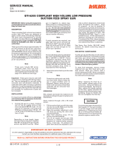
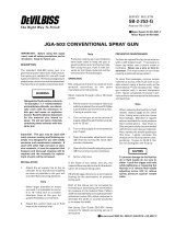
DISASSEMBLY INSTRUCTIONS –
NEW BAFFLE ASSEMBLY
The baffle design incorporates a tight,
press fit with the fluid tip, assuring a
positive air seal. With this design, the
baffle may pull away from the gun body
when the tip is removed and stay locked
onto the fluid tip. If this occurs, follow the
instructions below.
Note
A bench vise should be used for
convenience and to avoid damage
to the spray gun.
1. Secure the spray gun in a bench vise
with padded jaws, or use a rag to avoid
scratching the gun body.
2. Using a 1/2" socket, loosen the fluid tip
three (3) turns only, which will leave
about a 1/16" gap between the baffle
gasket and gun body. See Figure 2. Do
not loosen the fluid tip more than three
(3) turns, as damage may occur.
Figure 2
3. Place a 1" socket (12 pt.) over the fluid
tip so that it rests on the top surface of
the baffle. See Figure 3.
4. Press downward on the socket with
sufficient force to free the baffle from
the tip. See Figure 3.
5. The fluid tip and baffle can now be
removed normally from the gun.
Figure 3
Loosen fluid tip
3 turns only.
1/16" gap
(approx.)
Fluid Tip
Baffle
Baffle
Gasket
Bench
Vise
Figure 1 Baffle
98
Press Down
1" Socket
(12 pt.)

EN
SB-2-187-H (6/2015)4 / 8
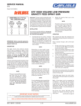
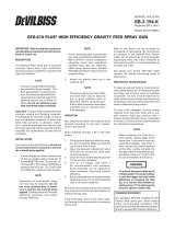
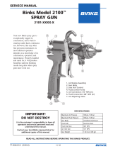
◆(Ref. No. 17) Needle Packing Detail (2 piece packing)
covered by U.S. Patent No. 5,209,501.
+Tapered edge faces out towards packing nut.
Fluid Packing
Nut
+Inner PTFE
Piece
Fluid
Needle
Outer U.H.M.W.
Poly. Piece
18
9
6
7
8
1
2
3
4
5
22 23
15
14 16
10
11
12
13
33
21
20
19
30
10
31
27
28
25
24
32
26
Air Inlet Nipple
1/4" NPS(M)
(Torque to 15 ft. lbs.)
Torque to
20-25
ft.lbs.
Torque to
20-25
ft.lbs.
Fluid Inlet
Adapter
3/8" NPS(M)
◆17
29
▲
▲Apply Loctite #242
(Medium strength, blue)
to threads.
▲
▲Apply Loctite #242
(Medium strength,
blue) to threads.
Ref. Replacement Individual
No. Part No. Description Parts Required
1 MBC-368 Retaining Ring 1
2 JGHV-101-98 Air Cap 1
3 See Chart 1 Fluid Tip 1
* 4 JGD-14-K10 Gasket Kit, Polyethylene (Kit of 10) 1
5 JGHV-457-98 Baffle and Gasket Kit 1
6 MSV-3-K10 Gasket, PTFE (Blue)(Kit of 10) 1
7 — Lock Nut 1
8 — Fluid Inlet Adapter 1
9 JGA-4044 Fluid Inlet and Nut Kit 1
•*10 JGS-72-K10 Gasket Kit, PTFE (Kit of 10) 2
*11 MBD-12-K25 Spring Kit (Kit of 25) 1
*12 JGS-431-K25 Air Valve Kit (Kit of 25) 1
•*13 JGS-26-K25 U-Cup Seal Kit (Kit of 25) 1
*14 JGA-15-K25 Washer Kit (Kit of 25) 1
*15 JGA-14-K25 Snap Ring Kit (Kit of 25) 1
16 JGS-449-1 Air Valve Assembly 1
•*17 JGV-463-K3 Packing Kit (Kit of 3) 1
18 34411-122-K10 Packing Nut Kit (Kit of 10) 1
*19 — Screw 1
PARTS LIST
Ref. Replacement Individual
No. Part No. Description Parts Required
20 JGS-478 Stud and Screw Kit 1
(Kit includes 3 studs and 5 screws)
21 JGS-477-1 Trigger, Stud and Screw Kit 1
(Kit includes 1 each)
22 JGA-132 Plug 1
23 P-MB-51 Nipple 1
24 JGA-497-1 Fan Adjustment Assembly 1
*25 — Retaining Ring 1
*26• SSG-8069-K25 O-Ring, Viton (Kit of 25) 1
27 JGS-16 Adjusting Screw 1
*28 — Spring Pad (Included with No. 29) 1
*29 MBD-19-K10 Spring Kit (Kit of 10) 1
30 — Bushing 1
31 JGA-4041 Bushing, Spring and Knob Kit 1
32 JGA-402-FX Fluid Needle 1
33 — Gun Body
* A quantity of necessary parts is included in REPAIR KIT KK-4987-2 for
complete gun repair and should be kept on hand for service convenience.
• For more limited repair, "Soft Parts Kit" KK-5034 is also available (includes
items 10, 13, 17, and 26).

EN
SB-2-187-H (6/2015) 5 / 8
TROUBLESHOOTING
CONDITION CAUSE CORRECTION
Heavy top or
bottom pattern
Heavy right or left
side pattern
Heavy center pattern
Split spray pattern
Jerky or fluttering spray
Unable to get round spray
Will not spray
Fluid leaking or dripping from
cup lid
Starved spray pattern
Excessive overspray
Excessive fog
Dry spray
Fluid leaking from packing nut
Fluid leaking or dripping from
front of gun
Horn holes plugged.
Obstruction on top or bottom of fluid tip.
Cap and/or tip seat dirty.
Left or right side horn holes plugged.
Dirt on left or right side of fluid tip.
Remedies for the top-heavy, bottom-heavy, right-heavy, and left-heavy patterns:
1. Determine if the obstruction is on the air cap or the fluid tip. Do this by making a test
spray pattern. Then, rotate the cap one-half turn and spray another pattern. If the defect
is inverted, obstruction is on the air cap. Clean the air cap as previously instructed.
2. If the defect is not inverted, it is on the fluid tip. Check for a fine burr on the edge of the
fluid tip. Remove with #600 wet or dry sand paper.
3. Check for dried paint just inside the opening; remove by washing with solvent.
Clean. Ream with non-metallic point.
Clean.
Clean.
Clean. Ream with non-metallic point.
Clean.
Fluid flow too high for atomization air.
Material flow exceeds air cap's capacity.
Spreader adjustment valve set too low.
Atomizing pressure too low.
Material too thick.
Atomization air pressure too high.
Fluid flow too low.
Spreader adjusting valve set too high.
*Loose or damaged fluid tip/seat.
Material level too low.
Container tipped too far.
Obstruction in fluid passage.
Dry or loose fluid needle packing nut.
Spreader adjustment screw not seatingproperly.
Air cap retaining ring loose.
No air pressure at gun.
Fluid needle adjusting screw not open enough.
Fluid too heavy for gravity feed.
Cup lid loose.
Dirty threads on cup or lid.
Cracked cup or lid.
Inadequate material flow.
Too much atomization air pressure.
Gun too far from work surface.
Improper stroking (arcing, gun motion too fast).
Too much or too fast-drying thinner.
Too much atomization air pressure.
Air pressure too high.
Gun tip too far from work surface.
Gun motion too fast.
Gun out of adjustment.
Packing nut loose.
Packing worn or dry.
Packing nut too tight.
Dry packing.
Fluid tip or needle worn or damaged.
Foreign matter in tip.
Fluid needle spring broken.
Wrong size needle or tip.
Balance air pressure and fluid flow.
Increase spray pattern width with
spreader adjustment valve.
Thin or lower fluid flow.
Adjust.
Increase pressure.
Thin to proper consistency.
Reduce pressure at the wall or gun.
Increase fluid flow (increases gun
handling speed).
Adjust.
Tighten or replace.
Refill.
Hold more upright.
Backflush with solvent.
Lubricate or tighten.
Clean or replace.
Tighten.
Check air supply and air lines, blow out
gun air passages.
Open fluid needle adjusting screw.
Thin material and/or change to larger tip size.
Tight lid.
Clean.
Replace cup and lid.
Back fluid adjusting screw out to first
thread, or change to larger tip size.
Reduce pressure.
Adjust to proper distance.
Move at moderate pace, parallel to
work surface.
Remix properly.
Reduce pressure.
Reduce air pressure.
Adjust to proper distance.
Slow down.
Adjust.
Tighten, do not bind needle.
Replace or lubricate.
Adjust.
Lubricate.
Replace tip and needle with lapped sets.
Clean.
Replace.
Replace.
*Most common problem.

EN
SB-2-187-H (6/2015)6 / 8
ACCESSORIES
Used to clean the inside of
hose and material passages
of the gun.
183GZ-5200
SolventSaver™
2 Gallon Galvanized
Tank Hose/Gun
Cleaners
Joins any single piece
DeVilbiss air cap with
latest version MBC-368
or MSA-1 retaining ring.
Helps prevent parts loss
and provides easier
assembly.
JGA-156-K10
Spring Clips
HAF-507
Whirlwind™
In-Line Air Filter
Removes water, oil, and debris
from the air line.
KK 5033-98
Air Cap Test Kit
The purpose of this test kit is to
measure air cap atomizing air
pressure at the center air port
of the air cap. Used to confirm
code compliance and as a daily
quality control measure.
Contains all necessary
tip, hose and nut sizes
used on or with gun.
WR-103 Wrench VS-531 Low Pressure
Fluid Strainer
100 Mesh Screen
This strainer provides a
final filter for trapping
foreign particles in the
paint supply.
Provides reduced
spring force (4 lbs.
versus 6 lbs.) for eas-
ier trigger pull.
MSA-4-K10 Fluid
Needle Spring
(replaces MBD-19)
JGA-4005
Air Adjusting Valve
Allows air adjustment
at the gun. Replaces
JGA-132 plug.
Enables user to con-
trol and reduce air
usage at the gun.
Ideal for low pressure
spraying.
P-H-5516 Air Adjust-
ing Valve
JGA-52-K10
Leather Packings
Used when abrasive
materials are sprayed
(i.e. porcelain enamel).
42884-214-K5 (3/8") &
42884-215-K10 (5/8")
Cleaning Brushes
These brushes are help-
ful in cleaning threads
and recesses of gun
body.
HAV-501
Adjusting Valve
Use to control air pres-
sure at gun.
Compatible with all
paint materials: contains
no silicone or petroleum
distillates to contami-
nate paint.
Spray Gun Lube
SSL-10 (2 oz. bottle)
HD-503
SolventSaver™
2 Quart Hose Cleaner used
to clean the inside of hose
and material passages of
gun. 2 Gallon galvanized
also available.
Quick Disconnect Approved For HVLP Guns (Air)
High Flow Ball and Ring Type.
HC-4720
1/4" NPT(F)
HC-1166
1/4" NPT(M)
HC-4419
1/4" NPS(F)
HC-4719
1/4" NPT(M)
Scrubs® are a pre-moist-
ened hand cleaner towel
for painters. No water is
needed.
29-3100 Scrubs®
Hand Cleaner Towels

EN
SB-2-187-H (6/2015) 7 / 8
NOTES

EN
SB-2-187-H (6/2015)8 / 8
Finishing Brands reserves the right to modify equipment specications without prior notice.
DeVilbiss®, Ransburg®, BGK®, and Binks® are registered trademarks of Carlisle Fluid Technologies, Inc.,
dba Finishing Brands. ©2015 Carlisle Fluid Technologies, Inc., dba Finishing Brands. All rights reserved.
WARRANTY POLICY
DeVilbiss products are covered by Finishing Brands one year materials and workmanship limited warranty.
The use of any parts or accessories, from a source other than Finishing Brands, will void all warranties.
For specic warranty information please contact the closest Finishing Brands location listed below.
DeVilbiss is part of Finishing Brands, a global leader in innovative spray nishing
technologies. For technical assistance or to locate an authorized distributor,
contact one of our international sales and customer support locations below.
USA/Canada
www.devilbiss.com
info@nishingbrands.com
Tel: 1-800-992-4657
Fax: 1-888-246-5732
United Kingdom
www.nishingbrands.eu
info@nishingbrands.eu
Tel: +44 (0)1202 571 111
Fax: +44 (0)1202 573 488
China
www.nishingbrands.com.cn
mkt@nishingbrands.com.cn
Tel: +8621-3373 0108
Fax: +8621-3373 0308
Mexico
www.nishingbrands.com.mx
sales@nishingbrands.com.mx
Tel: 011 52 55 5321 2300
Fax: 011 52 55 5310 4790
France
www.nishingbrands.eu
info@nishingbrands.eu
Tel: +33(0)475 75 27 00
Fax: +33(0)475 75 27 59
Japan
www.ransburg.co.jp
Tel: 081 45 785 6421
Fax: 081 45 785 6517
Brazil
www.devilbiss.com.br
Tel: +55 11 5641 2776
Fax: 55 11 5641 1256
Germany
www.nishingbrands.eu
info@nishingbrands.eu
Tel: +49 (0) 6074 403 1
Fax: +49 (0) 6074 403 281
Australia
www.nishingbrands.com.au
sales@nishingbrands.com.au
Tel: +61 (0) 2 8525 7555
Fax: +61 (0) 2 8525 7500
/