
Warranty Registration and Inquiry
For product warranty registration, TOTO U.S.A. Inc. recommends online warranty registration. Please visit
our web site http://www.totousa.com. If you have questions regarding warranty policy or coverage, please
contact TOTO U.S.A. Inc., Customer Service Department, 1155 Southern Road, Morrow, GA 30260
(888) 295-8134 or (678) 466-1300 when calling from outside of U.S.A.
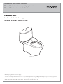
Installation and Owner’s Manual
Manual de instrucciones y del propietario
Manuel d’installation et d’utilisation
Inodoro de doble descarga
Toilettes à double chasse d’eau
CST446

2
ENGLISH
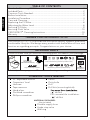
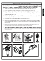
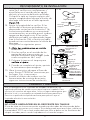
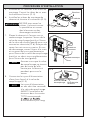
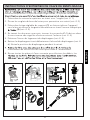
COMMON TOOLS NEEDED
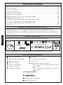
TABLE OF CONTENTS
THANKS FOR CHOOSING TOTO!
The mission of TOTO is to provide the world with healthy, hygienic and more
comfortable lifestyles. We design every product with the balance of form and
function as a guiding principle. Congratulations on your choice.
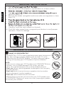
INCLUDED PARTS
Thanks for Choosing TOTO! ..............................................................................2
Included Parts ......................................................................................................2
Common Tools Needed ......................................................................................2
Before Installation ................................................................................................3
Installation Procedure ..........................................................................................4
Care and Cleaning ...............................................................................................7
Replacing the Fill Valve .......................................................................................8
Adjusting the Water Level ...................................................................................8
Servicing Fill Valve ...............................................................................................9
Servicing Flush Valve .........................................................................................10
CEFIONTECT® Cleaning Instructions ..............................................................10
Warranty..............................................................................................................11
10” adjustable wrench
Carpenters’ level
Hacksaw
Tape measure
Hand pliers
Flat head screwdriver
Phillips screwdriver
Pencil
Putty knife
Drill
Drill bits (mounting block)
- ” drill bit
For concrete/tile installation:
- ” drill bit
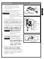
Check to make sure you have the following parts included in your package*:
* Actual parts may appear different from drawing according to the model.
Flexible supply hose
Angle stop valve
Wax ring
MATERIALS REQUIRED:
(Not Included)
Toilet
Bowl Mounting hardware
Manual
Unifit Rough-in Instruction
Rough-in Mounting Hardware
(x2) (x2) (x2) (x4) (x4) (x2)(x2)(x4)
(x2)(x2)(x2) (x2) (x2) (x1) (x1)(x1)
Push Rods (x2)
(
located on the
undersideof the tank lid)
Rough-in
(x1)
Tank to Bowl Mounting Hardware (included in Tank)
Bowl Mounting Hardware (included in Bowl)
Template
(x1)
Manual
(x1)
Unifit Rough-in
Instruction
(x1)

3
ENGLISH
BEFORE INSTALLATION
Read these instructions thoroughly before beginning work.
Please leave instructions for customers. These instructions contain
maintenance and warranty information.
If necessary, remove the existing toilet and if new construction, purge the
supply line.
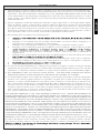
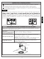
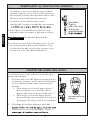
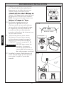
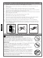
Due to the powerful performance of our Tornado, G-Max, E-Max and Power
The only means of installing these toilets in a back-to-back situation is when
builder or contractor prior to this installation.
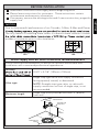
Double Combination WYE / 1/8 Bend
YES Double Sanitary Tee / Sanitary Cross
NO
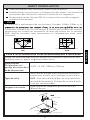
NOTICE
Water supply shut-off valve installation recommendations
Follow these recommendations to ensure an optimal and trouble-free
installation with a neat and professional appearance.
Location
4-3/4” x 5-7/8” (120mm x 150mm)
Valve type
Angle stop type valve with supply connection
facing upward, inward, or downward
NOTE: Straight stop type valve, or valve with
supply connection on front of angle stop, is not
recommended
Maximum length Angle stop must protrude less than 3” (80mm)
from wall
Centerline of
Stop valve
Finished wall
5- ”
(150mm)
Centerline of
Flange
4¾”
(120mm)
3” (80mm) MAX
“RI”

4
ENGLISH
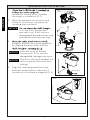
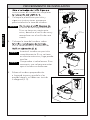
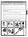
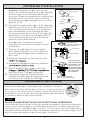
Screw
Washer
Nut
Wax seal
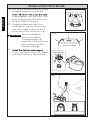
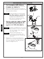
INSTALLATION PROCEDURE
1.
Installation instruction to complete
the rough-in installation (ill. 1).
2. Place the template into position and
follow its instructions to prepare for
installing the toilet bowl.
In on the Floor Flange after
wax seal is set. If this notice is
disregarded, discard the wax ring
and replace with new wax ring.
3.
Rough-In and the two mounting blocks,
by aligning the bowl outlet with the
4. Align the toilet perpendicular to the
back wall and parallel to side walls; it
should not sit crooked or diagonal (ill. 3).
Moun
ting block
Insert the toilet all the way
into position. If this notice is
disregarded, leakage may result.
Check for rocking. If needed, use
shims to prevent the toilet from
rocking.
NOTICE
NOTICE
NOTICE
ill.1
ill.2
ill. 3
Anchor

5
ENGLISH
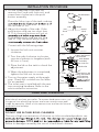
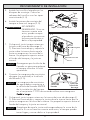
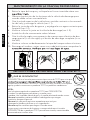
6. Install the tank-to-bowl mounting
hardware to the tank (ill. 5).
Do NOT overtighten
hardware, as it may break
the china and cause
personal injury or property
damage.
7. Place the tank upside down onto
some padding. Inspect the smaller
for a secure connection (ill. 6). Try to
tighten the nuts with your hands. If
loose, tighten the nut hand tight and
an additional 1/4 turn for the smaller
valve does not turn
and hit the tank while
tightening.
8. Connect the water supply hose (not
The water supply hose
must be connected to
tank-to-bowl installation.
TOTO recommends
supply hose.
9. Place the tank-to-bowl gasket onto
pressing down, spread the gasket
over the nut until the gasket touches
the bottom of the tank. A slight gap
between the tank bottom and the
gasket is allowable.
INSTALLATION PROCEDURE
CAUTION
Nut
Metal washer
Rubber washer
Bolt
Cap
Side-screw
Cap
Side-screw
ill. 4
5. Install the side screws to the
mounting blocks. Cover the
screw head with the provided
screw caps (ill. 4).
Flush valve nut
F
ill valve nut
ill. 6
ill. 5
NOTICE
NOTICE

6
ENGLISH
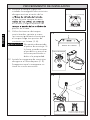
10. Pick up the tank and carefully guide
the water supply hose over the
to-bowl gasket over the inlet of the
bowl, and align the tank bolts over
the bolt holes of the bowl.
11. Using provided tank-tight nuts,
hand tighten the nuts evenly until
tank sets snugly on each of the 3
contact points on the bowl (ill. 8).
Do not overtighten
the mounting bolts.
Overtightening may
break the china and cause
personal injury and/or
property damage.
12.
hose to the angle stop (ill. 9). Make
sure that the hose is free of kinks.
CAUTION
INSTALLATION PROCEDURE
Tank-tight nut
ill. 9
Tank to Bowl
Gasket
Fill valve nut Flush valve nut
ill. 7
1
3
2
Points of Contac t
ill. 8

7
ENGLISH
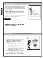
INSTALLATION PROCEDURE
Push butt
ons
Tank lid
Left Right
Full
Flush
Par
tial
Flush
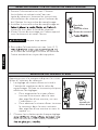
13. On the underside of the tank lid,
remove the 2 rods with lock nuts, and
screw them clockwise to the push
button assembly.
Place the lid on top of the tank, making
the left side (ill 10).
14. Adjust the length of the rods. If the
push button rods are too short (see
ill. 11a), the push buttons will not sit
If the push button rods are too long
(see ill. 11b), the push button may
Correct with the following steps:
1. Loosen the lock nuts counter-
clockwise.
2. Turn the rods clockwise to shorten,
counter-clockwise to lengthen (each
full turn is 1mm).
3. Place the lid on the tank to check the
adjustment.
4. When the adjustment is completed,
tighten the lock nut to secure.
15. Turn on the water supply at the angle
stop. Check ALL connections for leaks.
Fix as needed.
16. The toilet seat is installed with the seat
top mounting hardware. Refer to the
seat installation instruction.
ill. 10
Flush valve
Left Right
CARE AND CLEANING
DO NOT USE IN-TANK BOWL CLEANERS.
The use of high concentration of chlorine or chlorine-related products can
failure or damage caused by the use of in-tank bowl cleaners.
NOTICE
Use a detergent or non-abrasive toilet cleaner and a soft bristled
plastic brush to clean your toilet. To remove hard water stains, use
vinegar or lime dissolving cleaner and a non-scratch scour pad
made for porcelain. Allow a little contact time to allow the cleaner
to dissolve the buildup.
Clip
L
ocknut
Clockwise/
counter-clockwise
Push button
assembly
If the rod(s) is too
short, the butt
ons
are lowered
Flush valve
ill. 11a
ill. 11b If the rod(s) is too
long, the buttons
are pushed up
and water may
to toilet bowl.
Tank Lid

8
ENGLISH
REPLACING THE FILL VALVE
Flexible hose
Coupling nut
Nut
Washer
Cone seal
1. Shut off the water supply. Flush the toilet
and remove any remaining water from the
tank. Reverse the tank installation instruc-
tions to remove it from the bowl. Remove
2. -
ed portion of the shaft through the hole
in the bottom of tank.
3. Thread mounting nut onto exposed shaft
under the tank and tighten nut.
Do not over-tighten.
4. Connect the water supply (see ill. 1). Pipe
dope is not recommended. Attach the
Refer to the water level line stamp inside the
tank.
1. The water level adjustment is located
adjustments:
• To raise the water level: turn the
screwdriver clockwise, or towards
the ‘+’ indicator.
• To lower the water level: turn the
screwdriver counter-clockwise, or
towards the ‘-’ indicator.
2. Flush after each adjustment to check
ill. 1
ADJUSTING THE WATER LEVEL
CAUTION
water level adjuster
ill. 1

9
ENGLISH
1
2
1
2
3
1. Snap off the top cover by pulling from under the tab (see ill. 1).
2. Pinch the tabs of the lever arm to allow its removal (see ill. 2).
3. Snap off the adjustable rod from the bracket (1) allowing the unit to
slide to the bottom and remove the retainer tab by pulling as the arrow
indicates (3) (see ill. 3) .
4. Grab hold of the valve unit, twist 1/4 turn counterclockwise and pull the
unit out (see ill. 4).
5. Unscrew nut of the diaphragm housing (see ill. 5).
6. Remove the diaphragm from its housing by carefully pulling the edge
of the diaphragm (see ill. 6). Note the position of the diaphragm while
removing.
7. Remove the strainer from the tube with needle nose pliers (see ill. 7).
Use twisting motion while pulling to help with removal.
8.
Reinstall all parts in reverse order. Turn the water ON and check for leaks
and operation.
ill. 1 ill. 2 ill. 3
ill. 6
SERVICING THE FILL VALVE
ill. 4
ill. 5
NOTE: Due to water conditions in your area, the strainer may require periodic clean-
ing. An indication that the strainer
1
2
ill. 7

10
ENGLISH
SERVICING THE FLUSH VALVE
1.
2. Remove the tank lid and place it upside down on a clean surface.
3.
4. remove it (see ill. 1).
5. Remove the rubber seal gasket and rinse under running water to clean
(see ill. 2).
6.
7.
8.
9. Carefully, install the tank lid back on the tank.
10. Flush the toilet several times using each push button to verify proper
operation. Check for leakage.
ill. 2 ill. 3
ill. 1
No CEFIONTECT®
With
CEFIONTECT®
WHAT IS CEFIONTECT®?
CEFIONTECT® is TOTO’s super-smooth permanent glaze that prevents
debris from sticking to surfaces. Products with the letter “G” in the
number have the CEFIONTECT® glaze. This glaze, along with regular
cleaning, will help keep your TOTO product in pristine condition.
NOTE:
For best results to keep your TOTO product with CEFIONTECT® clean:
• Lavatory: Use a mild dish detergent with a clean, soft cloth.
• Toilet: Use a gel based cleaner with a soft bristled-plastic brush.
• Don’t use cleaners, polishing powders or detergents that have gritty
or coarse particles.
• Don’t use bleach, chemical thinners or products that have acid or
alkaline detergents listed as ingredients.
• Don’t use metal scrub brushes or steel wool.
Following these instructions will ensure that your TOTO product with
the CEFIONTECT® glaze will always stay intact, keeping your product
like new for years to come!
CEFIONTECT® CLEANING INSTRUCTIONS
WHAT IS CEFIONTECT®?

11
ENGLISH
WARRANTY
1. TOTO warrants its vitreous china products (“Product”) to be free from defects in materials and work-
manship during normal use when properly installed and serviced, for a period of one (1) year from date
of purchase. This limited warranty is extended only to the ORIGINAL PURCHASER of the Product and
is not transferable to any third party, including but not limited to any subsequent purchaser or owner
of the Product. This warranty applies only to TOTO Product purchased and installed in North, Central
and South America.
2. TOTO’s obligations under this warranty are limited to repair, replacement or other appropriate adjust-
ment, at TOTO’s option, of the Product or parts found to be defective in normal use, provided that
such Product was properly installed, used and serviced in accordance with instructions. TOTO reserves
the right to make such inspections as may be necessary in order to determine the cause of the defect.
TOTO will not charge for labor or parts in connection with warranty repairs or replacements. TOTO is
not responsible for the cost of removal, return and/or reinstallation of the Product.
3. This warranty does not apply to the following items:
a.
storm, etc.
b. Damage or loss resulting from any accident, unreasonable use, misuse, abuse, negligence, or
improper care, cleaning, or maintenance of the Product.
c. Damage or loss resulting from sediments or foreign matter contained in a water system.
d. Damage or loss resulting from improper installation or from installation of the Product in a harsh
(NOTE: Product model codes allow a maximum of 80 PSI. Check local codes or standards for
requirements).
e. Damage or loss resulting from electrical surges or lightning strikes or other acts which are not the
f. Damage or loss resulting from normal and customary wear and tear, such as gloss reduction,
scratching or fading over time due to use, cleaning practices or water or atmospheric conditions.
g.
h. Toilet seats of plastic, wood or metal.
4. In order for this limited warranty to be valid, proof of purchase is required. TOTO encourages warranty
registration upon purchase to create a record of Product ownership at http://www.totousa.com. Product
registration is completely voluntary and failure to register will not diminish your limited warranty rights.
5. THIS WARRANTY GIVES YOU SPECIFIC LEGAL RIGHTS. YOU MAY HAVE OTHER RIGHTS WHICH
VARY FROM STATE TO STATE, PROVINCE TO PROVINCE OR COUNTRY TO COUNTRY.
6. To obtain warranty repair service under this warranty, you must take the Product or deliver it prepaid to
a TOTO service facility together with proof of purchase (original sales receipt) and a letter stating the
problem, or contact a TOTO distributor or products service contractor, or write directly to TOTO U.S.A.,
INC., 1155 Southern Road, Morrow, GA 30260 (678) 466-1300 or (888) 295-8134, if outside the U.S.A. If,
because of the size of the Product or nature of the defect, the Product cannot be returned to TOTO,
receipt by TOTO of written notice of the defect together with proof of purchase (original sales receipt)
shall constitute delivery. In such case, TOTO may choose to repair the Product at the purchaser’s loca-
tion or pay to transport the Product to a service facility.
THIS WRITTEN WARRANTY IS THE ONLY WARRANTY MADE BY TOTO. REPAIR, REPLACEMENT OR
OTHER APPROPRIATE ADJUSTMENT AS PROVIDED UNDER THIS WARRANTY SHALL BE THE EXCLU-
SIVE REMEDY AVAILABLE TO THE ORIGINAL PURCHASER. TOTO SHALL NOT BE RESPONSIBLE FOR
LOSS OF THE PRODUCT OR FOR OTHER INCIDENTAL, SPECIAL OR CONSEQUENTIAL DAMAGES OR
EXPENSES INCURRED BY THE ORIGINAL PURCHASER, OR FOR LABOR OR OTHER COSTS DUE TO
INSTALLATION OR REMOVAL, OR COSTS OF REPAIRS BY OTHERS, OR FOR ANY OTHER EXPENSE NOT
SPECIFICALLY STATED ABOVE. IN NO EVENT WILL TOTO’S RESPONSIBILITY EXCEED THE PURCHASE
PRICE OF THE PRODUCT. EXCEPT TO THE EXTENT PROHIBITED BY APPLICABLE LAW, ANY IMPLIED
WARRANTIES, INCLUDING THAT OF MERCHANTABILITY OR FITNESS FOR USE OR FOR A PARTICU-
LAR PURPOSE, ARE EXPRESSLY DISCLAIMED. SOME STATES DO NOT ALLOW LIMITATIONS ON HOW
LONG AN IMPLIED WARRANTY LASTS, OR THE EXCLUSION OR LIMITATION OF INCIDENTAL OR CON-
SEQUENTIAL DAMAGES, SO THE ABOVE LIMITATION AND EXCLUSION MAY NOT APPLY TO YOU.
WARNING! TOTO shall not be responsible or liable for any failure of, or damage to, this Product caused
by either chloramines in the treatment of public water supply or cleaners containing chlorine (calcium
hypochlorite). NOTE: The use of a high concentrate chlorine or chlorine related products can seriously
please call TOTO at (888) 295-8134.

12
ESPAÑOL
ÍNDICE
¡GRACIAS POR ELEGIR TOTO!
La misión de TOTO es brindarle al mundo estilos de vida sanos, higiénicos y
más cómodos. Diseñamos cada producto con el balance de forma y función
como un principio rector. Felicidades por su elección.
PARTES INCLUIDAS
¡Gracias por elegir TOTO! ................................................................................12
Partes incluidas ..................................................................................................12
Herramientas comunes necesarias ...................................................................12
Antes de la instalación ......................................................................................13
Procedimiento de instalación ...........................................................................14
Cuidado y limpieza ............................................................................................17
Reemplazo de la válvula de llenado .................................................................18
Ajuste del nivel de agua ....................................................................................18
Mantenimiento de la válvula de llenado..........................................................19
Mantenimiento de la válvula de descarga .......................................................20
Instrucciones de Limpieza para CEFIONTECT® ..............................................20
Garantía ..............................................................................................................21
HERRAMIENTAS COMUNES NECESARIAS
Llave ajustable de 10”
Nivel de carpintero
Serrucho de costilla
Cinta métrica
Pinzas
Destornillador plano
Destornillador Phillips
Lapiz
Espátula
Taladro
Brocas de taladro (bloque de montaje)
Para instalación en piso de madera:
- Brocas de ”
Para instalación en concreto/azulejo:
- Brocas de ”
Revise para asegurar que tenga todas estas partes en el empaque*:
* El producto real puede variar en apariencia dependiendo del modelo.
Llave de paso ángulo
Anillo de cera
MATERIALES NECESARIOS:
(no incluida)
Inodoro
Bowl Mounting hardware
Manual
Unifit Rough-in Instruction
Piezas de montaje para Unifit
(x2) (x2) (x2) (x4) (x4) (x2)(x2)(x4)
(x2)(x2)(x2) (x2) (x2) (x1) (x1)(x1)
Varillas de Empuje
(x2)
(
ubicado debajo
de la tapa
)Rough-in
(x1)
Piezas de montaje para tanque de inodoro
(incluidas en tanque)
Piezas de montaje para taza de inodoro
(incluidas en taza)
Plantilla (x1)
Instrucciones de
instalación (x1)
Instrucciones
de Unifit
(x1)

13
ESPAÑOL
ANTES DE LA INSTALACIÓN
Lea detenidamente estas instrucciones antes de comenzar a trabajar.
Proporcione las instrucciones a los usuarios. Estas instrucciones
contienen información acerca del mantenimiento y de la garantía.
Si es necesario, retire el inodoro existente y si construcción nueva, purgar
la línea de suministro.
Debido al potente rendimiento de nuestros sistemas de descarga Tornado,
respaldo con respaldo. La única forma de instalar estos inodoros de una
manera respaldo a respaldo es cuando el desagüe del inodoro incorpora un
accesorio WYE. Póngase en contacto con su constructor o contratista antes
de la instalación.
WYE de doble combinación / doblado de 1/8
SÍ T sanitaria doble / cruz sanitaria
NO
AVISO
Recomendaciones por instalación de llave de paso
Sigue estas recomendaciones asegurar instalación sin problemas con una
apariencia ordenada y profesional.
Ubicación
(de piso y izquierda de
centro brida de piso)
4-3/4” x 5-7/8” (120mm x 150mm)
Tipo de llave de paso
Llave de paso ángulo con conexión a suministro
hacia arriba, adentro, o abajo.
NOTA: Llave de paso código o llave de paso con
conexión hacia al frente, no se recomienda.
Longitude maxima Llave de paso debe sobresalir a menos de 3”
(80mm) de la pared.
C/L* Llave de paso
Pared acabada
5- ”
(150mm)
C/L* Brida
4¾”
(120mm)
3” (80mm) MAX
* C/L es Línea de centro
“RI”

14
ESPAÑOL
Tornillo
Arandela
Tuerca
Sello de cera
PROCEDIMIENTO DE INSTALACIÓN
1.
instrucciones de instalación completar
2. Coloque la plantilla en posición y
sigue sus instrucciones a preparar
para instalación la taza de inodoro.
el anillo de cera haya asentado.
Si no se tiene en cuenta este
aviso, deseche el anillo de cera y
reemplace con el anillo de cera
nuevo.
3. Coloque la taza del inodoro sobre
con la salida de taza y la abertura de
4. Alinee el inodoro perpendicular
a la pared trasera y paralelo a las
pareds laterals; no debe ser torcido
o diagonal (il. 3).
Inserte el inodoro en posición
completamente. Si no se tiene
en cuenta este aviso, fuga puede
resultar.
Compruebe si se balancea. Si es
necesario, use calzas para evitar
que el inodoro se balancee.
AVISO
AVISO
AVISO
il. 1
il. 2
il. 3
Bloque de montaje
Ancla

15
ESPAÑOL
6. Instale las piezas de montaje del
tanque-a-taza a el tanque (il. 5).
NO APRIETE
DEMASIADO. Si no se
tiene en cuenta este
aviso, puede romper
el producto y provocar
lesiones personales o
daño a la propiedad.
7. Coloque el junto tanque-a-taza en
la tuerca de torre de descarga (il.
7). Presione hacia abajo y separe la
junta sobre la tuerca hasta que la
junta se asegure en la rosca de la
tuerca. Un pequeño espacio entre
el fondo del tanque y la junta es
normal.
Asuregarse que la válvula de
llenado no gire para golpear
el tanque mientras lo está
apretando.
8. Conecte la manguera de suministro
de agua (no proveído) a la válvula
de llenado (il. 5).
La manguera de suministro
de agua debe conectarse a
la válvula de llenado ANTES
de la instalación del tanque
en el recipiente. TOTO recomienda utilizar una manguera
9. Coloque el junto tanque-a-taza en la tuerca de torre de descarga (il.
7). Presione hacia abajo y separe la junta sobre la tuerca hasta que la
junta se asegure en la rosca de la tuerca. Un pequeño espacio entre el
fondo del tanque y la junta es normal.
Asegúrese de que la junta esté asegurada por la rosca de la
tuerca. Si no se tiene en cuenta este aviso, el tanque puede
tener fugas y causar daños a la propiedad.
PROCEDIMIENTO DE INSTALACIÓN
PRECAUCIÓN
Tuerca
Arandela de metal
Ar
andela de goma
Tornillo
Tapa
Tornillo de lado
Tapa
Tornillo
de lado
il. 4
5. Instale los tornillos laterales en los
bloques de montaje. Cubra las
cabezas del tornillos con las tapas
suministrado (il. 4)
Tuer
ca de
v
álvula de
descarga
T
uerca de
v
álvula de
llenado
il. 6
il. 5
AVISO
AVISO
AVISO

16
ESPAÑOL
10. Levante el tanque y guíe con
cuidado la manguera de suministro
de agua encima a través de los
aligne la junta tanque-a-taza a
en la taza, y aligne la pernos de
pernos en la taza.
11. Utilice las tuercas de tanque
suministrados, apriete a mano
las tuercas igualmente hasta que
el tanque haga tres puntos de
contacto con la taza. (il. 8).
No apriete demasiado
el perno de montaje. Si
lo hace, puede romper
el producto y provocar
lesiones personales o
daño a la propiedad.
12. Instale la manguera de suministro
de agua a el llave de paso (il. 9).
Asegurarse que la manguera no
tiene las curvas excesivas.
PROCEDIMIENTO DE INSTALACIÓN
Tuerca de tanque
il. 9
Junta de tanque-a-taza
Tuerca de válvula
de descarga
Tuerca de válvula
de llenado
il. 7
1
3
2
Puntos de contacto
il. 8
PRECAUCIÓN

17
ESPAÑOL
PROCEDIMIENTO DE INSTALACIÓN
Pulsadors
Tapa de tanque
Izquierda Derecho
Descarga
completa
Descar
ga
parcial
13. En la parte inferior de la tapa del tanque,
retire las 2 varillas con contratuercas y
atorníllelas en el sentido de las agujas
del reloj al conjunto del botón pulsador.
Coloque la tapa en la parte superior del
tanque, asegurándose de que el botón de
descarga total esté en el lado izquierdo
14. Ajuste la longitud de las varillas. Si las
varillas de los botones pulsadores son
demasiado cortas (vea la ilustración 11a),
los botones pulsadores no se asentarán
correctamente y es posible que el inodoro
tenga una descarga corta. Si las varillas
del botón pulsador son demasiado largas
(vea la ilustración 11b), el botón pulsador
puede activar continuamente la válvula de
descarga.
Corrija con los siguientes pasos:
antihorario.
2. Gire las varillas en el sentido de las
agujas del reloj para acortar, en
sentido antihorario para alargar (cada
vuelta completa es de 1 mm).
3. Coloque la tapa en el tanque para
4. Cuando se complete el ajuste, apriete
la contratuerca para asegurar.
15. Abra la suministro de agua al llave de
paso. Revise TODAS las conexiones por
las fugas. Fije, si necessario.
16. Instalar el asiento de inodoro con las
herramientas de montaje de asiento,
sigue sus instrucciones de instalación.
il. 10
CUIDADO Y LIMPIEZA
NO UTILICE LIMPIADORES EN EL RECIPIENTE DEL TANQUE
El uso de cloro en alta concentración o productos derivados del cloro puede dañar
seriamente los accesorios en el tanque. Este daño puede ocasionar fugas y daños en
la propiedad. TOTO no se hará responsable por fallas o daños en los accesorios del
tanque causados por el uso de limpiadores en el taza del tanque.
AVISO
Use un detergente o un limpiador de tocador no abrasivo y un
cepillo de plástico de cerdas suaves para limpiar el inodoro. Para
eliminar las manchas de agua dura, utilice vinagre o detergente que
disuelva la cal y un estropajo no raspado hecho para porcelana.
Permita un poco de tiempo de contacto para permitir que el
limpiador disuelva la acumulación.
Válvula de descarga
Descarga
completa
Descarga
parcial
Izquierda Derecho
Montaje de
pulsadores
Tapa
Válvula de
descarga
Si la varilla (s) es
demasiado cor
ta,
los botones se
bajan
Pinza
C
ontratuerca
Sentido horario/
anti-horario
il. 11a
il. 11b Si la (s) varilla (s)
es demasiado
larga, los
botones se
presionan hacia
arriba y el agua
puede continuar
taza del inodoro.

18
ESPAÑOL
REEMPLAZO LA VÁLVULA DE LLENADO
Tuerca de
acoplamiento
Tuerca
Arandela
Sello de cono
1. Cierre el suministro de agua. Descargar
el inodoro y elimine el agua restante de la
tanque. Siga las instrucciones de instalación
del tanque al revés para extraerlo de la taza.
Retire la válvula de llenado existente.
2. Instale la válvula de llenado nuevo
deslizando la parte roscada del eje aunque
3. Enrosque la tuerca de montaje en el eje
expuesto bajo el tanque y apriete la tuerca.
No apriete demasiado.
4. Conecte el suministro de agua (ver il. 1). No
se recomienda el grasa para tuberías. Fije
el tubo de llenado a la válvula sujete el otro
extremo al tubo de desbordamiento.
il. 1
AJUSTE DEL NIVEL DEL AGUA
PRECAUCIÓN
Consulte la marca que indica el nivel de agua
dentro del tanque.
1. El ajuste del nivel del agua se encuentra en
el extremo superior de la válvula de llenado.
Use un destornillador plano para realizar
ajustes:
• Para elevar el nivel del agua: gire el
destornillador en el sentido de las
agujas del reloj o hacia el indicador ‘+’.
• Para bajar el nivel del agua: gire el
destornillador en el sentido contrario a
las agujas del reloj o hacia el indicador
‘-’.
2. Descarge el inodoro déspues de cada
satisfecho con el nivel del agua, vuelva a
Ajustador del nivel
del agua
il. 1

19
ESPAÑOL
MANTENIMIENTO DE LA VÁLVULA DE LLENADO
1
2
1
2
3
1. Desprenda la cubierta superior tirando de debajo de la pestaña
(ver il. 1).
2. Presione las pestañas del brazo de palanca para permitir su extracción.
(ver il. 2).
3. Desprenda la barra ajustable del soporte (1) permitiendo que la unidad
se deslice hacia la parte inferior y retire la pestaña del retén tirando como
(3) (ver il. 3) .
4. Mientras sostiene la válvula con una mano, gire la tapa 1/4 de vuelta en
sentido contrario a las manecillas del reloj y retírela (ver il. 4).
5. Destornille la tuerca de la cubierta del diafragma (ver il. 5).
6. Retire la diafragma desde la cubierta tirando con cuidado del borde del
diafragma (ver il. 6). Tenga en cuenta la posición del diafragma mientras lo
extrae.
7. Retire el colador desde el tubo con pinzas de punto (ver il. 7). Use el
movimiento giratorio mientras tira para ayudar con la extracción.
8. Enjuague todas las partes con agua corriente para eliminar cualquier
residuo o película. Vuelva a instalar todas las piezas en orden inverso. Abra
il. 1 il. 2 il. 3
il. 6
il. 4
il. 5
NOTA: Debido a las condiciones del agua en su área, el colador puede requerir una
agua del tubo de llenado.
1
2
il. 7

20
ESPAÑOL
MANTENIMIENTO DE LA VÁLVULA DE DESCARGA
1. Cierre el suministro de agua y descarge el inodoro.
2. Retire la tapa del tanque y colóquela en forma invertida sobre una
3. Observe la posición de los botones de la válvula de descarga para
cuando deba volver a ensamblarla.
4. Gire la mitad superior de la válvula en sentido contrario a las manecil-
las del reloj y extraiga la válvula (ver il. 1).
5. Retire la junta de sello de goma y enjuáguela con agua corriente para
limpiarla (ver il. 2).
6. Vuelva a colocar la junta en la válvula de descarga (ver il. 3).
7. Instale la válvula nuevamente sobre la base.
8. Gire la válvula según sea necesario de manera que el botón de des-
carga parcial (is on the right) y el botón de descarga complete (is on
the left).
9. Vuelva a colocar cuidadosamente la tapa del tanque sobre el mismo.
10. Descarge el inodoro varias veces con cada botón para comprobar la
il. 2 il. 3
il. 1
NOTICE
INSTRUCCIONES DE LIMPIEZA PARA CEFIONTECT®
Sin
CEFIONTECT®
Con
CEFIONTECT®
BLANQUEAD
DILUYENTE
DE PINTURA
¿QUÉ ES CEFIONTECT®?
CEFIONTECT® es el esmalte permanente súper suave de TOTO que evita que
número tienen el esmalte CEFIONTECT®. Este esmalte, junto con una limpieza
regular, ayudará a mantener su producto TOTO en perfectas condiciones.
NOTA:
Para la limpieza regular de su producto TOTO con CEFIONTECT®:
• Lavabo: Use detergente para platos y un paño suave.
• Inodoro: Use limpiador a base de gel y un cepillo plástico de cerdas suaves.
• No use limpiadores, polvos pulidores o detergentes que tengan
partículas arenosas o gruesas.
• No use lejía, diluyentes químicos o productos que incluyan
detergentes ácidos o alcalinos en sus ingredientes.
• No use cepillos metálicos para fregar ni lana de acero.
Si sigue estas instrucciones de limpieza, se asegurará de que el esmalte
CEFIONTECT® de su producto TOTO permanezca intacto, manteniendolo
hermoso durante muchos años.
Page is loading ...
Page is loading ...
Page is loading ...
Page is loading ...
Page is loading ...
Page is loading ...
Page is loading ...
Page is loading ...
Page is loading ...
Page is loading ...
Page is loading ...
Page is loading ...
-
 1
1
-
 2
2
-
 3
3
-
 4
4
-
 5
5
-
 6
6
-
 7
7
-
 8
8
-
 9
9
-
 10
10
-
 11
11
-
 12
12
-
 13
13
-
 14
14
-
 15
15
-
 16
16
-
 17
17
-
 18
18
-
 19
19
-
 20
20
-
 21
21
-
 22
22
-
 23
23
-
 24
24
-
 25
25
-
 26
26
-
 27
27
-
 28
28
-
 29
29
-
 30
30
-
 31
31
-
 32
32


Toto 01 Installation guide
- Category
- Sanitary ware
- Type
- Installation guide
Ask a question and I''ll find the answer in the document
Finding information in a document is now easier with AI