
Quality made by
Endress+Hauser
ISO 9001
BA 343C/07/en/11.03
51512512 CleanFit CPA 451
Retractable Process Assembly
Operating Instructions


CleanFit CPA 451
Endress+Hauser 3
Table of contents
1 Safety instructions . . . . . . . . . . . . . . 4
1.1 Designated use . . . . . . . . . . . . . . . . . . . . . . . . 4
1.2 Installation, commissioning and operation . . . 4
1.3 Operational safety . . . . . . . . . . . . . . . . . . . . . . 4
1.4 Return . . . . . . . . . . . . . . . . . . . . . . . . . . . . . . . 4
1.5 Notes on safety icons and symbols . . . . . . . . . 5
2 Identification . . . . . . . . . . . . . . . . . . . 6
2.1 Device designation . . . . . . . . . . . . . . . . . . . . . 6
2.2 Scope of delivery . . . . . . . . . . . . . . . . . . . . . . . 6
3 Installation. . . . . . . . . . . . . . . . . . . . . 7
3.1 Incoming acceptance, transport, storage . . . . 7
3.2 Installation conditions . . . . . . . . . . . . . . . . . . . 7
3.3 Installation instructions . . . . . . . . . . . . . . . . . . 9
3.4 Post-installation check . . . . . . . . . . . . . . . . . . 13
4 Operation . . . . . . . . . . . . . . . . . . . . . 14
4.1 First commissioning . . . . . . . . . . . . . . . . . . . . 14
4.2 Operating elements . . . . . . . . . . . . . . . . . . . . 14
4.3 Assembly operation . . . . . . . . . . . . . . . . . . . . 15
5 Maintenance . . . . . . . . . . . . . . . . . . 16
5.1 Cleaning of the assembly . . . . . . . . . . . . . . . 16
5.2 Cleaning of the sensor . . . . . . . . . . . . . . . . . . 16
5.3 Cleaning agents . . . . . . . . . . . . . . . . . . . . . . . 17
6 Accessories . . . . . . . . . . . . . . . . . . . 18
6.1 Accessories kits . . . . . . . . . . . . . . . . . . . . . . . 18
6.2 Sensors . . . . . . . . . . . . . . . . . . . . . . . . . . . . . 18
6.3 Welded fitting . . . . . . . . . . . . . . . . . . . . . . . . . 18
6.4 Profiling plates . . . . . . . . . . . . . . . . . . . . . . . . 19
6.5 Documentation . . . . . . . . . . . . . . . . . . . . . . . . 19
7 Trouble-shooting. . . . . . . . . . . . . . . 20
7.1 Replacing damaged parts . . . . . . . . . . . . . . . 20
7.2 Replacing seals . . . . . . . . . . . . . . . . . . . . . . . 20
7.3 Spare part kits . . . . . . . . . . . . . . . . . . . . . . . . 22
7.4 Return . . . . . . . . . . . . . . . . . . . . . . . . . . . . . . 23
7.5 Disposal . . . . . . . . . . . . . . . . . . . . . . . . . . . . . 23
8 Technical data . . . . . . . . . . . . . . . . . 24
8.1 Environment . . . . . . . . . . . . . . . . . . . . . . . . . . 24
8.2 Process . . . . . . . . . . . . . . . . . . . . . . . . . . . . . 24
8.3 Mechanical construction . . . . . . . . . . . . . . . . 25
Index . . . . . . . . . . . . . . . . . . . . . . . . . . . . . 26

Safety instructions CleanFit CPA 451
4Endress+Hauser
1Safety instructions
1.1 Designated use
The manually or pneumatically operated retractable assembly Cleanfit CPA 451 is
designed for installing pH sensors in tanks and pipes.
Its mechanical design permits its use in pressurised systems (see "Technical data").
Any other use than the one described here compromises the safety of persons and the
entire measuring system and is, therefore, not permitted.
The manufacturer is not liable for damage caused by improper or non-designated use.
1.2 Installation, commissioning and operation
Please note the following items:
•Installation, electrical connection, commissioning, operation and maintenance of the
measuring system must only be carried out by trained technical personnel.
The technical personnel must be authorised for the specified activities by the system
operator.
•Technical personnel must have read and understood these Operating Instructions
and must adhere to them.
•Before commissioning the entire measuring point, check all the connections for
correctness. Ensure that electrical cables and hose connections are not damaged.
•Do not operate damaged products and secure them against unintentional
commissioning. Mark the damaged product as being defective.
•Measuring point faults may only be rectified by authorised and specially trained
personnel.
•If faults can not be rectified, the products must be taken out of service and secured
against unintentional commissioning.
•Repairs not described in these Operating Instructions may only be carried out at the
manufacturer’s or by the Endress+Hauser service organisation.
1.3 Operational safety
The assembly has been designed and tested according to the state of the art and left
the factory in perfect functioning order.
Relevant regulations and European standards have been met.
As the user, you are responsible for complying with the following safety conditions:
•Installation instructions
•Local prevailing standards and regulations.
1.4 Return
If the assembly has to be repaired, please return it cleaned to the Endress+Hauser
sales centre responsible.
Please use the original packaging, if possible.
Please enclose the completed Dangerous Goods sheet (copy the second last page of
these Operating Instructions) with the packaging and also the shipping documents.
No repair without completed Dangerous Goods sheet!

CleanFit CPA 451 Safety instructions
Endress+Hauser 5
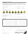
1.5 Notes on safety icons and symbols
Warning!
This symbol alerts you to hazards. They can cause serious damage to the instrument or
to persons if ignored.
Caution!
This symbol alerts you to possible faults which could arise from incorrect operation.
They could cause damage to the instrument if ignored.
Note!
This symbol indicates important items of information.

Identification CleanFit CPA 451
6Endress+Hauser
2 Identification
2.1 Device designation
2.1.1 Nameplate
You can identify the assembly version by the order code on the nameplate. Please
compare this code with your order.
You can find possible assembly versions and the resulting order codes in the product
structure.
2.1.2 Product structure
* not applicable: CPF 81/82-xx3 with 58 mm (2.28") immersion depth
2.2 Scope of delivery
The scope of delivery comprises:
•CleanFit assembly (ordered version)
•Operating Instructions (English).
If you have any questions, please contact your supplier or your Endress+Hauser sales
centre responsible (see back page of these Operating Instructions).
C07-CPA451xx-18-07-00-en-001.eps
Fig. 1: Example of a nameplate
Sensor lift / Immersion depth
A Short lift, Immersion depth approx. 170 mm / 6.69" (process connections A and B only)
B Long lift, Immersion depth approx. 270 mm / 10.63"
Sensor type / Connection
3 For CPA 81/82* with NPT ¾", Sensor length approx. 140 mm / 5.51"
Process connection
A G2 internal thread
B G2 internal thread with welded fitting h = 50 mm / 1.97"
C Flange DN 50 / PN 16 acc. to EN 1092/1
D Flange ANSI 2" / 150 lbs
CPA 451- complete order code
ENDRESS+HAUSER
CLEANFIT CPA 451
order code:
serial no.:
spec.
pressure: PN=10bar T=80°C
CPA451-A2A
2 11859 05C79

CleanFit CPA 451 Installation
Endress+Hauser 7
3 Installation
3.1 Incoming acceptance, transport, storage
•Make sure the packaging is undamaged!
Inform the supplier about damage to the packaging.
Keep the damaged packaging until the matter has been settled.
•Make sure the contents are undamaged!
Inform the supplier about damage to the delivery contents.
Keep the damaged products until the matter has been settled.
•Check that the scope of delivery is complete and agrees with your order and the
shipping documents.
•The packaging material used to store or to transport the product must provide shock
protection and humidity protection. The original packaging offers the best protection.
Also, keep to the approved ambient conditions (see "Technical data").
•If you have any questions, please contact your supplier or your Endress+Hauser
sales centre responsible (see back page of these Operating Instructions).
3.2 Installation conditions
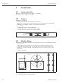
3.2.1 Dimensions
C07-CUA451xx-06-07-en-003.eps
Fig. 2: Assembly with welding neck (short
lift)
* Dimensions depend on sensor, see
below
C07-CUA451xx-06-07-00-en-002.eps
Fig. 3: Assembly with flange connection
(long lift)
* Dimensions depend on sensor, see
below
C07-CUA451xx-06-07-00-en-001.eps
Fig. 4: Assembly in service position
** Assembly version with short lift
(see product structure)
*** There must be additional space of 350 mm (13.78") for sensor installation!
*
32 /
1.26 227 /
8.94
53 /
2.09
85 / 3.35
Ø 49.5/
Ø 1.95 mm /
inch
1/
0.04
*
32 /
1.26
105 / 4.13
227 /
8.94
53 /
2.09
85 / 3.35
Ø 49.5/
Ø 1.95
mm /
inch
105
4.13
100
3.94
191** / 296
7.52** / 11.65
443** / 548
17.44** / 21.57 + 350 / 13.78* **
mm
inch
* Dimension acc. to sensor type:
CPF 81-xx2: 6 mm (0.24")
CPF 81/82-xx1: 17 mm (0.67")

Installation CleanFit CPA 451
8Endress+Hauser
3.2.2 Process connections
C07-CUA451xx-04-07-00-en-001.eps
Abb. 5: Process connections
A Internal thread G2
B Internal thread G2 with welded fitting
C Flange DN 50 / PN 16 and Flange ANSI 2" / 150 lbs
a: DN 50: Ø 125 (4.92"), ANSI 2": Ø 120.7 (4.75")
b: DN 50: Ø 165 (6.50"), ANSI 2": Ø 152.4 (6.00")
3.2.3 Notes on installation
The assembly is designed for installation on tanks and pipes. Suitable nozzles must be
available for this.
Installation place
Install the assembly at places with constant flow. The minimum pipe diameter is DN 80.
C07-CPA451xx-11-07-00-de-001.eps
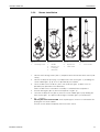
Fig. 6: Permissible and impermissible sensor installation positions
1 Ascending pipe, best position
2 Horizontal pipe, sensor top down, impermissible due to air cushion or foam bubble forming
3 Horizontal pipe, installation with permissible emitting angles (acc. to sensor version)
4 Overhead installation, impermissible due missing electrolyte contact of the internal lead
5 Down pipe, impermissible
Note!
•Do not install the assembly at places, where air cushions or foam bubbles can be
formed or where suspended particles can settle on the sensor optics (→Fig. 6).
•Measuring errors can occur, if:
– the electrode is not immersed into the medium
– suspended particles are settled on the glass membrane of the electrode
– the electrode is installed horizontal or overhead (the min. installation angle is 15° for
the internal lead to have electrolyte contact).
CA B
2"
32 / 1.26
a
b
mm / inch
5
3
4
1
2
3
Detail A,
(top view)
Detail A, rotated
(side view)
90°

CleanFit CPA 451 Installation
Endress+Hauser 9
Orientation
Caution!
•Avoid a siphon effect1 at the rinse chamber outlet when installing with inclined
orientation. The inlet to the rinse chamber must be from below.
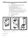
3.3 Installation instructions
3.3.1 Measuring system
A complete measuring system comprises:
•CleanFit CPA 451 assembly
•OrbiPac W CPF 81/82 pH/ORP electrode
•Liquisys M CPM 223/253 transmitter
C07-CPA451xx-14-07-00-xx-001.eps
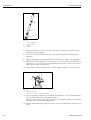
Fig. 9: Measuring system
1 OrbiPac W CPF 81/82 pH / Redox electrode
2 Liquisys M CPM 223/253
3 CleanFit CPA 451
4 Medium flow direction
C07-CPA451xx-11-07-00-xx-003.eps
Fig. 7: Ascending pipe and tank side installation
αmin. 15°
1 Medium flow direction
C07-CPA451xx-11-07-00-xx-002.eps
Fig. 8: Tank top installation
αmin. 15°
1 Medium flow direction
α
190°
α
α α
1) Siphon effect: line emptied by vacuum
12
3
4

Installation CleanFit CPA 451
10 Endress+Hauser
3.3.2 Installing the assembly into the process
Move the assembly into the "Service" position (outer sleeve inserted in the assembly)
and secure the assembly to the tank or the piping using your selected process
connection.
Note!
Depending on the process connection, please observe the following:
•Check the installation of the flange seal between the flanges.
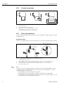
3.3.3 Rinse water connection (optionally)
You can rinse the sensor in the Service position with a second ball valve for the rinse
chamber (see Accessories).
Connect the rinse water pipe to the designated rinse nozzle. Both rinse nozzles on the
assembly are identical. Use one as an inlet and the other as an outlet.
Operate the rinse water connection of the assembly with a water pressure of 2 to
max. 6 bar (29 to 87 psi). In addition, install a non-return valve and a dirt trap (100 µm)
in the water supply line (at the inlet to the assembly).
Caution!
If it is possible for the water pressure to rise above 6 bar (87 psi, including any transient
pressure surges), install a pressure reducing valve upstream. Otherwise the assembly
may be damaged.
Besides water, other or additional cleaning solutions may be used in the rinse chamber.
Pay attention to the material resistance of the assembly and comply with the maximum
permitted temperatures and pressures.
C07-CUA451xx-15-07-06-xx-001.eps
Fig. 10: Assembly in measuring mode (ball valve
open)
1
2
3
4
5
6
7
8
9
Hand lever for ball valve open/close
Process connection (Flange DN 50 / PN 16)
Outer sleeve
Locking pin
Fastening screws
Bayonet joint
Handle
Lubricator nipple
Air relief valve resp. rinse water connection
1
2
3
4
5
6
7
8
9

CleanFit CPA 451 Installation
Endress+Hauser 11
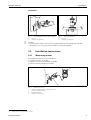
3.3.4 Sensor installation
1. Loosen the fastening screws (Pos. 1) and place them somewhere within reach (and
safely).
2. Loosen the bayonet joint (Fig. 12) and pull the outer sleeve (pos. 7) including the
sensor holder (pos. 8) up as far as possible by the handles.
3. Close the ball valve! To do this, press the hand lever (pos. 5) down as far as
possible (only possible in one direction!).
When the ball valve is closed the assembly is sealed off from the process.
4. Pull the locking pin (pos. 4) out of the bayonet nut (pos. 6).
5. Unscrew the bayonet nut (pos. 6) from the sensor holder (pos. 8) by holding the
outer sleeve (pos. 7) in place and turning the handles (pos. 2) anticlockwise.
6. Hinweis!
Do not pull at the sensor cable, when replacing the sensor! Use the bracket for
pulling out the sensor holder.
Pull the sensor holder completely out of the outer sleeve.
C07-CXA451xx-11-07-06-xx-001.eps
Fig. 11:
1 Fastening screws
C07-CXA451xx-11-07-06-xx-002.eps
Fig. 12:
2 Handles
3 Bayonet joint
4 Locking pin
5 Hand lever
C07-CXA451xx-11-07-06-xx-003.eps
Fig. 13:
6 Bayonet nut
7 Outer sleeve
C07-CXA451xx-11-07-06-xx-004.eps
Fig. 14:
8 Sensor holder
1
2
3
4
5
6
7
8

Installation CleanFit CPA 451
12 Endress+Hauser
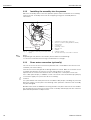
7. Screw the ring nut on the sensor (Fig. 15) and the sensor firmly into the internal
thread of the sensor holder.
8. Press the sensor holder back into the outer sleeve and screw the bayonet nut
clockwise.
9. Plug the locking pin into the drill holes of the bayonet nut and the sensor holder.
10. Open the ball valve and press the outer leeve as far as possible in the direction of
the process. This is easier when you lubricate the outer leeve. Please refer to the
notes of the chapter "Maintenance".
11. Lock the bayonet joint and secure the sensor holder using the fastening screws.
12. You can change the position of the upper assembly part, e.g. for another position
of the handles (due to the installation situation).
Loosen the retaining screws (Fig. 16) and turn the complete upper assembly part
around its own axis to the desired position.
13. Lock this position by tightening the 2 screws until the assembly part cannot turn any
more.
C07-CPA451xx-11-07-06-xx-005.eps
Fig. 15:
9 Sensor holder with
internal thread
10 Sensor
11 Ring nut
C07-CXA451xx-11-07-06-xx-008.eps
Fig. 16:
14 Retaining screw(s)
(2 screws, only one is visible in the figure)
9
10
11
14

CleanFit CPA 451 Installation
Endress+Hauser 13
3.4 Post-installation check
•After installation, check that all connections are firmly in position and leak-tight.
•Ensure that the hoses of the rinse water connections (optionally) cannot be removed
without force.
•Check all hoses for damage.

Operation CleanFit CPA 451
14 Endress+Hauser
4Operation
4.1 First commissioning
Before the first commissioning, make sure of the following items:
•all seals are correctly seated (on the assembly and process connection)
•the sensor is correctly installed and connected
•the water supply line is correctly connected to the rinse connections (if fitted)
Warning!
Danger of squirting medium.
Before applying the process pressure to the assembly, make sure the connections are
correctly fitted. If you use the delivered ball valve for the rinse chamber as a vent valve,
ensure the counter side of the rinse chamber is closed by the dummy plug. Otherwise
the assembly may not be put into the process!
4.2 Operating elements
C07-CXA451xx-19-07-06-xx-001.eps
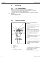
Fig. 17: Operating elements
1 Hand lever
2Handles
3 Retaining screw(s)
4 Bracket
5 Fastening screws
6 Locking pin
7 Stop bolt lock on the bayonet joint
8 Lubricator nipple
You have the following options for
operating:
•Hand lever
Use this to open or close the ball valve.
•Stop bolt locks and screws
Use these to lock the sensor holder in
the "measuring" position.
•Handles
You can change the alignment of the
sensor in the process by turning the
upper part of the assembly around its
own axis using the handles (bayonet
joint engaged, fastening screws
screwed in and retaining screws
released).
•Retaining screws
Use these to lock the upper part of the
assembly in the desired position.
•Bracket
Use the bracket for pulling out the outer
leeve. Never pull at the sensor cable!
The bracket has a mark on one side.
This enables you to identify the position
of the sensor when installing it into the
assembly (see "Sensor installation"
chapter).
•Locking pin
Use this pin to secure the threaded joint
of the bayonet nut and the sensor
holder. Now the joint cannot get loose
when adjusting the sensor, pulling out
the outer sleeve or inserting it.
•Lubricator nipple
Use this to lubricate parts of the outer
sleeve ( see "Maintenance" chapter)
1
2
3
4
5
2
6
7
8

CleanFit CPA 451 Operation
Endress+Hauser 15
4.3 Assembly operation
Warning!
•You can only operate the retractable assembly manually up to a pressure of 2 bar
(29 psi)! If the operating pressure is higher, you have to switch off the process before
moving the assembly.
•Never loosen the fastening screws at process pressures above 2 bar (29 psi)!
•At process pressures of up to 2 bar (29 psi), ensure that the bayonet joint does not
open when you loosen the fastening screws. Otherwise there is a risk of the screws
uncontrollably "shooting out" as a result of the pressure!
•Always use an Allen key to loosen and lock the screws and keep it in your hand from
turning the first screw until the last screw has been turned. This ensures that you have
the screws under control.
•Always lock the sensor holder with the bayonet joint and the fastening screws.
Otherwise, the sensor holder may exit uncontrolled as a result of the process pressure
and injure somebody.
Move from the "Service" position to the "Measuring" position
1. Open the ball valve.
2. Push the sensor holder as far as possible in the direction of the process.
3. Lock the sensor holder using the bayonet joint and the fastening screws. This
prevents the sensor holder from returning inadvertently into the "Service" position.
4. If necessary, turn the upper part of the assembly around its own axis using the
handles to align the sensor. Lock the desired position with the retaining screws.
Move from the "Measuring" position to the "Service" position
1. Loosen the fastening screws using an Allen key.
2. Open the bayonet joint.
3. Pull the sensor holder out as far as possible ("Service" position).
4. Close the ball valve.
5. Complete the necessary service tasks.

Maintenance CleanFit CPA 451
16 Endress+Hauser
5 Maintenance
Warning!
Risk of injury!
Before starting maintenance work on the assembly, make sure that the process line and
the tank are depressurised, empty and rinsed.
Move the assembly to the "Service" position.
5.1 Cleaning of the assembly
To ensure a reliable measurement, the assembly and the sensor must be cleaned at
regular intervals. The frequency and intensity of the cleaning operation depend on the
process medium.
All parts in contact with the medium, e.g. the sensor and the sensor holder, must be
cleaned at regular intervals. Remove the sensor1.
•Remove light dirt using suitable cleaning agents (see chapter "Cleaning agents").
•Remove severe fouling with a soft brush and a suitable cleaning agent.
•Remove persistant fouling by soaking in a liquid cleaner and if neccessary by
cleaning with a soft brush.
Note!
Grease the outer sleeve to ensure the assembly moves in and out smoothly. Syntheso
Glep 1 (from Klüber) is a suitable grease. Also grease the area between the O-rings with
the aid of the lubricator nipple.
5.2 Cleaning of the sensor
You have to clean the sensor:
•before every calibration
•regularly during operation
•before being returned for repair
You can remove and clean the sensor manually or perform cleaning in automatic
operation2 via the rinse connection.
Note!
•Do not use any abrasive cleaning agents. This can lead to irreparable damage of the
sensor.
•After cleaning the sensor, rinse the rinse chamber of the assembly with copious
amounts of water. Otherwise, remaining residues of cleaning agent can corrupt
measurement.
•If required, re-calibrate after cleaning.
1) in reverse sequence of operations to the installation procedure
2) with the corresponding assembly equipment only

CleanFit CPA 451 Maintenance
Endress+Hauser 17
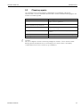
5.3 Cleaning agents
The selection of the cleaning agent is dependent on the degree and type of
contamination. The most common contaminations and the suitable cleaning agents are
listed in the following table.
Caution!
Do not use organic solvents containing halogen or acetone. These solvents could
destroy plastic components on the assembly or the sensor and it is also partly
suspected that they cause cancer (e.g. Chloroform).
Type of contamination Cleaning agent
Greases and oils Substances containing tensides (alkaline) or water-soluble
organic solvents (e.g. Ethanol)
Calciferous deposits, metal hydroxide
deposits, lyophobic biological deposits
approx. 3% hydrochloric acid
Sulphide deposits Mixture of 3% hydrochloric acid and thiocarbamide
(commercially available)
Protein deposits Mixture of 3% hydrochloric acid and pepsin (commercially
available)
Fibres, suspended substances Water under pressure, poss. with surface-active agents
Light biological deposits Water under pressure

Accessories CleanFit CPA 451
18 Endress+Hauser
6 Accessories
6.1 Accessories kits
❑Ball valve for rinse connection; order no. 51512982
❑O-ring set, Viton; order no. 51512981
6.2 Sensors
❑OrbiPac W CPF 81/82
compact electrode for pH and ORP measurements
Application: wastewater treatment, drinking water and condensate conditioning
ordering acc. to product structure, see Technical Information
Hinweis!
The following versions are not applicable:
– CPF81-xx3 with 58 mm (2.28") immersion depth
– CPF82-xx3 with 58 mm (2.28") immersion depth
C07-CPF81xxx-00-05-06-xx-001.eps
Fig. 18: OrbiPac W CPF 81
6.3 Welded fitting
❑Welded fitting for pipe diameters of more than 80 mm (3.15"), with combination flange
DN 50 / ANSI 2":
– Bore holes for DN 50 flange: 4 x 90° Ø18 (0.71") on hole circle Ø125 (4.92")
– Bore holes for ANSI 2" flange: 4 x 90° Ø19 (0.75") on hole circle Ø121 (4.76")
Flange seal, 4 screws M16x60, 4 nuts M16 incl. washers, stainless steel 1.4571
(AISI 316Ti);
order no. 50080249
C07-CUA451xx-00-07-00-en-001.eps
Fig. 19: Welded fitting
D: Marks for the bore holes of the DN 50 flange
D
D
D
D
M16x60
75 / 2.95
93 / 3.66 Ø 165 / 6.50
mm / inch

CleanFit CPA 451 Accessories
Endress+Hauser 19
6.4 Profiling plates
❑Profiling plates for welded fittings;
order no. 51513623
6.5 Documentation
❑Technical Information OrbiPac W CPF 81/82, TI 191C/07 (order no. 51500045)

Trouble-shooting CleanFit CPA 451
20 Endress+Hauser
7 Trouble-shooting
7.1 Replacing damaged parts
Warning!
Damage to the assembly which affects the pressure safety must only be repaired by
authorised technical personnel.
After every repair and maintenance activity, suitable measures must be taken to test
whether the assembly shows any signs of leaking. The assembly must then correspond
to the specifications stated in the technical data.
Replace all other damaged components immediately. To order accessories and spare
parts, please use the "Accessories" and "Spare parts" chapters or contact your E+H
Sales Center.
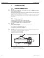
7.2 Replacing seals
•Keep the sealing surfaces of the assembly free of dirt.
•Remove deposits clinging to the assembly from time to time.
•In the event of leakages, contact your E+H Sales Center.
Warning!
Risk of medium leaking out!
Seals must only be replaced by authorised technical personnel.
You can replace the following seals (Fig. 20):
•O-ring Viton, in contact with the medium
•O-rings Viton, not in contact with the medium
Warning!
The assembly has to be separated from the process connection to replace the seals.
For this purpose, the following conditions must be met:
•The process must be switched off.
•Piping or container must be empty.
C07-CXA451xx-00-07-07-xx-001.eps
Fig. 20: Seals
1 O-ring Viton, in contact with the medium
2 O-rings Viton, not in contact with the medium
12
Page is loading ...
Page is loading ...
Page is loading ...
Page is loading ...
Page is loading ...
Page is loading ...
Page is loading ...
Page is loading ...
-
 1
1
-
 2
2
-
 3
3
-
 4
4
-
 5
5
-
 6
6
-
 7
7
-
 8
8
-
 9
9
-
 10
10
-
 11
11
-
 12
12
-
 13
13
-
 14
14
-
 15
15
-
 16
16
-
 17
17
-
 18
18
-
 19
19
-
 20
20
-
 21
21
-
 22
22
-
 23
23
-
 24
24
-
 25
25
-
 26
26
-
 27
27
-
 28
28


ENDRESS+HAUSER Cleanfit CPA451 Operating Instruction
- Type
- Operating Instruction
- This manual is also suitable for
Ask a question and I''ll find the answer in the document
Finding information in a document is now easier with AI
Related papers
-
ENDRESS+HAUSER Liquisys M CLM223 Operating Instructions Manual
-
ENDRESS+HAUSER Liquistation CSF48 Datasheet
-
ENDRESS+HAUSER Smartec S CLD132 Operating Instructions Manual
-
-
-
-
-
ENDRESS+HAUSER Deltabar S PMD 75 Brief Operating Instructions
Other documents
-
Endres+Hauser Cleanfit CPA451 Operating instructions
-
Endres+Hauser Cleanfit P CPA473 Operating instructions
-
Kohler R77364T-CP Installation guide
-
-
-
-
-
-
-