Alliance Laundry Systems STGLYFSP111TWNA User manual

Category
Washer dryers
Type
User manual
www.comlaundry.com
Troubleshooting
SWD453C
Part No. 803404
May 2010
Commercial
Stacked Washer/
Dryers
Refer to Page 6 for Model Numbers
© Copyright 2010, Alliance Laundry Systems LLC
All rights reserved. No part of the contents of this book may be reproduced or transmitted in any form or by any means without
the expressed written consent of the publisher.
803404 1
© Copyright, Alliance Laundry Systems LLC – DO NOT COPY or TRANSMIT
Table of
Contents
Section 1 – Safety Information ...............................................................3
Locating an Authorized Servicer...........................................................4
Section 2 – Introduction..........................................................................5
Customer Service...................................................................................5
Nameplate Location...............................................................................5
Model Identification..............................................................................6
Theory of Operation ..............................................................................7
Section 3 – General Troubleshooting...................................................10
1. Troubleshooting Coin Drop ........................................................10
2. Washer Motor Circuit .................................................................14
3. Troubleshooting Knocking Noise...............................................14
5. Troubleshooting LEDs on Washer Inverter Controls
Starting Machine Serial No. 0911014603...................................16
6. No Spin (Washer)........................................................................16
Section 4 – Dryer Troubleshooting ......................................................18
7. Dryer Motor Does Not Run ........................................................19
8. Dryer Stops In Cycle; Quits After The First Few Loads;
Has A Burning Smell; Cycles On Motor Thermal Protector......20
9. Dryer Motor Runs But Cylinder Does Not Turn ........................21
10. Dryer Motor Does Not Stop........................................................22
11. Dryer Runs Only When Door is Open........................................23
12. Dryer Heating Assembly Does Not Heat or Burner
Does Not Ignite ...........................................................................24
13. Igniter Does Not Glow (Gas Supply Sufficient)
Gas Dryer Models.......................................................................26
14. Burner Ignites and Goes Out Repeatedly –
Gas Dryer Models.......................................................................27
15. Igniter Glows But Burner Does Not Ignite –
Gas Dryer Models.......................................................................28
16. Dryer Heater Assembly Or Burner Shuts Off Prematurely ........29
17. Dryer Heater Assembly or Burner Repeatedly Cycles
Off On Limit Thermostat............................................................30
18. Dryer Heater Assembly or Burner Does Not Shut Off ...............32
19. Clothes Do Not Dry in Dryer......................................................33
20. Clothes Are Too Hot When Removed From Dryer....................34
21. Excessive Chattering Or Vibrating Noise in Dryer ....................35
22. Excessive Humming Or Whistling Noise in Dryer.....................36
Section 5 – Washer Electronic Control Troubleshooting ..................37
23. Error Code Listing ......................................................................37
24. PDA Does Not Communicate With Control...............................40
25. Coins Ignored When Entered......................................................41
26. No Visible Display on Control....................................................42
27. Washer Will Not Start – “door” Displayed.................................44
28. Washer Will Not Start – “E dL” on Display...............................46
2803404
© Copyright, Alliance Laundry Systems LLC – DO NOT COPY or TRANSMIT
29. Washer Will Not Fill
(Machine Empty, No “E SP” on Display)...................................48
30. Washer Overflows.......................................................................50
31. Pump or Drain Valve Does Not Operate ....................................52
32. Serial Communication Error (“E SP” on Display)......................54
33. Motor Does Not Run (“E dF” on Display) .................................56
34. Washer Will Not Heat (Models Equipped with Heater)
(“E oP” or “E SH” Displayed) ....................................................58
35. Washer Will Not Heat (Models Equipped with Heater)
(3 Phase Heater Machines Only) ................................................60
Section 6 – Dryer Electronic Control Troubleshooting......................62
36. Error Codes .................................................................................63
37. Coins Ignored When Entered......................................................64
38. No IR Communication................................................................65
39. No Display ..................................................................................66
40. Door Open...................................................................................68
41. Motor Will Not Start...................................................................70
42. No Heat (Electric) .......................................................................72
43. No Heat (Gas) .............................................................................74
Section 7 – Adjustments........................................................................76
44. Cabinet Leveling Legs ................................................................76
45. Washer Loading Door.................................................................77
46. Washer Motor Belt Tension........................................................78
47. Washer Door Catch.....................................................................79
48. Shipping Braces ..........................................................................81
49. Burner Flame (Gas Models)........................................................82
50. Cleaning Non-Electronic Coin Drop...........................................83
51. Cleaning Electronic Coin Drop...................................................85
Section 8 – Dryer Test Procedures.......................................................88
52. Drive Motor.................................................................................88
53. Motor Switch...............................................................................91
54. Burner System Operation............................................................93
55. Electrical Circuit To Ignition System (Gas Models) ..................94
56. Gas Valve Coils Check (Gas Models) ........................................94
57. Sensor Check (Gas Models)........................................................95
58. Igniter Check (Gas Models)........................................................95
59. Thermal Fuse (Electric Models) .................................................96
60. Heater Assembly (Electric Models)............................................96
61. Cycling or Limit Thermostat.......................................................96
62. Door Switch ................................................................................97
Section 9 – Internal Wiring of Dryer Motor Switch...........................98
803404 3
© Copyright, Alliance Laundry Systems LLC – DO NOT COPY or TRANSMIT
Section 1
Safety Information
Throughout this manual and on machine decals, you will find precautionary statements (“CAUTION,
“WARNING” and “DANGER”) followed by specific instructions. These precautions are intended for the personal
safety of the operator, user, servicer, and those maintaining the machine.
aDANGER
Danger indicates an imminently hazardous situation that, if not avoided, will cause severe personal injury or death.
WARNING
Warning indicates a hazardous situation that, if not avoided, could cause severe personal injury or death.
CAUTION
Caution indicates a hazardous situation that, if not avoided, may cause minor or moderate personal injury or property
damage.
Additional precautionary statements (“IMPORTANT” and “NOTE”) are followed by specific instructions.
IMPORTANT
The word “IMPORTANT” is used to inform the reader of specific procedures where minor machine damage will
occur if the procedure is not followed.
NOTE
The word “NOTE” is used to communicate installation, operation, maintenance or servicing information that is
important but not hazard related.
In the interest of safety, some general precautions relating to the operation of this machine follow.
Failure to install, maintain, and/or operate this machine according to the manufacturer’s
instructions may result in conditions which can produce serious injury, death and/or property
damage.
Do not repair or replace any part of the machine or attempt any servicing unless specifically
recommended or published in this Service Manual and that you understand and have the
skills to carry out.
Whenever ground wires are removed during servicing, these ground wires must be
reconnected to ensure that the machine is properly grounded and to reduce the risk of fire,
electric shock, serious injury, or death.
W284
WARNING
4803404
© Copyright, Alliance Laundry Systems LLC – DO NOT COPY or TRANSMIT
Safety Information
NOTE: The WARNINGS and IMPORTANT INSTRUCTIONS appearing in this manual are not meant to
cover all possible conditions and situations that may occur. Common sense, caution and care must be
exercised when installing, maintaining or operating the machine.
Always contact your dealer, distributor, service agent or the manufacturer about any problems or conditions you do
not understand.
Locating an Authorized Servicer
Alliance Laundry Systems is not responsible for personal injury or property damage resulting from improper
service. Review all service information before beginning repairs.
Warranty service must be performed by an authorized technician, using authorized factory parts. If service is
required after the warranty expires, Alliance Laundry Systems also recommends contacting an authorized technician
and using authorized factory parts.
To reduce the risk of electric shock, fire, explosion, serious injury or death:
Disconnect all electric power to the machine and accessories before servicing.
Close gas shut-off valve to gas dryer before servicing.
Never start machine with any guards/panels removed.
Whenever ground wires are removed during servicing, these ground wires must be
reconnected to ensure that the machine is properly grounded.
Washer motor not grounded! Disconnect electric power before servicing motor.
W502
WARNING
Repairs that are made to your products by unqualified persons can result in hazards due to
improper assembly or adjustments subjecting you or the inexperienced person making such
repairs to the risk of serious injury, electrical shock or death.
W007
WARNING
If you or an unqualified person perform service on your machine, you must assume the
responsibility for any personal injury or property damage which may result. The manufacturer
will not be responsible for any injury or property damage arising from improper service and/or
service procedures.
W286
WARNING
803404 5
© Copyright, Alliance Laundry Systems LLC – DO NOT COPY or TRANSMIT
Section 2
Introduction
Customer Service
If literature or replacement parts are required, contact
the source from whom the machine was purchased or
contact Alliance Laundry Systems at (920) 748-3950
for the name and address of the nearest authorized
parts distributor.
For technical assistance, call either of the numbers
listed below:
(920) 748-3121 Ripon, Wisconsin
+32 56 41 20 54 Wevelgem, Belgium
Nameplate Location
When calling or writing about your product, be sure to
mention model and serial numbers. Model and serial
numbers are located on nameplate(s) as shown.
SWD1165P
Nameplate
6803404
© Copyright, Alliance Laundry Systems LLC – DO NOT COPY or TRANSMIT
Introduction
Model Identification
Information in this manual is applicable to these washer/dryer models.
BT3LLFSG401UN01
BT3LLFSG401UW01
BT3LLFSP401UN01
BT3LLFSP401UW01
BT3LXFSG401UN01
BT3LXFSG401UW01
BT3LXFSP401UN01
BT3LXFSP401UW01
HTELXFSP281CW01
HTELXFSP291CW01
HTELYFSP281CW01
HTELYFSP291CW01
HTGLXFSP091CW01
JT1DEFSP411EW01
JT1DGFSP411EW01
JT1DMFSG411EN01
JT2DEFSP411EW01
JT2DGFSP411EW01
JT2DMFSG411EN01
JTEDEFSP301EW01
JTGDEFSP301EW01
NT1LXFSP401UN01
NT1LXFSP401UW01
NT2LLFSP401UN01
NT2LLFSP401UW01
NT2LXFSP401UN01
NT2LXFSP401UW01
NT3LLFSP401UN01
NT3LLFSP401UW01
NT3LXFSP401UN01
NT3LXFSP401UW01
NTHLXFSP571NW01
NTHLYFSP571NW01
STELCFSP171TW01
STELXFSP171TW01
STELYFSP171TW01
STGLCFSP111TW01
STGLCFSP111TWNA
STGLXFSG111TW01
STGLXFSP111TW01
STGLYFSP111TW01
STGLYFSP111TWNA
803404 7
© Copyright, Alliance Laundry Systems LLC – DO NOT COPY or TRANSMIT
Introduction
Theory of Operation
SWD1687S
WASHER
DRYER
Pressure Switch
(Located inside
control cabinet)
Electronic
Control
(Mounted to back
side of control panel)
Electric
Drain Pump
(or Drain Valve) Motor
Outer
Tub
Inner
Basket
Mixing
Valve
Exhaust Fan
Inverter Control
(Mounted to base
of washer)
Motor
Cylinder
Air Duct
Lint
Filter
Heating Element
(Electric Models)
8803404
© Copyright, Alliance Laundry Systems LLC – DO NOT COPY or TRANSMIT
Introduction
General (Dryer)
The dryer uses heated air to dry loads of laundry.
When the motor is started, the exhaust fan pulls fresh
air in through louvers at the rear of the dryer and over
the heat source (burner flame for gas and heating
element for electric). The heated air moves through the
heater duct and into the cylinder, where it circulates
through the wet load. The air then passes through the
lint filter, air duct and exhaust fan, where it is vented to
the outdoors.
General (Washer)
This frontload washer provides some of the same
principles of operation as the typical topload washers.
It senses water level, it dispenses the desired laundry
detergent, agitates the clothes for good cleaning
action, removes the water out of the washer and spins
the clothing in preparation for the dryer.
The difference in operation is primarily the rotational
washing agitation created for the horizontal basket and
drum. This agitation tumbles the clothes in a
clockwise, pause, and counter-clockwise direction.
This reversing tumbling action provides an efficient
washing process and requires less laundry detergent
and less water.
The cycle begins by locking the loading door after the
vend is satisfied. The type of cycle and water
temperature are determined by the appropriate pads on
the electronic control.
The inner basket starts agitating during the wash water
fill. A column of air is trapped in a pressure bulb and
hose. The air pressure continues to increase as the
inner basket fills with water until it is great enough to
activate the pressure switch which then causes the
wash fill to stop.
The agitate cycle tumbles the clothing in a clockwise
direction for a period of 15 seconds, pauses for nine
seconds and then tumbles the clothing in a
counterclockwise direction for 15 seconds. This
agitation continues until the end of the wash cycle.
The machine stops agitating and turns on the pump or
drain valve which removes the wash water.
Upon completion of the wash cycle, the machine goes
into a rinse cycle. Fresh cold water is brought into the
inner basket via the mixing valve until the pressure
switch shuts off the water while agitating. The rinse
cycle consists of agitation for a predetermined amount
of time then a spin mode with the pump running where
the machine goes into a series of 4 short 500 RPM
spins. Two of these rinse cycles will normally take
place with a third extra rinse cycle being optional.
After all the rinse cycles have been completed, the
washer goes into a final high spin cycle to extract as
much water as possible from the clothing to prepare
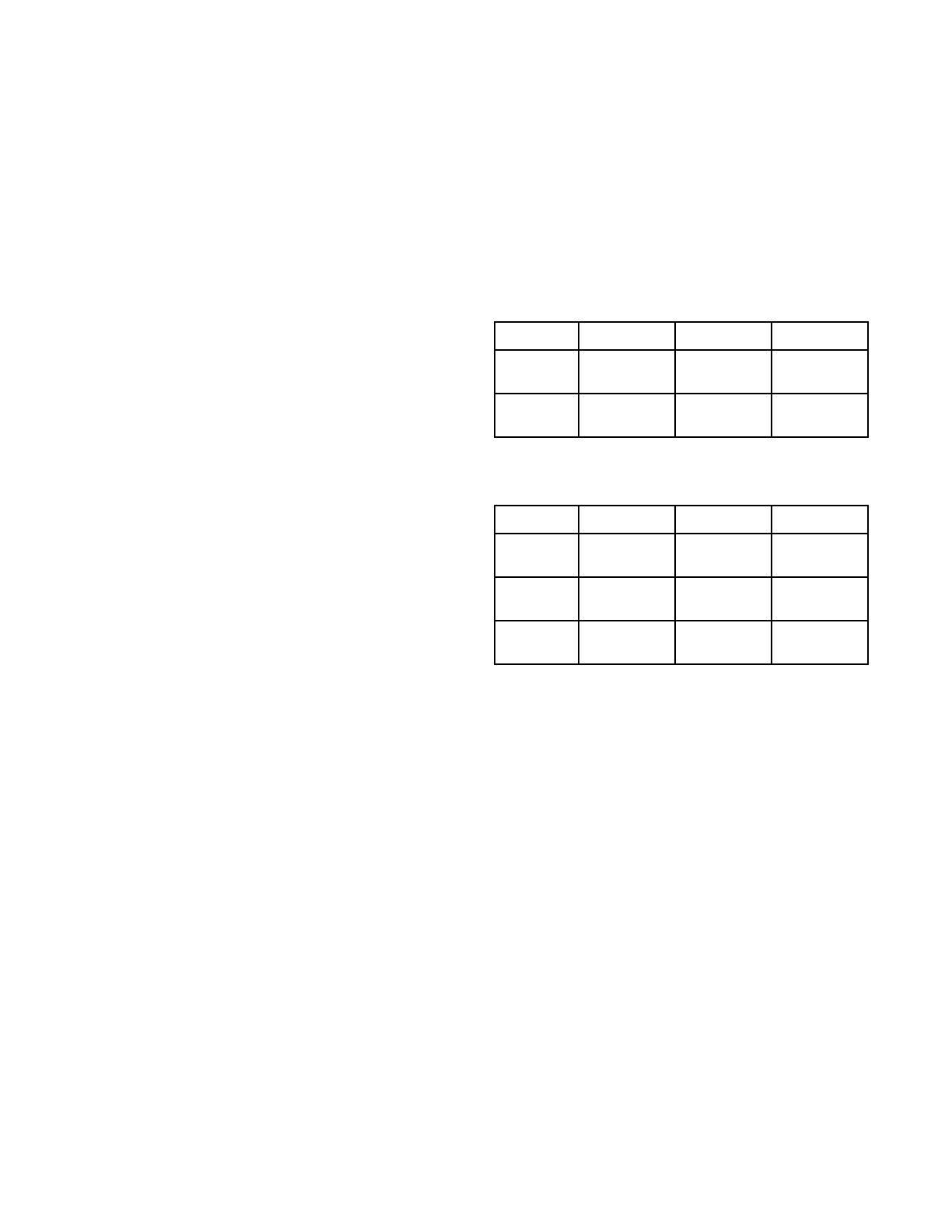
them for the dryer. The spin speeds and duration of
this final high spin cycle are determined by the type of
wash cycle selected (refer to Table 1 or Table 2).
NOTE: Washer may not reach 1000 RPM because
of an out-of-balance condition. Control may limit
speed to 850, 650 or 500 RPM depending on severity
of out-of-balance condition.
Models Through Serial No. 0911014602
Regular Perm Press Delicate
650
RPM 3
minutes 4
minutes 4
minutes
1000
RPM 3
minutes 2
minutes 0
minutes
Table 1
Models Starting Serial No. 0911014603
Regular Perm Press Delicate
500
RPM 0
minutes 0
minutes 4
minutes
650
RPM 3
minutes 6
minutes 0
minutes
1000
RPM 3
minutes 0
minutes 0
minutes
Table 2
803404 9
© Copyright, Alliance Laundry Systems LLC – DO NOT COPY or TRANSMIT
Introduction
Technical (Washer)
The basic operational system of this washer consists of
the electronic control, the inverter control, pressure
switch, water valves, electric pump (or drain valve)
and A.C. motor.
The electronic control performs all control and timing
functions like the timer in a topload washer. The
electronic control sends simple speed and output
commands to the inverter control via serial
communication. The electronic control powers the
door lock, pump (or drain valve) and the inverter
control.
The inverter control powers the A.C. motor and
performs all motor control functions. The inverter
control also powers the water and dispenser valves and
passes the pressure switch status to the electronic
control. The inverter control is powered through the
door switch, door lock switch and electronic control.
The inverter control also alerts the electronic control to
any errors in the motor.
The inverter control uses a speed sensor on the motor
to measure the drum RPM. Before entering any spin
step the inverter control measures the RPM of the
drum to sense out-of-balance. The inverter control will
try to redistribute the clothes if an out-of-balance
condition exists the inverter control will limit the spin
speed to several speeds depending on the severity of
the out-of-balance condition. If the out-of-balance
condition is severe enough the inverter control will
limit speed to 90 RPM and will not spin.
NOTE: An additional out-of-balance switch is used
to detect any out-of-balance condition during spins.
If this switch opens during a spin step, the inverter
control immediately stops and then restarts the
spin.
10 803404
© Copyright, Alliance Laundry Systems LLC – DO NOT COPY or TRANSMIT
Section 3
General Troubleshooting
1. Troubleshooting Coin Drop
a. Non-Electronic Coin Drops:
When coin is placed into coin slot, the coin
should roll down drop and be heard dropping into
coin vault. If coin does not fall into coin vault or
if coin drop sensor does not register that coin has
been entered, follow troubleshooting instructions
on following page. Refer to Figure 1 for path that
coin follows when working properly.
IMPORTANT: Never use oil to correct coin drop
problems. Oil residue will prevent coins from rolling
properly.
IMPORTANT: Do not bend or damage mechanical
parts within coin drop.
To reduce the risk of electric shock, fire, explosion, serious injury or death:
Disconnect all electric power to the machine and accessories before servicing.
Close gas shut-off valve to gas dryer before servicing.
Never start machine with any guards/panels removed.
Whenever ground wires are removed during servicing, these ground wires must be
reconnected to ensure that the machine is properly grounded.
Washer motor not grounded! Disconnect electric power before servicing motor.
W502
WARNING
Figure 1
DRY2B
Additional coins
following path to
sensor
Coin Drop
Sensor
Coin in
Coin Slot
803404 11
© Copyright, Alliance Laundry Systems LLC – DO NOT COPY or TRANSMIT
General Troubleshooting
Troubleshooting Coin Drop
Is
machine level?
(Machines that aren't
level may prevent coins from
following through required
check stages
of drop.)
No
Yes
No
Refer to wiring
diagram for
proper connections.
Yes
No
Yes
SWD1714S
Is proper
electrical power
supplied to coin drop?
(Incorrect electrical connection
may prevent coins from
registering in
coin drop.)
Is coin drop
clean? (Residue or
lint build-up may prevent
coins from following through
required check stages
of drop.)
Refer to
Adjustments section
for instructions on cleaning
drop.
Replace
coin drop sensor.
Refer to
Installation Instructions
for instructions
on leveling machine.
Do coins
fall freely
through drop?
No
Replace
coin drop.
Yes
12 803404
© Copyright, Alliance Laundry Systems LLC – DO NOT COPY or TRANSMIT
General Troubleshooting
b. Electronic Coin Drops:
If coin drop is not accepting coins, perform the
following:
(1) Clean coin drop. Refer to Paragraph 55.
(2) On electronic coin drops with an old-style
tension spring (shown in Figure 2 and
Figure 4), test and replace tension spring
using the following instructions.
Remove Coin Drop From Machine
(1) Disconnect electrical power to machine and
drop.
(2) Remove coin drop from machine.
Test Tension Spring
(1) Push coin return button to open and close
coin drop cover to clear possible coin jams.
Refer to Figure 2.
(2) Manually hold down coin drop cover and
insert coin. Refer to Figure 3.
(3) If coin drop now operates properly, replace
tension spring using instructions on
following pages.
Replace Tension Spring
(1) Move tension spring downward until cover
catch is free. Refer to Figure 4.
(2) Open cover for coin drop.
(3) Place a small flathead screwdriver under
right side of tension spring and lift up.
Refer to Figure 5.
(4) Use screwdriver to move spring
approximately 3 mm to left.
(5) Lift spring over left tab. Refer to Figure 5.
Figure 2
Figure 3
MIX7B
Coin Drop
Cover
Coin Return
Button
Tension
Spring
MIX6B
Coin Drop
Cover
Figure 4
Figure 5
DRY2088N
Cover Catch
Tension
Spring
MIX2B
803404 13
© Copyright, Alliance Laundry Systems LLC – DO NOT COPY or TRANSMIT
General Troubleshooting
(6) Rotate spring clockwise, 40 to 60 degrees,
until it is free from right tabs. Refer to
Figure 6.
(7) Use screwdriver to remove spring from
center tab. Refer to Figure 6.
(8) Lift spring, with attached clip, off drop.
(9) Remove clip from spring. Refer to
Figure 7.
(10) Attach clip to new tension spring, Part No.
209/00598/02.
(11) Place clip, installed on spring, in slot on
coin drop. Refer to Figure 8.
(12) Use a small flathead screwdriver to push
spring under center tab. Refer to Figure 9.
(13) Lift spring gently to place in position under
left tab.
(14) Push spring to right until it snaps into
position. Refer to Figure 5.
(15) Close coin drop cover.
(16) Move tension spring over cover catch.
Refer to Figure 4.
Reinstall Coin Drop Into Machine
(1) Reinstall coin drop into machine.
(2) Reconnect electrical power to machine and
drop.
(3) Add a coin to drop to verify that coin drop
is operating properly and that electrical
connection is working properly.
Figure 6
Figure 7
Figure 8
MIX3B
Tabs
Center Tab
MIX4B
Clip
MIX8B
Slot
Figure 9
MIX5B
Small Flat
Screwdriver
Center
Tab
Left Tab
14 803404
© Copyright, Alliance Laundry Systems LLC – DO NOT COPY or TRANSMIT
General Troubleshooting
2. Washer Motor Circuit
3. Troubleshooting Knocking Noise
If a frontload washer produces a noise similar to a
knock on a door, it might be due to a flat spot on
the belt. The knocking sound is made when the
flat spot hits the pulley. The knocking may occur
during a pulse spin and fade after reaching a
higher RPM.
To correct this condition, replace the belt.
To reduce the risk of electric shock, fire, explosion, serious injury or death:
Disconnect all electric power to the machine and accessories before servicing.
Close gas shut-off valve to gas dryer before servicing.
Never start machine with any guards/panels removed.
Whenever ground wires are removed during servicing, these ground wires must be
reconnected to ensure that the machine is properly grounded.
Washer motor not grounded! Disconnect electric power before servicing motor.
W502
WARNING
Windings
Tach. Circuit
White
Gray
Red
Red
Red
54321
Resistance Values:
Tachometer Circuit:
Terminals 4–5
Approx. 115 ohms
Windings:
Terminals 1–2, 2–3, 1-3
Approx. 4.5 ohms
803404 15
© Copyright, Alliance Laundry Systems LLC – DO NOT COPY or TRANSMIT
General Troubleshooting
To reduce the risk of electric shock, fire, explosion, serious injury or death:
Disconnect all electric power to the machine and accessories before servicing.
Close gas shut-off valve to gas dryer before servicing.
Never start machine with any guards/panels removed.
Whenever ground wires are removed during servicing, these ground wires must be
reconnected to ensure that the machine is properly grounded.
Washer motor not grounded! Disconnect electric power before servicing motor.
W502
WARNING
4. No Spin Due to Out-of-Balance Switch Wiring Problem Starting Serial
Nos. Beginning 0307
A “no spin” condition could be the result of an open circuit in the wire harness or out-of-balance switch. First, check
that the harness is still connected to the out-of-balance switch. The out-of-balance switch is a normally closed
switch. (continued)
Figure 10
Wire Clamp
First Section
of Tape 4.5 In.
(11.43 cm)
From End of
Terminals
Third Section
of Tape 14 In.
(35.56 cm)
From End of
Terminals
Wire Tie
FLW1842B
45 degrees
Cut Off
Broken
Wires Here
16 803404
© Copyright, Alliance Laundry Systems LLC – DO NOT COPY or TRANSMIT
General Troubleshooting
To reduce the risk of electric shock, fire, explosion, serious injury or death:
Disconnect all electric power to the machine and accessories before servicing.
Close gas shut-off valve to gas dryer before servicing.
Never start machine with any guards/panels removed.
Whenever ground wires are removed during servicing, these ground wires must be
reconnected to ensure that the machine is properly grounded.
Washer motor not grounded! Disconnect electric power before servicing motor.
W502
WARNING
If broken wires are found at the out-of-balance switch
wire support, cut off portion of wires as shown in
Figure 10 and add new UL approved terminals.
a. To test the electrical circuit, disconnect
electrical power to the washer.
b. Remove the “H1” connector from the inverter
control assembly.
c. Use an Ohm meter to check the black/white to
violet/white wires. Circuit should read closed.
An open reading indicates a bad switch or
wire harness problem.
d. Flex the harness at the plastic wire clamp and
test continuity. If the base wire harness has an
open circuit it MUST be replaced or the
broken wires must be repaired with UL
approved terminals.
e. After replacing or repairing the wire harness,
wrap electrical tape around wires in two
locations as indicated below and in Figure 10.
Then secure the harness wires to the original
factory locations using clamp and wire tie.
Refer to Figure 10.
(1) The plastic wire clamp should be angled
toward the switch at 45 degrees.
(2) The clamp should wrap around the first
section of tape on the harness, which should
be placed approximately 4.5 inches (11.43
cm) from end of terminals.
(3) The harness should be secured to the
inverter control shield with a wire tie.
(4) The tie should wrap around the third section
of tape on the harness, which should be
placed approximately 14 inches (35.56 cm)
from end of terminals. Refer to Figure 10.
5. Troubleshooting LEDs on
Washer Inverter Controls
Starting Machine Serial No.
0911014603
There are three LEDs on the control to assist with
troubleshooting (refer to Figure 11):
Green LED on constant = 5VDC power
supply present
Green LED flashing one second on/one
second off = inverter control power up
Red LED flashing four times/second =
inverter control is communicating with
front end control
6. No Spin (Washer)
A no spin condition is not caused by intermittent
operation of the motor or motor control (inverter
assembly). DO NOT replace these components for no
spin complaints if the unit passes the following
procedure:
Figure 11
FLW1844B
LEDs
803404 17
© Copyright, Alliance Laundry Systems LLC – DO NOT COPY or TRANSMIT
General Troubleshooting
To reduce the risk of electric shock, fire, explosion, serious injury or death:
Disconnect all electric power to the machine and accessories before servicing.
Close gas shut-off valve to gas dryer before servicing.
Never start machine with any guards/panels removed.
Whenever ground wires are removed during servicing, these ground wires must be
reconnected to ensure that the machine is properly grounded.
Washer motor not grounded! Disconnect electric power before servicing motor.
W502
WARNING
6. No Spin (continued)
No spin.
FLW1789S
Allow unit to go
through complete
final spin cycle.
Does unit spin at
high speed?
Motor and
motor control
board are
operating
properly. Do
not replace
them.
Yes
With no load, rapid
advance to final spin
or select spin only
cycle. Close door
and start washer.
BEFORE replacing
the motor control
board, conduct the
following tests.
No
Is pressure
switch or
pressure
switch wiring
inoperative?
Is load
out-of-
balance? Unit makes three
attempts to re-
balance out-of-
balance loads. If all
attempts fail, final
high speed spin is
aborted. ONLY
proper loading can
correct problem.
Yes
Is there a slow
drain, clogged
pump or
oversudsing
condition? Pressure switch
must register an
"empty" condition
before unit will
enter spin. Clear
drain or pump.
Yes
Replace switch
and/or wiring.
No
No Does unit
spin now?
No
Check for broken out-of-
balance switch wires.
Refer to
No Spin Due to
Out-of-Balance Switch
Wiring Problem Starting
Serial Nos. Beginning
0307
paragraph.
Yes
18 803404
© Copyright, Alliance Laundry Systems LLC – DO NOT COPY or TRANSMIT
Section 4
Dryer Troubleshooting
IMPORTANT: Refer to wiring diagram for aid in testing dryer components.
To reduce the risk of electric shock, fire, explosion, serious injury or death:
Disconnect all electric power to the machine and accessories before servicing.
Close gas shut-off valve to gas dryer before servicing.
Never start machine with any guards/panels removed.
Whenever ground wires are removed during servicing, these ground wires must be
reconnected to ensure that the machine is properly grounded.
Washer motor not grounded! Disconnect electric power before servicing motor.
W502
WARNING
  • Page 1 1
  • Page 2 2
  • Page 3 3
  • Page 4 4
  • Page 5 5
  • Page 6 6
  • Page 7 7
  • Page 8 8
  • Page 9 9
  • Page 10 10
  • Page 11 11
  • Page 12 12
  • Page 13 13
  • Page 14 14
  • Page 15 15
  • Page 16 16
  • Page 17 17
  • Page 18 18
  • Page 19 19
  • Page 20 20
  • Page 21 21
  • Page 22 22
  • Page 23 23
  • Page 24 24
  • Page 25 25
  • Page 26 26
  • Page 27 27
  • Page 28 28
  • Page 29 29
  • Page 30 30
  • Page 31 31
  • Page 32 32
  • Page 33 33
  • Page 34 34
  • Page 35 35
  • Page 36 36
  • Page 37 37
  • Page 38 38
  • Page 39 39
  • Page 40 40
  • Page 41 41
  • Page 42 42
  • Page 43 43
  • Page 44 44
  • Page 45 45
  • Page 46 46
  • Page 47 47
  • Page 48 48
  • Page 49 49
  • Page 50 50
  • Page 51 51
  • Page 52 52
  • Page 53 53
  • Page 54 54
  • Page 55 55
  • Page 56 56
  • Page 57 57
  • Page 58 58
  • Page 59 59
  • Page 60 60
  • Page 61 61
  • Page 62 62
  • Page 63 63
  • Page 64 64
  • Page 65 65
  • Page 66 66
  • Page 67 67
  • Page 68 68
  • Page 69 69
  • Page 70 70
  • Page 71 71
  • Page 72 72
  • Page 73 73
  • Page 74 74
  • Page 75 75
  • Page 76 76
  • Page 77 77
  • Page 78 78
  • Page 79 79
  • Page 80 80
  • Page 81 81
  • Page 82 82
  • Page 83 83
  • Page 84 84
  • Page 85 85
  • Page 86 86
  • Page 87 87
  • Page 88 88
  • Page 89 89
  • Page 90 90
  • Page 91 91
  • Page 92 92
  • Page 93 93
  • Page 94 94
  • Page 95 95
  • Page 96 96
  • Page 97 97
  • Page 98 98
  • Page 99 99
  • Page 100 100

Alliance Laundry Systems STGLYFSP111TWNA User manual

Category
Washer dryers
Type
User manual

Ask a question and I''ll find the answer in the document

Finding information in a document is now easier with AI