Smeg KMN75X is a high-quality extractor hood designed to efficiently eliminate kitchen odors and fumes. With its sleek design and powerful motor, it offers an array of features to enhance your cooking experience. The hood is equipped with three speed settings, allowing you to adjust the extraction power based on your cooking needs. Additionally, it features a built-in light to illuminate your cooking area, ensuring better visibility while you cook.
Smeg KMN75X is a high-quality extractor hood designed to efficiently eliminate kitchen odors and fumes. With its sleek design and powerful motor, it offers an array of features to enhance your cooking experience. The hood is equipped with three speed settings, allowing you to adjust the extraction power based on your cooking needs. Additionally, it features a built-in light to illuminate your cooking area, ensuring better visibility while you cook.


-
 1
1
-
 2
2
-
 3
3
-
 4
4
-
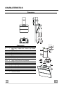 5
5
-
 6
6
-
 7
7
-
 8
8
-
 9
9
-
 10
10
-
 11
11
-
 12
12


Smeg KMN75X is a high-quality extractor hood designed to efficiently eliminate kitchen odors and fumes. With its sleek design and powerful motor, it offers an array of features to enhance your cooking experience. The hood is equipped with three speed settings, allowing you to adjust the extraction power based on your cooking needs. Additionally, it features a built-in light to illuminate your cooking area, ensuring better visibility while you cook.
Ask a question and I''ll find the answer in the document
Finding information in a document is now easier with AI
Related papers
Other documents
-
Falcon L 540 720 User manual
-
Rangemaster L 540 720 User manual
-
Zanussi ZHC66540XA User manual
-
LG DC9101S Owner's manual
-
LG DC9121GAU Owner's manual
-
 Ideal-Zanussi IZHC900X User manual
-
LG DC6121G Owner's manual
-
Electrolux EFC9500X/T User manual
-
-
Juno-Electrolux JDK9582E User manual
