Recessed Mounting
NE-242 Models Not Available for Recessed Mounting
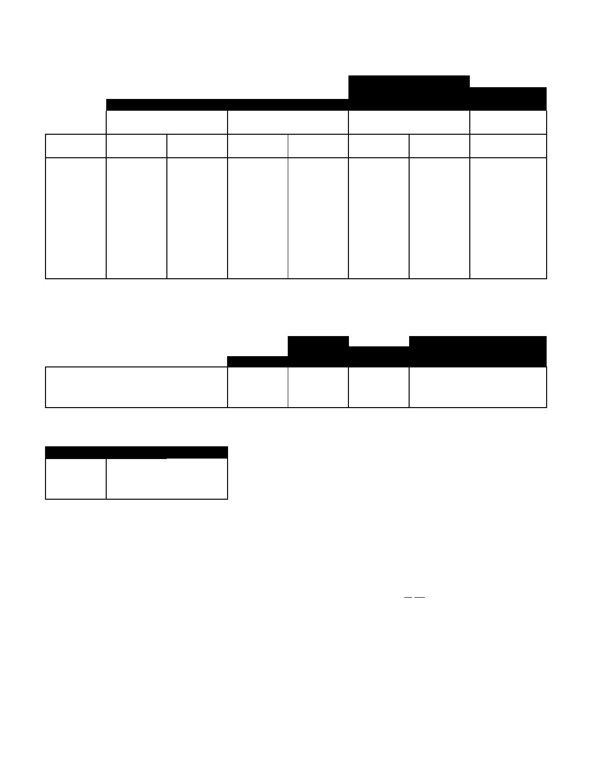
1. Determine desired ironing board height using the chart below. Care should be taken to ensure the unit will be mounted at the desired ironin
board height
A-42
E-342 with Optional Swivel E-342
A-46 A-46 with Optional Swivel NE-342 with Optional Swivel NE-342
Ironing Ironing Ironing Ironing
Board Height Board Height Board Height Board Height
Opening Height Regular Adjusted Regular Adjusted Regular Adjusted Regular
Above Floor Position Position Position Position Position Position Position
30" 37"
29" 36"
28" 35" 39" 35"
27" 34" 38" 34"
26" 33" 37" 33"
25" 32" 36"
24" 37" 41" 31" 35"
23" 37" 33" 36" 40"
22" 36" 32" 35" 39"
21" 35" 31" 34" 38"
20" 34" 30" 33" 37"
19" 33" 29"
2. Using a stud finder, locate the wall studs to be used for mounting.
3. Locate the existing wiring or other utilities in the wall to prevent drilling into or severing a wire or other utility during installatio
4. Determine the desired location has adequate clearance for ironing. Door opens approximately 180°. Allow at least 16" from side of cabin
for door to swing open
A-46 with A-42
Optional E-342 E-342 with Optional Swivel
A-46 Swivel NE-342 NE-342 with Optional Swivel
Distance from Wall to Tip of Ironing Board 45" 50 1/4" 41" 46 7/8"
Swivel Clearance from Cutout Opening of Cabinet N/A 16 7/8" N/A 14 5/8"
Distance from Wall in Full Swivel Position N/A 32 1/4" N/A 32 5/8"
Standing Area Clearance ** 24" 24" 24" 24"
** The recommended distance from the side of the ironing board where the user will typically stand to ensure adequate space for ironin
5. Cut an opening in the wall per the opening sizes shown belo
Model Opening Size
A-46 14 1/4" x 59 7/8" x 3 7/8"
A-42 14 1/4" x 47 1/8" x 3 7/8"
E-342 14 1/4" x 47 1/8" x 3 7/8"
NE-342 14 1/4" x 47 1/8" x 3 7/8"
6.
ttach 2" x 4" cross support cleat between the studs, level with the bottom of the openin
7. The cabinet will be attached to studs using four screws, one in each side at the top of cabinet and one in each side at bottom
cabinet. Using a 1/8" drill bit, pre-drill pilot holes approximately 14" from the top of the cabinet and 1 1/2" from the back of the cabinet. F
models without a swivel, pre-drill pilot hole approximately 14" from the bottom and 1 1/2" from the back of the cabinet. For models with
swivel board, complete Steps 8, 9, and 10 before pre-drilling pilot holes for bottom locatio
o
e:
an e
ec
r
ca
mo
e
s
e
ng
ns
a
e
,
e
emporary remova
o
e e
ec
r
ca
w
reway may
e
e
p
u
o comp
e
e
s s
ep.
Reinstall electrical wireway after cabinet is attached to studs.
8.
ns
a
ng an e
ec
r
ca
mo
e
, p
ease rev
ew
ec
r
ca
ns
ruc
ons now.
ns
a
ng a non-e
ec
r
ca
mo
e
no
ns
a
your own
electrical outlet inside cabinet. Warranty voided if independent electrical outlet installed within non-electrical ironing center cabinet.
9. Begin installation by carefully lifting ironing center into the wall openin
10. Plumb and level the cabinet. Shim to fit
11. For models with swivels, continue with Step 12. For models without swivels, attach cabinet to studs using the four pre-drilled holes
with four #10 x 1 1/2" screws. Once complete, continue to Step 13.
12.
ttach cabinet to studs using the two pre-drilled holes and two #10 x 1 1/2" screws for the top installation. Locate the side ironing boar
brackets that are secured to the cabinet with three screws each. Remove the top screw only from each side bracket. Use this locatio
to pre-drill pilot holes for bottom installation location. Pre-drill a pilot hole through top hole in each bracket into stud. Finish attaching
cabinet into studs using the #14 x 2 1/2" screws for the just completed two pre-drilled holes in each side bracke
13. Decorative trim may be added to cover any irregular cuts when making opening for ironing cente


