Asco Series 195 Solenoid Valve ATEX 94/9/EC Owner's manual
- Type
- Owner's manual

2 3
3835100-1
INSTALLATION AND MAINTENANCE INSTRUCTIONS
GB
Solenoid valve for use in explosive atmospheres according to ATEX 94/9/EC, intrinsically safe
II 2 G Ex ia IIC T4 - II 2 G Ex ia IIB T4 - II 2 G Ex ia IIC T6 - II 2 G Ex ia IIB T6
(Series 195)
3835100-1
• Ingress protection rating according to EN 60529 : IP65
Special conditions for safe use:
ASCO components are intended to be used only within the
technical characteristics specifi ed on the nameplate or in the
documentation. Changes to the equipment are only allowed af-
ter consulting the manufacturer or its representative.
This solenoid valve which is equipped with an Ex ia rated sole-
noid operator is designed to be installed in potentially explosive
atmospheres caused by gases, vapours or mists of group II
(category 2 G).
The surface temperature classifi cation is T6 - T4 and depends
on the power rating, ambient temperature and assembly of the
product.
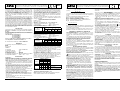
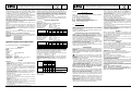
ELECTRICAL CHARACTERISTICS
DC coils (=)
type (series) 195
Marquing: II 2 G Ex ia IIC T4 and II 2 G Ex ia IIC T6 :
Nominal supply voltage : Umax. = 28 V,
Max. current consumption : Imax. = 115 mA (24 V)
Max. dissipated power : Pmax. = 1,6 W
Insulation class F (155°C) 100% E.D.
classifi cation
Pn
safety parameters
U
i
= (DC)
I
I
P
I
L
I
C
I
(W)
(V) (mA) (W)
(μF)
(mH)
II 2 G Ex ia IIC T4 0,5
28 115 1,6 0 0
II 2 G Ex ia IIC T6 0,5
28 115 1,6 0 0
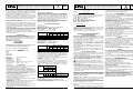
Marquing: II 2 G Ex ia IIB T4 and II 2 G Ex ia IIB T6 :
Nominal supply voltage : Umax. = 32 V,
Max. current consumption : Imax. = 195 mA (24 V)
Max. dissipated power : Pmax. = 1,6 W
Insulation class F (155°C) 100% E.D.
classifi cation
Pn
safety parameters
U
i
= (DC)
I
I
P
I
L
I
C
I
(W)
(V) (mA) (W)
(μF)
(mH)
II 2 G Ex ia IIB T4 0,5
32 195 1,6 0 0
II 2 G Ex ia IIB T6 0,5
32 195 1,6 0 0
The solenoid valve type 195 must be supplied with power from
a voltage barrier certifi ed for use in potentially explosive atmos-
pheres of groups IIC, IIB or IIA and having an output circuit that
is rated intrinsically safe. The valve-and-barrier combination
must be compatible in terms of intrinsic safety.
The voltage barrier for the equipment must have the following
maximum characteristics:
Uo = 28 V ; Io = 115 mA ; Po = 1,6W or
Uo = 32 V ; Io = 195 mA ; Po = 1,6W
Since the two parameters Ci and Li of the equipment are both
equal to zero, the maximum output characteristics Co and Lo
of the voltage barrier must exceed the effective values of C and
L of the connecting cable used.
Selecting the barrier and making the interconnections are at the
user’s responsibility.
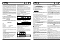
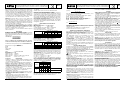
Pn
(watt)
max. ambient °C
(1)
surface temperature
T6
85°C
T5
100°C
T4
135°C
IIC IIB IIC IIB IIC
IIB
insulation class F (155°C) 100% E.D.
(2)
1,6
50 50 - - 85 85
max. ambient °C
70 70 - - 80 80 max. fl uid °C
Check the power compatibility with the selected product.
Minimum ambient temperature: -40°C
This temperature may be limited by the operating temperature
rating of the pilot valve or spool valve.
Calculation of operating conditions:
I
l
(mA) =
[ V
s
- 1 ] x 1000
(R
c
+ R
l
+ R
b
)
This value (I
l
) as well as the maximum current of the barrier/
GENERAL
These Installation and Maintenance Instructions are for series
195 solenoid valves (II 2 G Ex ia IIC T4, II 2 G Ex ia IIB T4,
II 2 G Ex ia IIC T6, II 2 G Ex ia IIB T6) with mounting pad to ISO
15218 [CNOMO size 30 (06.05.80)].
In case of an assembly to or installation on another valve, the
Installation and Maintenance Instructions and Declarations of
Conformity relating to the specifi c valve must be taken into ac-
count for assembling and putting the solenoid valve into opera-
tion.
Malfunction, damage or injury may occur if these instructions
are not followed.
This component is not a safety accessory, it is intended only for
the compliant use either as an individual component or incor-
porated in apparatus, machinery and installations.
All assembly, operation, use, and maintenance must be per-
formed by qualifi ed, authorised personnel.
Personnel working with the components must be familiar with
the safety regulations and requirements relating to the com-
ponents, apparatus, machinery and electrical installations (for
valves, solenoid valves, electronic control equipment, air serv-
ice equipment). In case of problems, please contact ASCO or
one of its authorised representatives.
DESCRIPTION
The solenoid valve type195 is intended for fl uid control.
Essential Health and Safety Requirements:
This solenoid valve (type 195) is designed in accordance
with Annex II of European Directive 94/9/EC and standards
EN 60079-0 and EN 60079-11.
Classifi cation II 2 G Ex ia IIC T4
II 2 G Ex ia IIB T4
II 2 G Ex ia IIC T6
II 2 G Ex ia IIB T6
The certifi cates of conformity in compliance with these
standards are available at www.asconumatics.eu
EC type examination certifi cate no.: LCIE 08 ATEX 6083
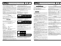
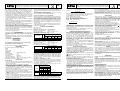
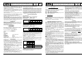
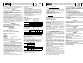
MARKING
The marking includes the following information:
ASCO
BP17
28111 LUCE
FRANCE
Marking : LCIE 08 ATEX 6083
Type designation : 195
Year of manufacture : 20..
Serial number : xxxxxxxx
Specifi c marking : q II 2 G
Additional marking : Ex ia IIC T4, IIB T4 or IIC T6, IIB T6
Ambient/operating : Tamb. = -40°C , + 50°C
INSTALLATION
Preparation:
• Check the preliminary storage conditions required for the com-
ponent. They must be in accordance with the product’s speci-
fi cations.
• Carefully remove the components from their packaging.
• Power off and depressurise the apparatus, machinery, or
installation designed to receive the component. Stipulate
power off and depressurisation requirements to guard against
any unauthorised intervention.
• Make sure that the unit, its components, and their environ-
ment are clean, and protect them against deterioration.
• In order to protect the equipment, install an adequate strainer
or fi lter upstream from and as close as possible to the compo-
nent.
• Do not modify the device.
• Make sure the solenoid valve’s mating surface is clean to pre-
vent damage to the seals.
• Make sure that the fl uid is compatible with the materials it con-
tacts.
Fluids used: air or neutral gas, fi ltered (50µm.)
Allowable fl uid temperature: -40°C to +70°C
This temperature may be limited by the operating tempera-
ture rating of the pilot valve or spool valve. Dew point -20°C.
• The solenoid valve must be installed in a non-corrosive, air or
liquid environment.
3835100-A
Availability, design and specifi cations are subject to change without notice. All rights reserved.
INSTALLATION AND MAINTENANCE INSTRUCTIONS
GB
Solenoid valve for use in explosive atmospheres according to ATEX 94/9/EC, intrinsically safe
II 2 G Ex ia IIC T4 - II 2 G Ex ia IIB T4 - II 2 G Ex ia IIC T6 - II 2 G Ex ia IIB T6
(Series 195)
interface (if it is non-linear) must exceed 37 mA.
I
l
(mA) Minimum supply current for the product
R
b
(Ω) Max. barrier resistance
T
a
(°C) Max. ambient temperature
R
l
(Ω) Max. resistance of connecting cables
V
s
(V) Min. no-load voltage of barrier/interface
R
c
(Ω) Max. coil resistance:
R
c
=
297 (T
a
+ 234 + 10)
254
Depending on the ambient temperature/power rating, a heat
resistant cable suitable for the temperature indicated on the
coil must be used.
The installer is required to proceed in accordance with European
Directive 1999/92/EC and associated standards.
COMPATIBLE BARRIERS AND INTERFACES
These 24 V DC solenoid valves are compatible with the barriers
given in the table on page 26.
These barriers and interfaces allow to feed the intrinsically safe
solenoid valves located in explosive areas.
This equipment must be ordered from its respective manu-
facturers specifying that they are intended to feed intrinsically
safe solenoid valves 195, ll 2 G Ex ia llC T4 / ll 2 G Ex ia llB T4
/ ll 2 G Ex ia llC T6
/ ll 2 G Ex ia llB T6.
According to the zones and following the country legislation,
apply the certifi cation procedure relative to the association of
IS products.
ASCO declines any responsibility for the use of products from
other suppliers and the possible modifi cations of their charac-
teristics.
ELECTRICAL INSTALLATION
The solenoid valve must be installed under the responsibility
of the company operating the industrial site. The system as a
whole must conform to standard EN60079-14.
Before starting any work, turn off the electrical current to
power off the components.
All screw terminals must be tightened to the appropriate torque
prior to operation.
!
Install the cable so that there is no tension on the valve body.
When connecting the cables to the series 195 solenoid valves,
fi rst place all the cables in the cable trays or wireways before
attaching them to the connectors.
The electrical connection is made by
• Detachable connector with an IP65 protection (when properly
mounted). Tighten each wire on the connector’s terminal to
the specifi ed torque. The tightening torque for the cable gland
is 2,5 ±0,1 N.m to ensure tightness to IP65.
Spade plug connector, ISO 4400/EN 175301-803, form A
(cable entry dia. 6 to 8 mm).
The connector delivered with each product MUST be
mounted. Any other assembly/installation will invalidate
the approval. Do not mount or remove the connector while
the power is ON.
Operation: Before pressurising the system, fi rst carry out an
electrical test. Apply power to the coil several times and listen
for the metallic «click» indicating the solenoid operator is work-
ing.
Personnel working with the components must be familiar with
electric controls, such as redundancies and feedback (electron-
ic controls), where applicable.
Use: The coils are designed for continuous operation and may
therefore become hot.
If the solenoid valve is easily accessible, provide for means of
protection to prevent accidental contact that may cause burns.
To avoid overheating, do not operate the solenoid valve in a
confi ned space without suffi cient ventilation.
CONNECTION
• Connect all ports that may come in contact with fl uids. Mount
in accordance with the ISO 15218 (CNOMO size 30) mount-
ing pad pattern. Make sure to check that all seals are placed
on the mounting pad.
Pre-install the 2 CM4 x 35 screws alternately and evenly up to
a tightening torque of 0,3/0,5 Nm, and then tighten them to a
tightening torque of 1 Nm
±0,2
(E).
• Clean the conduits that will connect to the component.
• Be sure to observe the direction of fl ow of the fl uid.
• Use only the provided connection possibilities.
• Ensure that no foreign matter enters the circuit, in particular
when making the connection leakproof.
• The manual override, which is indicated by the symbol (
),
allows you to operate the valve without electrical power.
• Be sure to observe the allowed bend radius for tubing; do not
restrict the ports for fl uid circulation.
• Tubes and connection elements must not exert any force,
torque, or strain on the product.
• Use appropriate tools and place assembly tools as close as
possible to the connection point.
• Be sure to observe the recommended torque when tightening
piping connections.
• Connections must be made to last.
CAUTION
Failure to stay within the electrical range of the coil rating will
result in damage to or premature failure of the coil. This will also
invalidate its approval for use in explosive atmospheres caused
by gases.
WARNING: Unauthorised personnel is not permitted to disas-
semble or remove the coil or connector assembly.
Take care not to damage the mating surfaces when disassembling
or re-assembling the connector/coil assembly/clip.
Wrong assembly will invalidate the approval.
OPERATION
To prevent the risk of personal injury or property damage, do
not touch the coil. The coil can become hot under normal op-
eration conditions. If the solenoid valve is easily accessible, the
installer must provide protection against accidental contact.
To prevent electrostatic hazard, clean coil surface with a damp
cloth only. Do not use solvents.
MAINTENANCE
CAUTION: Turn off electrical power before servicing.
Strictly follow all procedures recommended by European Direc-
tive 1999/92/EC and associated standards during maintenance.
There are no ATEX spare parts kits available.
The solenoid valve cannot be disassembled or adjusted.
Do not remove the coil from the pneumatic part of the solenoid
valve.
DISASSEMBLY/REASSEMBLY:
This operation must be carried out by suitably qualifi ed person-
nel.
Unscrew and remove the connector. Remove the plug (6) and
the coil.
Reassemble in the reverse order of disassembly (make sure to
observe the tightening torques (A..D)).
The solenoid valve and the assembly consisting of the seal and
the connector must be completely re-assembled for IP65 pro-
tection to be certifi ed.
Wrong assembly will invalidate the approval.
In case of replacement of parts by the user, the traceability
of the fi nal product cannot be guaranteed by ASCO and
must be ensured by the user.
Page is loading ...
Page is loading ...
Page is loading ...
Page is loading ...
Page is loading ...
Page is loading ...
Page is loading ...
Page is loading ...
Page is loading ...
Page is loading ...
Page is loading ...

26
CONNECTION
GB
RACCORDEMENT
FR
ANSCHLUSS
DE
RACORDAJE
ES
COLLEGAMENTO
IT
AANSLUITING
NL
ANSLUTNING
SE
TILKOBLING
NO
LIITÄNTÄ
FI
FORBINDELSE
DK
LIGAÇÃO
PT
ÓÕÍÄÅÓÇ
GR
PIPOJENÍ
CZ
PODCZENIE
PL
CSATLAKOZTATÁS
HU
RU
----
27
CONNECTION
GB
RACCORDEMENT
FR
ANSCHLUSS
DE
RACORDAJE
ES
COLLEGAMENTO
IT
AANSLUITING
NL
ANSLUTNING
SE
TILKOBLING
NO
LIITÄNTÄ
FI
FORBINDELSE
DK
LIGAÇÃO
PT
ÓÕÍÄÅÓÇ
GR
PIPOJENÍ
CZ
PODCZENIE
PL
CSATLAKOZTATÁS
HU
RU
----
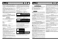
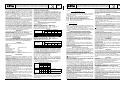
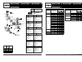
F
Rep. N.m Inch.Pounds
A 0,6 ±0,1 5,3 ±0,9
B 2,5 ±0,2 22 ±1,8
C 0,25 ±0,1 2,2 ±0,9
D 2 ±0,2 17,6 ±1,8
195
Ex ia
ATEX
4
C
4 x 90˚
B
E
2
3
6
5
1
Ø 8..10 mm
Ø 6..8 mm
A
(Pg 11p)
1
2
7
8
D
4 x 90˚
GB
Designation
FR
Désignation
1. Screw
2. Housing
3. Terminal block
4. Connector seal
5. Coil
6. Screw plug
7. Core tube
8. Screw
1. Vis
2. Boîtier
3. Support de bornier
4. Joint
5. Bobine
6.
Bouchon de serrage
7. Tube-culasse
8. Vis
DE
Bezeichnung
ES
Designación
1. Schraube
2. Gehäuse
3. Klemmenblock
4. Dichtung/Leitungsdose
5. Magnetspule
6. Schraubstopfen
7. Führungsrohr
8. Schraube
1. Tornillo
2. Caja
3. Soporte de bornero
4. Junta
5. Bobina
6. Tapón de apriete
7. Tubo culata
8. Tornillo
IT
Descrizione
NL
Aanduiding
1. Vite
2. Contenitore
3.
Supporto del blocco terminale
4. Guarnizione
5. Bobina
6. Dado di chiusura
7. Cannotto
8. Vite
1. Schroef
2. Huls
3. Steun voor klemmenbord
4. Pakking
5. Spoel
6. Plug met schroefdraadl
7. Plunjergang
8. Schroef
NO
BESKRIVELSE
SE
BESKRIVNING
1. Skrue
2. Koplingsboks
3. Terminalblokk
4. Koplingsboksens tetning
5. Spole
6. Skrueplugg
7. Kjernerør
8. Skrue
1. Skruv
2. Hölje
3. Anslutningsplint
4. Anslutningsförsegling
5. Spole
6.
Skruvpropp
7. Kärna rör
8. Skruv
FI
KUVAUS
DK
BESKRIVELSE
1. Ruuvi
2. Liitinkotelo
3. Kytkintaulun pidin
4. Tiiviste
5. Kela
6. Kierretulppa
7. Sisäletku
8. Ruuvi
1. Skrue
2. Hus
3. Holder til klemrække
4. O-ring
5. Spole
6. Skrueprop
7. Nippel
8. Skrue
PT
DESCRIÇÃO
GR
ÐÅÑÉÃÑÁÖÇ
1. Parafuso
2. Manga
3.
Suporte do conjunto de terminais
4. Anel
5. Bobina
6. Bujão de parafuso
7. Tubo central
8. Parafuso
1. Âßäá
2. ÈÞêç
3. ÓôÞñéîç èÞêçò
4. ÐáñÝìâõóìá
5. Ðçíßï
6. ÂéäùôÞ ôÜðá
7. ÐõñÞíáò
8. Âßäá
2
3
1
INTERFACES ZENER BARRIERS
manufacturer module type
II 2 G Ex ia
manufacturer module type
II 2 G Ex ia
T6 T4 T6 T4
IIB IIC IIB IIC IIB IIC IIB IIC
G.M. International
D1040Q-2
x
CEAG
SB-3729
xx
D1042Q-2
xx
SB-3728
x
MTL
MTL 3022
xx
MTL
MTL 728P
xx
MTL 5021
x
Pepperl
+
Fuchs
Z728
xxxx
Pepperl
+
Fuchs
KFD2-SD-Ex1.36
xx
Z728.H
xx
KFD2-SL2-Ex1
xx
Z728.CL
xxxx
KFD2-SL2-Ex1.B
xx
Stahl
9001/01-280-100-101
xx
KFD2-SL2-Ex1.LK
xx
9001/01-280-110-101
xxxx
KFD2-SL2-Ex2
xx
KFD2-SL2-Ex2.B
xx
KFD2-VD-Ex1.1560
xxxx
KCD0-SD-Ex1.1245
xx
KSD2-BO-Ex
xx
HIC2871
xx
LB-2102
xx
LB-2104
x
FB-2202
xx
FB-2204
x
Turck
MC72-41Ex-T/24VDC
xxxx
MC72-44Ex-T
xxxx
Siemens ET200IS double
xx
WAGO 750-535
xx
PR-electronics 5203B-F
xxxx
ASCO JOUCOMATIC SA
32 Av. Albert 1
er
- BP 312 - 92506 RUEIL Cedex - France
Tel. (33) 147.14.32.00 - Fax (33) 147.08.53.85 - http://www.asconumatics.eu
Page is loading ...
Page is loading ...
-
 1
1
-
 2
2
-
 3
3
-
 4
4
-
 5
5
-
 6
6
-
 7
7
-
 8
8
-
 9
9
-
 10
10
-
 11
11
-
 12
12
-
 13
13
-
 14
14
-
 15
15


Asco Series 195 Solenoid Valve ATEX 94/9/EC Owner's manual
- Type
- Owner's manual
Ask a question and I''ll find the answer in the document
Finding information in a document is now easier with AI
in other languages
- italiano: Asco Series 195 Solenoid Valve ATEX 94/9/EC Manuale del proprietario
- français: Asco Series 195 Solenoid Valve ATEX 94/9/EC Le manuel du propriétaire
- español: Asco Series 195 Solenoid Valve ATEX 94/9/EC El manual del propietario
- Deutsch: Asco Series 195 Solenoid Valve ATEX 94/9/EC Bedienungsanleitung
- Nederlands: Asco Series 195 Solenoid Valve ATEX 94/9/EC de handleiding
- português: Asco Series 195 Solenoid Valve ATEX 94/9/EC Manual do proprietário
- dansk: Asco Series 195 Solenoid Valve ATEX 94/9/EC Brugervejledning
- svenska: Asco Series 195 Solenoid Valve ATEX 94/9/EC Bruksanvisning
- suomi: Asco Series 195 Solenoid Valve ATEX 94/9/EC Omistajan opas
Related papers
-
Asco Series 302 Mini Solenoid Valve Owner's manual
-
-
-
-
-
-
Other documents
-
 LEDPRO 101510-2 Plaza Up and Down Outdoor Wall Lamp Installation guide
-
 LEDPRO COLD 5 DOWNLIGHT, DRIVER INKLUDERT, HVIT Installation guide
-
 LEDPRO BY NORLUX TANIA MINI S4 LAMPE, SVART Installation guide
-
 LEDPRO BY NORLUX TANIA MINI S1 LAMPE, HVIT Installation guide
-
 LEDPRO BY NORLUX TANIA MINI S2 LAMPE, SVART Installation guide
-
 LEDPRO BY NORLUX TANIA MINI S3 LAMPE, HVIT Installation guide
-
AVENTICS Series G3 NAMUR Input Module Owner's manual
-
-
-


