
WINDTUNNEL TM
UPRIGHT
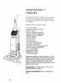
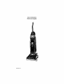
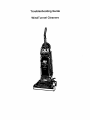
The WindTunnel TM series of uprights was first introduced
in mid 1997. Four deep wine colored models comprised
the line and all were similar in overall appearance like the
one in Figure 1.
Features included on the various models:
• 13" and 15" nozzles
• Embedded dirt finder (two models)
• Cords 31' and 35'
• Bag check indicator (three models)
• Agitator, replaceable roll sleeve type
• Headlight, one 12 volt 27313101
• Flat belt 38528033
• Hard bag enclosure
• One speed motor
• Stair cleaning handle
• Four position height adjustment
• Tool storage on the cleaner
Micro-filtration throw away bags Type "Y"
• Bag check indicator (three models)
• 4, 5 or 6 stage filtration
• Edge cleaning "Edgers"
• Rotating top cord hook
• 10' and 12' hose reach
Fig, 1
These cleaners operate on a clean air principle, i.e., where
the dirty air enters the bag or dirt receptacle before it goes
past the motor area. Since the same air is used to cool the
motor, it is extremely important that it be filtered ade-
quately to prevent dirt and dust from getting into the motor
and/or back into the room.
Basic operation of the clean air system in these units is
illustrated in Figure 2 on page 2.
Air fl0w in the WindTunnel is shown in Figure 2A on
page 2.
7/97

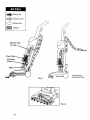
_ Dirty Air
ffff_ Filtered Air
Clean Air
Filters
Primary Filter
T.A. Bag
Secondary
Motor
Fig. 2
Air flow shown
using hose and tool.
Fig. 2A
7/97

II o
Fig. 3
Fig. 4
II
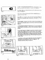
TYPE "Y" MICRO-FILTRATION throw away bags are Speci-
fied on all models as the primary (2 stage) filter Figure 3.
Secondary filters are located behind a grill in the bottom of the
bag cavity Figure 4.
They can be washed and reinstalled when completely dry or
replaced with new ones.
Final filters are located on the side of the bag housing Figure 5.
They too are washable and/or replaceable, and made in 1, 2 or 3
layers.
Nozzle height is adjusted on the front of the unit and ranges from
high, for very deep pile carpet, to bare floor on the lowest setting
Figure 6.
I
Fig. 5
L.
IIII iitlio,,.,,,.
BARE
FLOOR
j. 6
An Embedded Dirt _nder TM (F_DF) feature is on some models. The
conllOl circuit for this feature is directly wired and does not require a
battery.
Red and green lights (A in Figure 7) signal the user that the system is
working. The red light comes on when the cleaner is first energized
then goes off and the green one comes on to let the user know when to
begin cleaning. While cleaning, a red light indicates that embedded
dirt is being removed from the carpet. When the light turns green the
carpet is clean.
A sensitivity switch near the light allows the user to increase or
decrease the units sensitivity to dirt (B in Figure 8). "Hi"
increases sensitivity, "Reg" decreases it.
Fig. 7
Fig. 8
7197

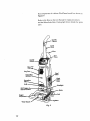
Key components of a deluxe WindTunnel model are shown in
Figure 9.
Refer to the Hoover Service Manual for repair procedures
and the Microfiche Parts Catalog light brown header for spare
parts.
On/Off
Control
Cord
Hook
Tool
o_off
Check Bag
Secondary
Final
Filter
Final
Filter
Door
Headlight
_elt
Wind Tunnel
Fig. 9
7197

Service Instructions
WindTunnel Uprights
Secvice Su_,'t 7/97

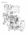
WindTunnel wlo EDF
HOLDER
HOSE_
EXT.
TOOLDOOR
RILL
BAGDOORGASKET
ANGLED
HOSE
CONNECTOR
ASSEMBLY _ i
BAGHOUSING
/
MOTOR
MOUNT
MOTOR
COVER
BAGDOOR

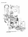
WindTunne| wlEDF
i
Ii
tl
II
If
:i
14. -- --
COMPONENT NAMES ARE THE SAME AS PAGE 149 A-2
EXCEPT THOSE LISTED
=RINTEDCIRCL
)ASSEMBLY

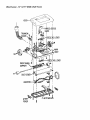
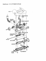
WindTunnel - 13" & 15" Width (Half Hood)
TRUNNION
_EA
SE
I t
BODY
I
FRONTWHEELl
SUPPORT_,
t_" DUCTCOVERJ
AE
ADJ.LEVER
%
PICKER

WindTunnel - 13" & 15" Width (Full Hood)
HOOD--
TRUNNION
COVER_
LEVER
BODY
l
FRONTWHEELI
SUPPORT
DUCTCOVER
BOTTOMPLATE
LITTER
PICKER

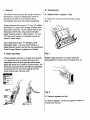
I. General
The WindTunnel cleaners are upright vacuums
that feature computer designed air vanes to
provide a powerful dual air stream which
dramatically improves dirt pickup capabilities.
These cleaners also come in 13" and 15" widths
and feature on board tool storage and fast easy
above floor cleaning. Some models feature the
Embedded Dirt Finder, Bag Check Indicator,
Edge Cleaning Edgers "Litter Pickers", 10' and
12' hose reach (upper end models include an
extra 20' reach hose).
All models feature type "Y" allergen top fill
disposable bags. Low end units include a 4
stage filtration system and as the line progresses
5 and 6 stage filtration systems are utilized.
II. Basic Operation
These cleaners operate on a clean air principle,
i.e., where the dirty air enters the bag or dirt
receptacle before itgoes past the motor area.
Since the same air is used to cool the motor, it is
extremely important that it be filtered adequately
to prevent dirt and dust from getting into the
motor and/or back into the room.
III. Disassembly
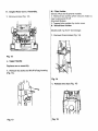
A. Bottom Plate - Agitator - Belt
1. Remove 4 screws and lift off bottom plate
(Fig. 1).
\
Fig. 1
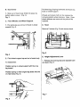
Rubber edge groomers on bottom plate are
replaceable to remove slide off of plate (Fig. 2).
Fig. 2
2. Remove agitator and belt.
To service agitator, consult the agitator section of
the service manual.

B. Duct Cover
1. Slide out of main body (Held into place by
bottom plate screws). (Fig. 3).
Fig. 3
C. Front Wheels and Wheel Support
1. Pry spring leg up and out of track in wheel
support (Fig. 4)
[]
Fig. 4
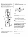
2. Pivot wheel support up and out of main body.
To reassemble:
Position spring on wheel support with the long
leg inward.
Position spring so that longest leg slides into slot
on main body (Fig. 5).
Fig. 5
Pull short leg of spring backward and hook into
track on wheel support.
Wheels and wheel shaft can be replaced by
removing plastic wheel retainers. Note: Once
wheel retainers are removed they should be
replaced.
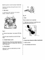
D. Hood
Remove 2 screws (Fig. 6) and remove hood.
Fig. 6
E. Height Adjustment Lever
1. Release two lockingtabs and separate cam
and lever (Fig. 7).
Fig. 7

Note the position of cam for proper reassembly
Improper assembly will cause the lever to lock
into position.
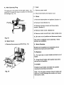
F. Main Body
1. Remove two R.H. and two L.H. trunnion
screws - marked "A" (Fig. 9)
, j'.
A A
A
Fig. 9
2. Remove hose clamp - two screws ("B") (Fig.
9)
Lift entire upper assembly up and off of main
body.
G. Handle Release Lever
Snap fit into base. Pivot lever inward and work a
screwdriver in behind to release tabs. Slide lever
out of main body.
H. Rear Wheels
Remove "E" clips and slide shaft out of main
body (Fig. 10).
Fig. 10
I. Hose
Hose is replaced as an assembly.
1. Twist hose connector to unlock from duct
assembly and remove (Fig. 11).
\
Fig. 11
J. Nozzle Hose Extension (Where Applicable)
1. Remove screw.
2. Pivot clockwise and remove.

K. Angled Hose Conn. Assembly.
1. Remove screw (Fig. 12).
'1 I
i
Fig. 12
L. Upper Handle
Replaces as an assembly.
1. Remove two bolts and lift off of bag housing.
(Fig. 13).
M. Filter Holder
Deluxe, Plus and Supreme models:
1. Remove two screws which secures holder to
bag housing and lift off.
Standard Models:
1. Trapped into position by motor cover.
N. Wand/Hose Holder
Models with "up front" tool storage.
1. Remove three screws (Fig. 14).
Fig. 14
1. Release two clips (Fig. 15)
Fig. 13 Fig. 15

2. Lift wand / hose holder out of position. Dirt
Duct is trapped into position by wand / hose
holder. On EDF models it is supplied with the
microphone. Gasket is replaceable.
Note the routing of the wiring to the switch and
microphone (where applicable) (Fig. 16).
P. Headlight Lens
1. Remove two screws and lift off lens (Fig. 17).
Fig. 17
\
\
/IICROP_"3NE
Q. EDF Printed Circuit Board Assembly
(where applicable)
1. Remove headlight bracket screw.
2. Raise panel and board out of position
3. Unsnap four tabs to separate the board and
cover.
4. Disconnect leads and replace board.
Fig. 16
O. Switch
1. Switch is exposed once upper handle and
wand / hose holder are removed. Disconnect
leads and remove switch.
To ease reassembly of the board into the cover
remove the red and green lens, snap board into
position then reassemble both the lens.
Note: The discharge of static electricity to a
circuit board can damage the components.
When removing the circuit board from the
following precautions should be taken.
1. Avoid being statically charged when handling
board.
2. Circuit board should be handled by outside
edge only.
3. DON'T touch the metal traces (circuits) on
bottom of circuit board.

R, Wire Opening Plug
This plug is in the bottom of the EDF cavity. It is
important to keep this plug in position to eliminate
air leakage (Fig. 18)
Fig. 18
S. Motor Cover
1. Remove five screws and lift off (Fig. 19)
Fig. 19
T. Cord
1. Remove strain relief.
2. Disconnect leads and replace cord.
U. Motor
1. Remove bottomplate and agitator (Section A)
2. Remove hood (Section C)
3. Remove trunnion covers and hose clamp
screws. (Section F)
4. Remove motor cover. (Section S)
5. Remove motor sound foam. (late models only)
6. Lift motor out of position and disconnect leads.
The motor is replaced as an assembly. Motor
brushes are available.
V. Motor Brushes
Brushes are supplied as an assembly which
include the brush and brush holder.
To Replace:
1, Pry open tab on brush holder and work out of
holder.
2. Grasp brush holder with needle nose pliers
and pull out of position.
To install:
Position brush holder and slide into position
insuring the terminal connection.
Note: Do not grasp outside of brush holder with
pliers as it could damage the holder and cause
the brush to stick.

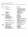
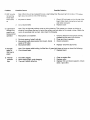
III. Troubleshooting check list - WindTunnel
The following is a guide to aid in determining the origin of a problem for which this model could conceivably be brought in
for service
Problem Possible Cause
A. Motor won't 1 Open in attachment cord.
run 2. Open in wiring.
3, Thermal protector open.
B. No pickup
at nozzle
C. No pickup
using tools
4. Switch failed.
5. Switch rod failed.
6. Motor brushes failed.
7. Motor failed.
1. Agitator belt broken.
2. Agitator brushes worn.
3. Paper bag full.
4. Secondary filter clogged.
5. Gasket on bag door damaged.
6. Gasket at base of bag door damaged,
7. Seal on dirt duct damaged.
8. Hose disconnected at rear of unit.
9. Hole in hose or hose clogged.
10. Hose from nozzle damaged or mispositioned.
11. Seals in agitator cavity or bottomplate worn or
missing,
12. Motor mount mispositioned or damaged.
1. Hose damaged or clogged.
2. Hose not locked intodirt duct.
3. Bag full.
4. Secondary filter clogged.
5. Gasket on bag door damaged,
6. Gasket at base of bag door damaged.
7. Seal on dirt duct damaged.
8. Motor mount mispositioned or damaged.
Possible Solution
1. Replace cord.
2. Check connections at motor and insulated
terminals. Check wiring to switch.
3. Replace TOC (eady models). Unplug unit
and plug it back in and check operation
(late models). Continual tripping of TOC
requires further attention.
4. Replace switch.
5. Replace upper handle assembly.
6. Replace motor brushes.
7. Replace motor assembly.
1. Replace belt.
2. Replace agitator.
3. Replace bag.
4. Clean or replace filter.
5. Replace gasket.
6. Replace gasket,
7. Replace seal.
8. Check to insure hose is locked into dirt duct
and nozzle hose extension or angled hose
connection.
9. Replace hose or clear obstruction,
10. Replace if damaged. Check to insure hose
is properly held in position by hose clamp at
main body,
11. Replace. This condition will not result in
significantsuction loss.
12. Replace or reposition. Positioniscritical.
1. Clear obstructionor replace hose.
2. Check connection.
3. Replace bag,
4, Clean or replace filter.
5. Replace gasket.
6. Replace gasket.
7. Replace seal.
8. Replace or reposition. Positioniscritical.

Problem
D EDF circuitry
not working
Green light
won't come
on
Possible Cause
Possible Solution
Note: When the unit is energized there is a slight delay then the green light illuminates If the green
light does not come on check the following:
1. No power to board
2 Circuit board failed.
E. Light doesn't
change from
green to red
during normal
operation 1.
1. Check 120 volt leads on the LH side of the
board. Also check connection at wire nut
and motor connector.
2. Replace board
Note: The red light may seldom come on during cleaning. This means your cleaner is picking up
primarily fine surface dust and lint which the system may not detect or the carpet is clean. Switch the
unit to Hi sensitivity and re-check. Also check the following:
Microphone out of position.
2. Dirt duct opening "caked" with dirt.
3. Microphone leads disconnected from board. (Small
leads on RH side)
4. Microphone failed.
F. Red light
stays on. 1.
Won't go to
green
G. Thermal 1.
protector 2.
trips 3.
1. Check to insure the microphone is firmly
pressed into the seat in the dirt duct.
2. Clean and check operation.
3. Check connection.
4. Replace- check the above first.
Note: Run cleaner while holding it off the floor. If green light does not come on check the following:
Circuit board failed. 1. Replace board.
Final filter clogged.
Motor bearing tight- motor dragging.
Thermal Protector defective.
1. Clean or replace filter.
2. Replace motor.
3. Replace TOC and check operation. Check
items 1 and 2 first.
WIRING DIAGRAM
MODELS WITH EDF
"=\
WIRING DIAGRAM
" -"1
f_rE
ATTACHMENT
V_ItE CO_IE_r _

Troubleshooting Guide
WindTunnel Cleaners

The following is a guide to aid in determining the origin of a problem for which this model could conceivably be brought in
for service.
Problem Possible Cause
A. Motor won't 1. Open in attachment cord.
run 2. Open in wiring.
3. Thermal protector open.
B No pickup
at nozzle
C. No pickup
using tools
4. Switch failed.
5. Switch rod failed.
6. Motor brushes failed.
7. Motor failed.
t. Agitator belt broken.
2. Agitator brushes worn.
3. Paper bag full.
4. Secondary filter clogged.
5. Gasket on bag door damaged.
6. Gasket at base of bag door damaged.
7. Seal on dirt duct damaged.
8. Hose disconnected at rear of unit.
9. Hole in hose or hose clogged.
10. Hose from nozzle damaged or mispositioned.
11. Seals in agitator cavity or bottomplate wom or
missing.
12. Motor mount mispositioned or damaged.
1. Hose damaged or clogged.
2. Hose not locked into dirt duct,
3. Bag full.
4. Secondary filter clogged.
5. Gasket on bag door damaged.
6. Gasket at base of bag door damaged.
7. Seal on dirt duct damaged.
8. Motor mount mispositioned or damaged,
Possible Solution
1 Replece cord.
2. Check connections at motor and insulated
terminals. Check wiring to switch
3. Replace TOC (early models). Unplug unit
and plug it back in and check operation
(late models). Continual tripping of TOC
requires further attention.
4. Replace switch.
5. Replace upper handle assembly.
6. Replace motor brushes,
7, Replace motor assembly,
1. Replace belt.
2. Replace agitator.
3. Replace bag.
4. Clean or replace filter.
5. Replace gasket,
6. Replace gasket.
7. Replace seal.
8. Check to insure hose is locked into dirt duct
and nozzle hose extension or angled hose
connection.
9. Replace hose or clear obstruction.
10. Replace if damaged. Check to insure hose
is properly held in position by hose clamp at
main body.
11. Replace. ]'his condition will not result in
significant suction loss.
12. Replace or reposition. Position is critical.
1. Clear obstruction or replace hose.
2. Check connection,
3. Replace bag.
4. Clean or replace filter.
5. Replace gasket.
6. Replace gasket.
7. Replace seal.
8. Replace or reposition. Position is critical.

Problem Possible Cause
Possible Solution
D EDF circuitry
not working
Green light
won't come
on
Note When the unit is energized there is a slight delay then the green light illuminates If the green
light does not come on check the following:
1 No power to board
2 Circuit board failed•
1 Check 120 volt leads on the LH side of the
board Also check connection at wire nut
and motor connector.
2. Replace board
E Light doesn't
change from
green to red
during normal
operation 1.
Note: The red light may seldom come on during cleaning• This means your cleaner is picking up
primarily fine surface dust and lint which the system may not detect or the carpet is clean• Switch the
unit to Hi sensitivity and re-check. Also check the following:
Microphone out of position.
2. Dirt duct opening "caked" with dirt.
3. Microphone leads disconnected from board. (Small
leads on RH side)
4. Microphone failed.
1. Check to insure the microphone is firmly
pressed into the seat in the dirt duct.
2. Clean and check operation.
3. Check connection.
4. Replace- check the above first.
F. Red light
stays on.
Won't go to
green
G. Thermal
protector
trips
Note: Run cleaner while holding it off the floor. If green light does not come on check the following:
1. Circuit board failed. 1. Replace board.
1. Final filter clogged.
2. Motor bearing tight- motor dragging.
3. Thermal Protector defective.
1. Clean or replace filter.
2. Replace motor.
3. Replace TOC and check operation. Check
items 1and 2 first.
-
 1
1
-
 2
2
-
 3
3
-
 4
4
-
 5
5
-
 6
6
-
 7
7
-
 8
8
-
 9
9
-
 10
10
-
 11
11
-
 12
12
-
 13
13
-
 14
14
-
 15
15
-
 16
16
-
 17
17
-
 18
18
-
 19
19
-
 20
20


Hoover U5445-900 Owner's manual
- Type
- Owner's manual
Ask a question and I''ll find the answer in the document
Finding information in a document is now easier with AI
Related papers
-
Hoover U5248-930 User manual
-
-
-
-
-
Hoover U8134-900 Owner's manual
-
-
-
-


