Page is loading ...
28
INSTRUCTIONS FOR USE
SPLIT CEILING-MOUNTED AIR
CONDITIONER WITH GREEN GAS
PREPARATION BEFORE USE
SAFETY PRECAUTIONS
IDENTIFICATION OF PARTS
REMOTE CONTROL
OPERATION INSTRUCTIONS
MAINTENANCE
PROTECTION
TROUBLESHOOTING
INSTALLATION INSTRUCTIONS
ELECTRICAL CONNECTION
This appliance is marked according to the European directive 2002/96/EC on Waste Electrical and
Electronic Equipment (WEEE).
This guideline is the frame of a European-wide validity of return and recycling on Waste Electrical
and Electronic Equipment.
33933047GB.fm Page 28 Monday, January 10, 2005 1:03 PM
29
PREPARATION BEFORE USE
SAFETY PRECAUTIONS
Before using the air conditioner, be sure to check and preset the following.
• Remote Control presetting
The remote control is NOT preset as Cooling Only Air Conditioner or Heat Pump by manufacturer.
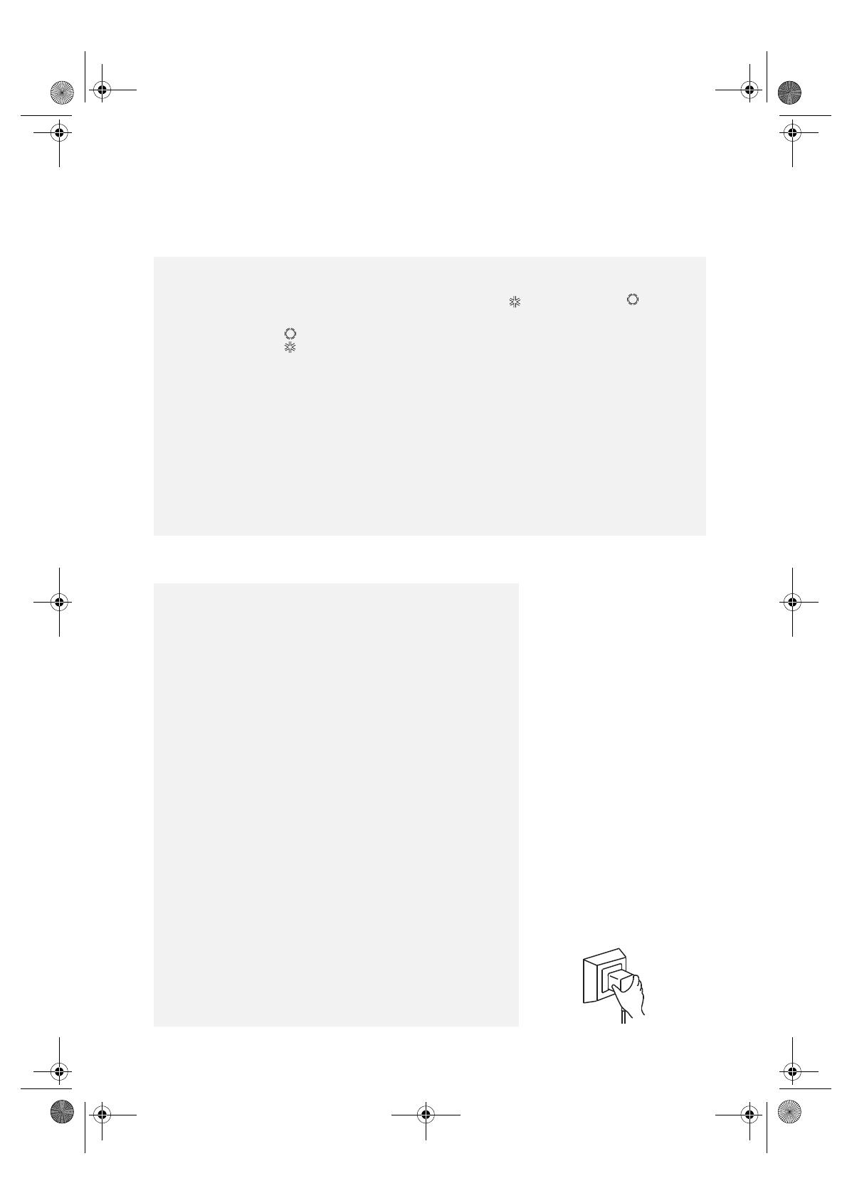
Each time the remote control batteries are replaced, the Cooling indicator and Heating indicator will flash
alternately on the remote control LCD.
The user can preset the remote control depending on the air conditioner type purchased as follows:
Pressing any button when flashes, Heat Pump is set.
Pressing any button when flashes, Cooling Only is set.
If you don’t press any button within 12 seconds, the remote control is preset as Heat Pump automatically.
Note:
If the air conditioner you purchased is a Cooling Only one, but you preset the remote control as Heat Pump,
it doesn’t matter. But if the air conditioner you purchased is a Heat Pump one, and you preset the remote
control as Cooling Only, then you CANNOT preset the Heating operation with the remote control.
• Back-light function (optional)
Pressing any button of the remote control for about 2 seconds, the back-light turns on. Once the button is released,
it automatically turns off after 10 seconds.
Note: Back-light is an optional function.
• Auto Restart Presetting
The Auto restart function is not preset by the manufacturer. To set the auto restart function, press the Emergency
button (ON/OFF) on the indoor unit for at least 5 seconds. A buzz sound will signal that the auto restart function is
set and the air conditioner is in standby.
To cancel the auto restart function, press the Emergency button (ON/OFF) on the indoor unit for at least 5 seconds.
A buzz sound will signal that the auto restart function is cancelled and the air conditioner is in standby.
Be sure not to do the following:
How to prevent faults and accidents (fires, electric shocks and other
damage).
•
Do not use the power supply circuit breaker or pull off the plug to turn it
off during operation. This may cause a fire due to spark, etc.
•
Do not twist, pull or crush the power supply cord. Doing so may damage
the cord and cause an electric shock or fire.
•
Do not insert any object in the air delivery vents. This is dangerous
because the fan rotates at high speed.
•
It is harmful to your health if the cool air reaches you for a long time. It is
advisable to let the airflow be deflected to all the room.
•
Prevent the airflow from reaching the gas burners and stove.
•
Do not operate with wet hands.
Pay attention to such a situation.
•
Do not repair the appliance by yourself. If this is done incorrectly, it may
cause an electric shock, etc.
Be sure to follow this instruction.
•
Keep the power supply circuit breaker or plug from dirt. Connect the
power supply cord to it firmly and correctly - risk of an electric shock or
a fire break out due to insufficient contact.
•
Use correct power supply
Single phase model
Use 220V~/50Hz power supply only
3-phase model
Use 380V~/50Hz power supply only
Otherwise, serious faults may occur or a fire may break out.
•
Turn off the appliance first before unplugging it from the power supply if
a malfunction occurs.
•
Do not put any objects on the outdoor unit.
Earthing is essential.
•
It is the user's responsibility to have the appliance earthed according to
local regulations by a qualified technician.
Warning:
Incorrect handling could cause a serious hazard, such as death,
serious injury.
33933047GB.fm Page 29 Monday, January 10, 2005 1:03 PM

30
IDENTIFICATION OF PARTS
Indoor unit
A
- Front panel
B
- Air louvers
C
- Corner panel
D
- Air filter
E
- Air intake
F
- Display
G
- Air outlet
H
- Remote Control
Outdoor unit
I
- Pipes and cables
L
- Drain hose
Note: Condensate water drains out in
COOLING or Dry mode.
M
- Terminal block
N
- Air outlet
NOTE:
The figures in this manual are based on the external view of a standard model. Consequently, the shape may
differ from that of the air conditioner you have purchased.
Indoor unit
Outdoor unit
33933047GB.fm Page 30 Monday, January 10, 2005 1:03 PM
31
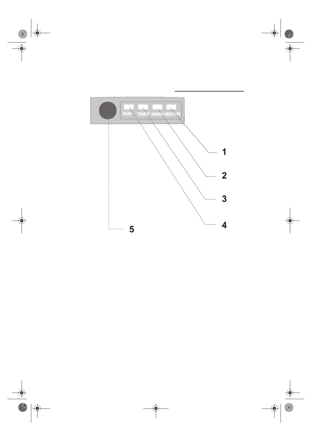
1. Heater indicator (Red)
It lights up when the electric heater (optional) is
working and goes out when the heater is off.
2. Drain indicator (Orange)
It lights up when the water pump is working. If it
blinks, a drain failure has occurred.
3. Timer indicator (Yellow)
It lights up when the timer is working.
It goes out when timer operation ends.
4. Run indicator (Green)
It lights up when the appliance is working. It blinks
for 10 seconds when the SLEEP mode is set.
5. Signal receiver
Receives signal from the remote control.
Operating and Display
33933047GB.fm Page 31 Monday, January 10, 2005 1:03 PM
32
REMOTE CONTROL
NOTE: The remote control display continues indicating even when the unit has run down.
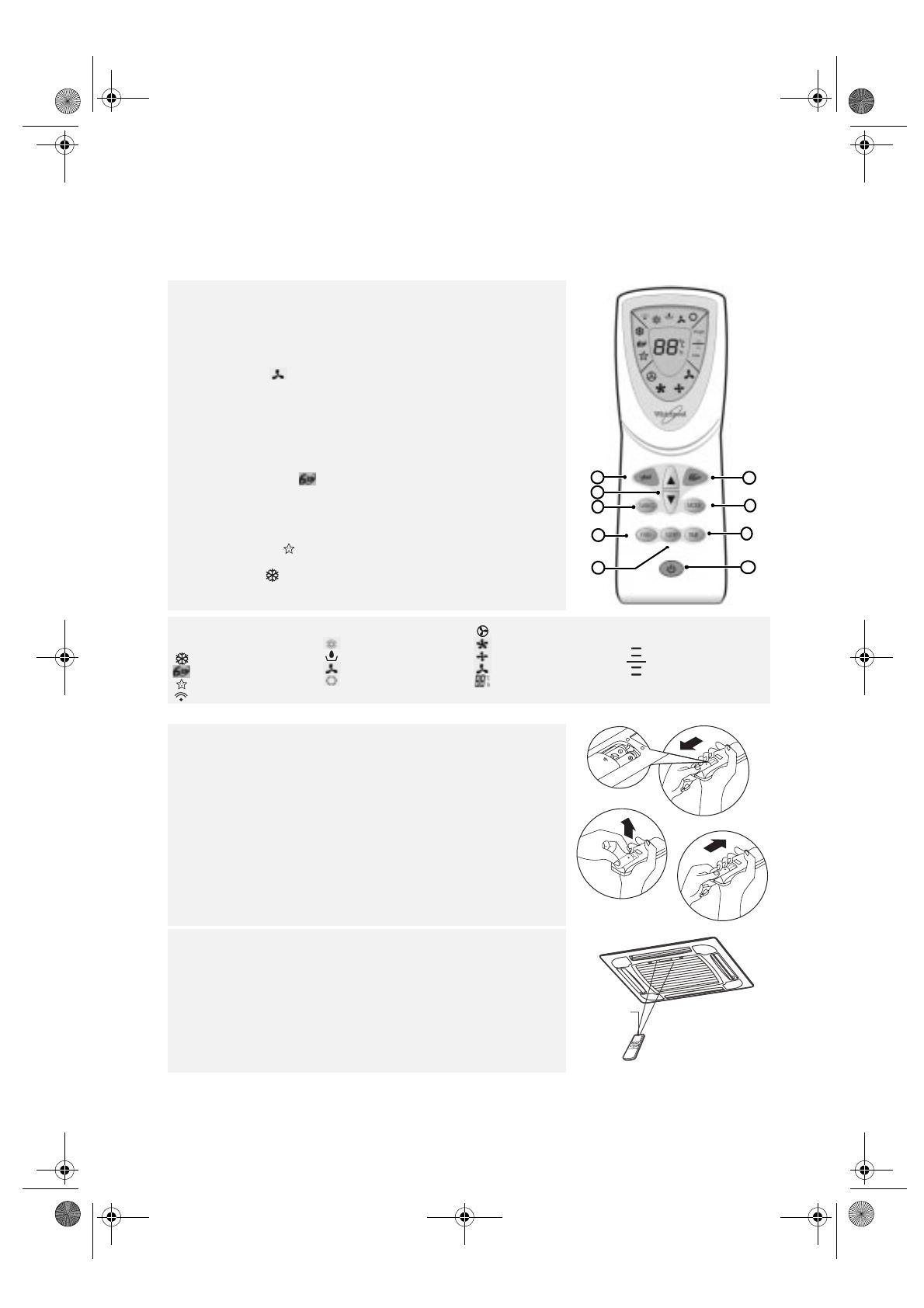
The remote control transmits signals to the system.
A. ON/OFF button
The appliance will be started when it is energized or will be stopped
when it is in operation, if you press this button.
B. MODE button
Used to select the operation mode.
C. FAN button
Used to select fan speed in sequence auto, high, medium or low.
D. ROOM TEMPERATURE SETTING buttons
Used to select the room temperature.
Used to set time in TIMER mode.
E. SWING button
Used to stop or start vertical adjustment louver swinging and set the
desired up/down airflow direction.
F. 6th Sense button
Used to enter fuzzy logic operation directly, regardless of the unit is on
or off.
G. TIMER SET/CANCEL button
Used to set or cancel the timer operation.
H. SLEEP button
Used to set or cancel Sleep Mode operation.
I. JET button
Used to start or stop the fast cooling.
(Fast cooling operates at high fan speed with 18°C set temp automatically).
H
A
F
B
E
C
D
I
G
Indication symbols on
LCD:
Jet indicator
6th Sense indicator
Sleep indicator
Signal transmit
Cooling indicator
Dry indicator
Fan only indicator
*Heating indicator
Auto fan speed
High fan speed
Medium fan speed
Low fan speed
Display set temperature
Display set timer
Used to regulate
temperature in 6th
Sense mode or Dry
mode (See page 35
“6th Sense mode” for
details)
How to insert the batteries
•
Remove the battery cover in the direction of the arrow.
•
Insert new batteries making sure that the (+) and (-) of battery are
matched correctly.
•
Refit the cover by sliding it back into position.
NOTE:
•
Use 2 LR03 AAA (1.5 V) batteries. Do not use rechargeable batteries.
Replace batteries with new ones of the same type when the display
becomes dim.
•
If the replacement is done within 1 minute, the remote control will keep
original presetting. However, if you want to change the presetting from
Heat Pump to Cool Only or Cool Only to Heat Pump, you should reload
batteries 3 minutes after removing the old ones.
(Please refer to page 29 for details.)
How to use the remote control
•
The max. distance that the signal can reach is about 7 m when pointing at
the front of indoor unit.
The appliance may not work in the following cases.
•
No signal is received.
•
The remote control is exposed to direct sunlight or strong spotlight.
Low
High
Signal
“Beep” means
receiving signal
transmitter
33933047GB.fm Page 32 Monday, January 10, 2005 1:03 PM
33
OPERATION INSTRUCTIONS
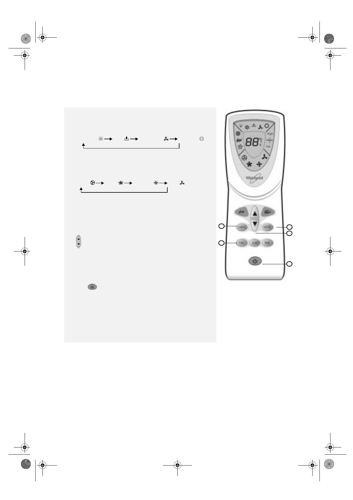
Operating modes
1. Selecting mode
Each time
MODE
button is pressed, the operation mode is changed in
sequence:
COOLING DRY FAN ONLY HEATING
IMPORTANT:
Heating mode is NOT available for cooling only air conditioner.
2. “FAN” mode
Each time the “FAN” button is pressed, the fan speed is changed in
sequence:
AUTO HIGH MEDIUM LOW
IMPORTANT:
•
In “FAN ONLY” mode, only “High”, ”Medium” and “Low” are
available.
•
In “DRY” mode, airflow is set at “Low” automatically, “FAN” button
is ineffective in this case.
3. Setting temperature
Press once to raise temperature setting by 1°C
Press once to lower temperature setting by 1°C
Range of available set temperature:
*HEATING, COOLING 18°C ~ 32°C
DRY room temperature ± 2°C
FAN ONLY unable to set
*NOTE: Heating mode is NOT available for cooling only models.
4. Turning on
Press button, when the appliance receives the signal, the RUN
indicator of the indoor unit lights up.
SWING, 6th Sense, TIMER, SLEEP and JET operation modes will be
specified in the following pages.
IMPORTANT:
• Changing modes during operation, sometimes the unit does not
response at once. Wait 3 minutes.
• During heating operation, air flow is not discharged at the
beginning. After 2-5 minutes, the air flow will be discharged until
temperature of indoor heat exchanger rises.
• Wait 3 minutes before restarting the appliance.
1
3
4
5
2
33933047GB.fm Page 33 Monday, January 10, 2005 1:03 PM
34
5. Airflow direction control
Vertical airflow control
Press the SWING button to set the airflow angles.
The airflow direction can be adjusted to your own requirement by pressing
the “SWING” button (
5
).
Swinging airflow:
Press the SWING button once, the fan motor will start operating and the air
louvers will swing vertically.
Desired airflow direction:
Press the SWING button again when the flaps swing to the desired angle, the
fan motor will stop operating and the air louvers will stop swinging.
•
Do not turn the air louvers manually, otherwise a malfunction may occur.
If that happens, first turn off the unit and disconnect it from the power
supply, then restore the power supply again.
•
It is advisable not to allow the air louvers tilt downward for a long time in
COOLING or DRY mode to prevent dew from forming and dripping
down.
•
Condensate may form and drip from the indoor unit during COOLING or
DRY operation in high humidity conditions (above 85%).
After the unit has been used for a long time, the air intake may be
covered with dust. Wipe it off with a soft cloth.
Timer mode
Use the “TIMER” button to set a switch-on time when you go out so that
you find a comfortable room temperature when you come back. You can
also set a switch-off time.
Timer setting
•
Set switch-on time when the appliance is off.
•
Setting a switch-off timer during operation.
•
As time goes by, LCD displays the remained time.
•
The previous set time is stored and the next set time begins with the
previous set one.
•
On-timer and off-timer can not be set at the same time.
•
The room may not reach your desired temperature within the preset
time because of different size of room.
•
The TIMER indicator on the front panel lights up when timer is in use,
and lights off when it is finished or cancelled.
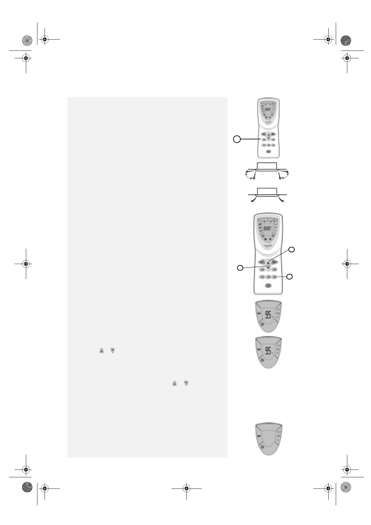
1. E.g. setting the next operation after 9.5 hours
Set the desired operating mode, temperature and indoor fan speed,
then press the TIMER button (1); “h” will flash on the LCD.
2. E.g. setting the next operation after 9.5 hours
Point the remote control at the signal receiver of the indoor unit, and
press the or button (2) when “h” flashes. Choose the time you
desire, then press the TIMER button.
A “beep” can be heard:
•
Timer indicator on the indoor unit lights up.
•
“h” stops flashing.
Important: Press the TIMER button, “h” flashes on the LCD,
then you can set the time. Each time the or button is
pressed:
If the desired time is within 10 hours, the set time increases or
decreases by 0.5 hour.
If the desired time is beyond 10 hours, the set time increases or
decreases by 1 hour.
The time that can be set ranges between 0.5 and 24 hours
3. E.g. cancelling the switch-on time after 9.5 hours
To cancel the set time: press the TIMER button again, a “beep” can be
heard and the timer indicator on the indoor unit lights off.
5
(desired direction)
(desired direction)
1
2
2
33933047GB.fm Page 34 Monday, January 10, 2005 1:03 PM

35
6th Sense mode
Electric heating mode (optional)
When you feel the temperature is not warm enough or need heat faster in heating mode, use the electric heater for
extra fast heat.
How to use the electric heater in heating mode
•
Use the remote control to set the electric heating mode.
•
Press the “HEATER” BUTTON in heating mode. The HEATER indicator on the indoor unit lights up and the
electric heater starts to function. (When the temperature is sufficiently warm, the electric heater stops
automatically. It will restart when the temperature decreases again).
•
Press the “HEATER” button again in electric heating mode to stop the function. The HEATER indicator turns off,
the unit returns to heating mode without the aid of the electric heater.
•
When you do not want to use the electric heater, it is recommended to switch off the power supply of the electric
heater for safety.
Pressing the 6th Sense button, the unit enters fuzzy logic operation directly regardless whether the unit is on or off. In
this mode, temperature and fan speed are automatically set according to the actual room temperature.
Operation mode and temperature are determined by indoor temperature
Heat pump models
Indoor temperature
Operation
mode
Target temperature
21°C or below HEATING 22°C
21°C - 26°C DRY
Room temperature decreases 1.5°C after
operating for 3 minutes
Over 26 COOLING 26°C
Cooling only models
Indoor temperature
Operation
mode
Target temperature
26°C or below DRY
Room temperature decreases 1.5°C after
operating for 3 minutes
Over 26 COOLING 26°C
Important: 6th Sense button is ineffective in JET mode.
Note: Temperature, airflow and direction are controlled automatically in 6th Sense mode. However, a
decrease or rise of up to 2°C can be set with the remote control if you still feel uncomfortable.
A decrease or increase up to 2°C can be set in 6th Sense mode
Your feeling Button Adjustment procedure
Slightly warmer
A decrease up to 2°C can be set
Press once to lower the set temp by 1°C
Press twice to lower the set temp by 2°C
Slightly cooler
A rise up to 2°C can be set
Press once to raise the set temp by 1°C
Press twice to raise the set temp by 2°C
Uncomfortable because of unsuitable air flow
volume.
Indoor fan speed alternates among High,
Medium and Low each time this button is
pressed.
Uncomfortable because of unsuitable flow
direction.
Press it once, the vertical adjustment louver
swings to change vertical airflow direction. Press
it again, swings stops. For horizontal airflow
direction, please refer to the previous page for
details.
33933047GB.fm Page 35 Monday, January 10, 2005 1:03 PM
36
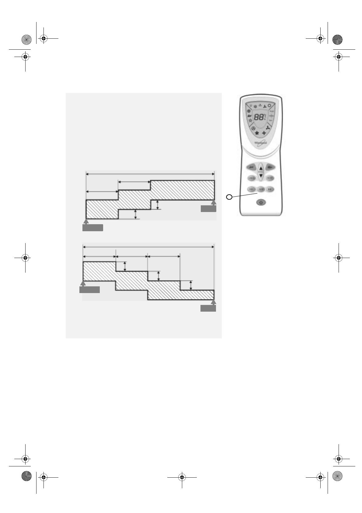
Sleep mode
SLEEP mode can be set in COOLING or HEATING operation mode.
This function gives you a more comfortable environment for sleep.
In SLEEP mode,
•
The appliance will stop operation automatically after operating for
8hours.
•
Fan speed is automatically set at low speed.
•
*The set temperature will rise by max. 1°C if the appliance operates in
cooling mode for two hours, then it will remain constant.
•
The set temperature will decrease by max 3°C is the appliance operates
in heating mode for 3 hours, then it will remain constant.
COOLING
**HEATING
*: In cooling mode, if room temperature is 26°C or above, set
temperature will not change.
**: Heating is NOT available for cooling only air conditioner.
1 hour
8 hours timer
1 hour
Rise by 0.5°C
SET
TEMP.
START
Rise by 0.5°C
STOP
Decrease by
1°C
STOP
START
SET
TEMP
.
8 hours timer
Decrease
by 1°C
Decrease
by 1°C
1 hour
1 hour
1 hour
1
33933047GB.fm Page 36 Monday, January 10, 2005 1:03 PM
37
MAINTENANCE
Before using a ladder or other means, inspect it to make sure it is safely placed.
Indoor unit maintenance
Unplug from the power supply
Turn off the appliance before unplugging.
Wipe with a soft and dry cloth.
•
Use lukewarm water (below 40°C) to clean the appliance if it is very dirty.
•
Use a dry and soft cloth to clean it.
Never use volatile substances such as gasoline or polishing powder to
clean the unit.
Never sprinkle water on the indoor unit
•
Dangerous! Electric shock!
Dry the inside of the unit
Operate the appliance in FAN ONLY mode for half a day to dry the inside of
the unit on a sunny day.
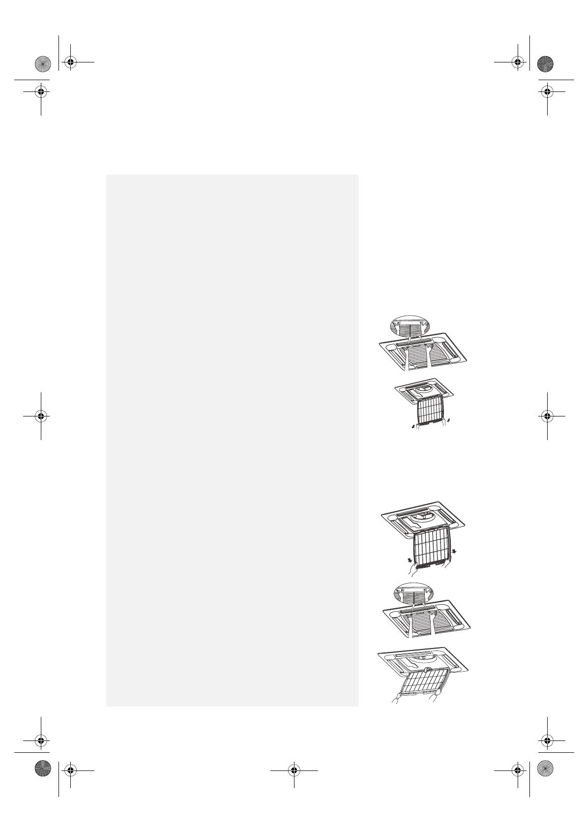
Air filter maintenance
•
Unplug from the power supply, then use a ladder or other safe means to
gain access the indoor unit.
•
Press the buttons on the air intake grill with both hands.
•
Remove the air intake grill.
•
Open the air intake grill.
•
Grasp the bottom corners of the air filter and pull downward.
•
Remove the air filter.
Air filter cleaning
Cleaning
•
Remove the dust from the air filter with a vacuum cleaner.
•
Clean it with water and neutral detergent.
•
Dry it thoroughly in a cool and shaded place.
Note:
Do not place the filter next to high heat or fire, it may cause
ageing, deformation or even burning of the plastic parts.
•
Replace the filter in its original position after cleaning.
•
Lock the four corners of the air filter.
•
Refit the air intake grill.
Air intake grill cleaning
•
Unplug from the power supply, then use a ladder or other safe means to
gain access the indoor unit.
•
Press the buttons on the air intake grill with both hands.
•
Remove the air intake grill.
•
Open the air intake grill.
•
Grasp both sides and remove it as shown below.
•
Clean it with water and neutral detergent.
•
Dry it thoroughly in a cool and shaded place.
•
Grasp both sides of the air intake grill and replace it in reverse order to
refit the air intake grill.
33933047GB.fm Page 37 Monday, January 10, 2005 1:03 PM
38
PROTECTION
Operating condition
Protection device features
Noise pollution
Inspection
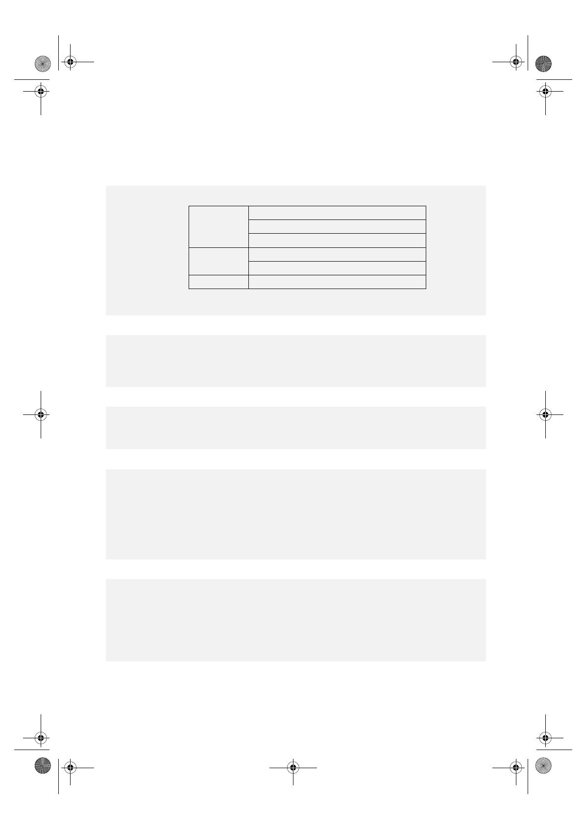
HEATING mode features
The protective device may trip and stop the appliance in the cases listed below.
If the air conditioner runs in “COOLING” or “DRY” mode with door and/or window open when relative humidity is
higher than 85%, dew will drip down from the outlet.
HEATING
Outdoor air temperature is over 24°C
Outdoor air temperature is below -5°C
Room temperature is over 27°C
COOLING
Outdoor air temperature is over 43°C
Room temperature is below 21°C
DRY
Room temperature is below 18°C
The protection device will trip in the following cases:
•
After stopping the appliance and restarting it immediately or after changing mode during operation, there is a delay
of 3 minutes before it starts operation.
•
Switching on power supply and turning on the appliance at once, you need to wait about 20 seconds.
•
If all operation has stopped, press the “ON/OFF” button again to restart. Set the timer again if it has been cancelled.
•
Install the air conditioner in a place that can bear its weight in order to operate more quietly.
•
Install the outdoor unit in a place where the air discharged and the operating noise do not annoy your neighbours.
•
Do not place an obstacle in front of the outlet of the outdoor unit as it may affect the air conditioner operation and
increase the noise level.
After using the appliance for a long time, the following items should be inspected:
•
Power supply cord and plug overheating or even a burned smell.
•
Abnormal operating sound or vibration.
•
Water leakage from indoor unit.
•
Metal cabinet electrified.
IMPORTANT:
Stop the air conditioner if any fault occurs.
It is advisable to check the air conditioner carefully every five years even if none of the above faults occur
the air conditioner.
Preheating
At the beginning of HEATING operation, the airflow from the indoor unit is discharged 2-5 minutes later.
Defrosting
In HEATING mode the appliance will defrost (de-ice) automatically to raise efficiency. This procedure usually takes 2-
10 minutes. During defrosting, fans stop operation.
When the defrosting function ends, it returns to HEATING mode automatically.
It is hard to raise the room temperature when the outdoor temperature is very low. Use the air conditioner together
with other heating appliance in this case.
33933047GB.fm Page 38 Monday, January 10, 2005 1:03 PM
39
TROUBLESHOOTING
Trouble Analysis
Does not run
• Is the protection device or fuse blown?
• Sometimes it stops working to protect the appliance.
• Are the remote control batteries low?
• Is the plug unplugged?
No cool or warm air
• Is the air filter dirty?
• Are the intakes and outlets of the air conditioner obstructed.
• Is the temperature set properly.
Ineffective control
• If there is a strong interference (from excessive static electricity
discharge, power supply voltage abnormality) presents, operation will
be abnormal. In this case, unplug from the power supply and plug in
after 2-3 seconds.
Does not operate
immediately
• Changing mode in operation, there may be a delay of 3 minutes.
Peculiar smell
• This odor may come from another source such as furniture or others.
A sound of running-water
• Defrosting sound in heating mode.
• Caused by the flow of refrigerant in the air conditioner, not a fault.
A “craking” sound is be
heard
• Caused by the expansion or contraction of the front panel because of
temperature changing, not a fault.
Spray mist from the outlet
• Mist appears when the room air becomes very cold as during
operation in “COOLING” or “DRY” mode.
33933047GB.fm Page 39 Monday, January 10, 2005 1:03 PM
40
INSTALLATION INSTRUCTIONS
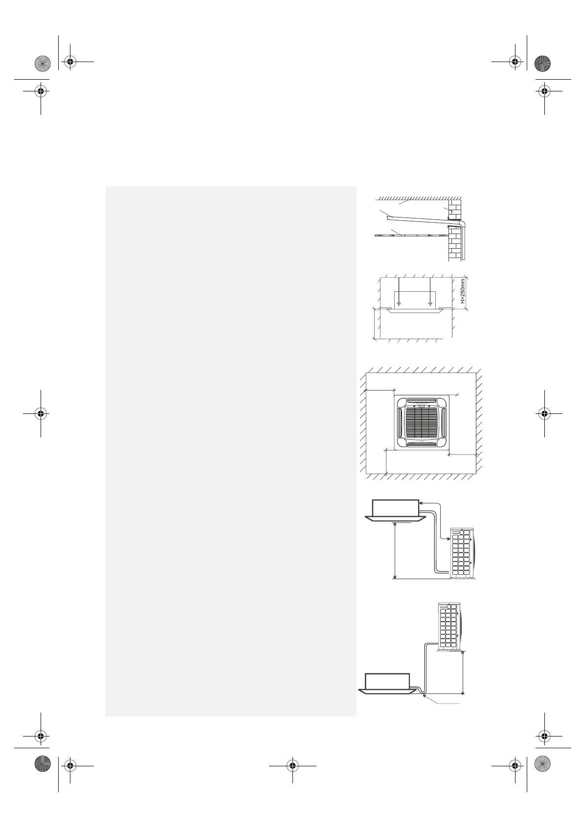
Select the best location
Location for Installing the Indoor Unit
•
Where there is no obstacle near the air outlet and air can be easily blown
to every corner.
•
Where the piping can be easily arranged. It is preferable to have a special
draining facility.
•
Where the ceiling is strong enough to bear the weight of the indoor unit
and will not increase operating noise and vibrations.
•
Leave the required clearance between the unit and roof, and between the
floor and wall as shown in the figure to the right.
•
Do no put anything near the air intake that could obstruct it.
•
Keep the unit and remote control 1 m or more from the television, radio,
etc.
•
Keep the main unit at least 5 m from fluorescent lamps.
•
The maximum piping length between indoor and outdoor units is 20 m,
and the maximum elevation between the units is 10 m.
•
Avoid installing the appliance in a dirty or greasy place.
Height of ceiling board
•
Normally, keep the ceiling board 2 m - 3.5 m from the floor.
Location for Installing the Outdoor Unit
•
Install in a convenient and well-ventilated place; avoid installing it where
flammable gas could leak.
•
Keep the outdoor unit at least 100 mm from the wall (over 500 mm at the
side of the piping).
•
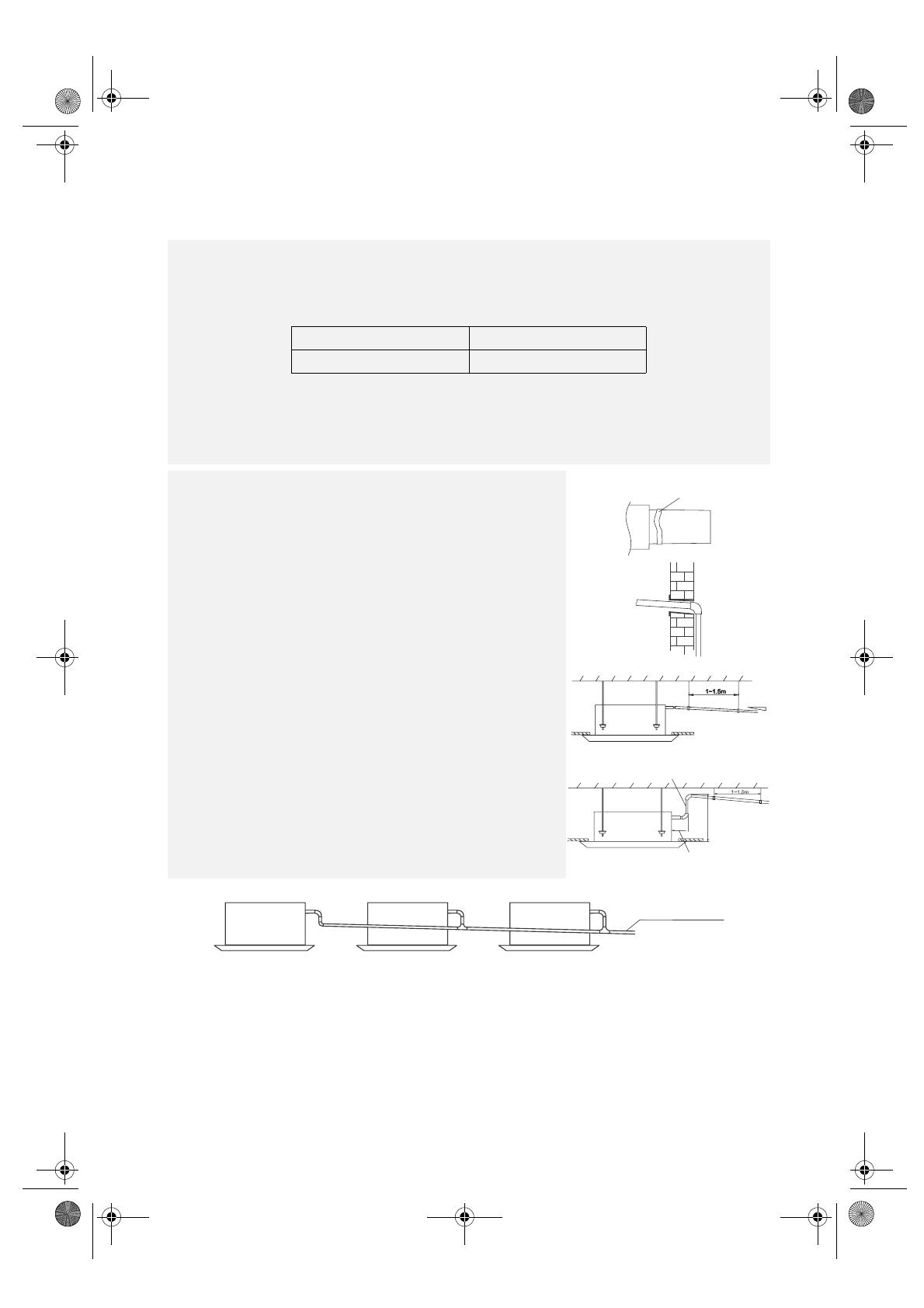
The maximum length of connecting piping is 20 m. If it exceeds 10 m,
additional refrigerant (20 grams per metre) is needed. If the outdoor unit
is higher than the indoor unit, connect an elbow to the entry pipe of the
indoor unit (see figure to the right).
•
When installed in a dirty and greasy place, near a vulcanization gas exit or
highly salty seashore, make sure to carry out insulation.
•
Avoid installing it at the roadside where it could be soiled with muddy
water.
•
Install where your neighbours will not be annoyed by operating noise and
discharged air.
•
A fixed base where operating noise will not increase.
•
Where the air outlet is not obstructed.
Drain pipe
Roof
Wall
Ceiling
Over 1000mm
Over 1500mm
Over 1500mm
Over 1500mm
Over 1500mm
Elevation
Indoor unit
Outdoor unit
Outdoor unit
Elevation
Indoor unit
Returned
oil elbow
Ground
ÅÆ
10cm.
33933047GB.fm Page 40 Monday, January 10, 2005 1:03 PM
41
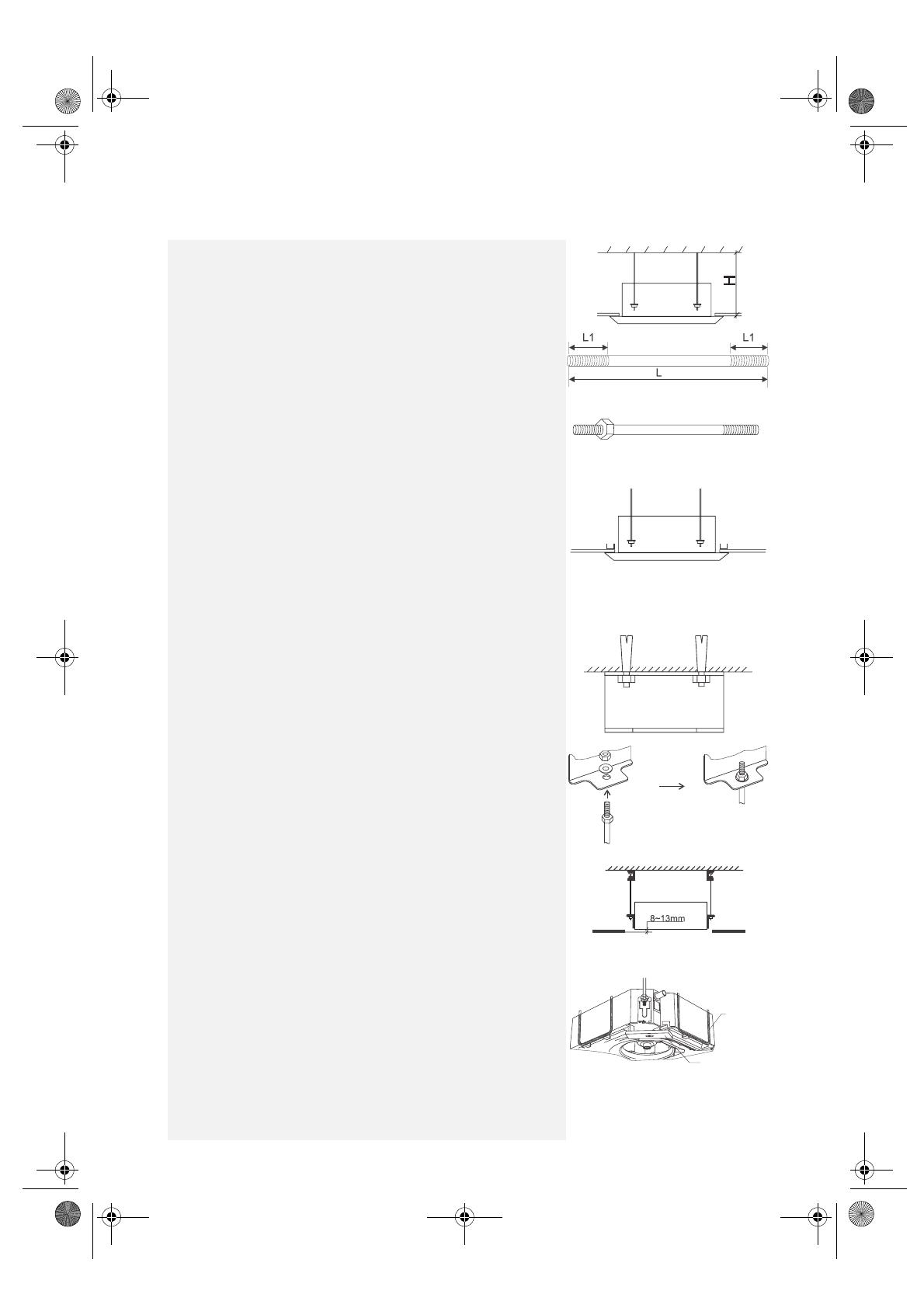
Indoor unit installation
(Note: The instructions below are only applicable to a house made of
concrete.)
•
Measure the distance H between the roof and ceiling board;
•
Make four suspending poles with M10 screw threading on both ends
(metric system) as the shown in the figure on the right. (processed with
10 pole).
L and L1 values are calculated as follows:
L1=50mm (when H<255mm, L1=40mm)
L=1.5L1+H-230 (unit: mm)
•
Screw 4 nuts onto the threaded ends of the suspending poles as shown on
the right:
•
Take the template out of the packing carton of the indoor unit. Do not fold
it, just use it to choose the installation location and direction of the unit on
the roof and ceiling. Press the template tightly onto the surface of the roof,
mark 8 holes for the expanding bolts with a pencil, then take off the
template and finally drill the holes. It is preferable if the depth of the holes
just reveal the thread of the poles.
•
Cut an opening (880x880) on the ceiling board with the help of the
template, make sure to follow the same direction of the holes for the roof
bolts. Fix the edges of the opening with the [-shaped aluminium bars.
•
Mount the attached suspending brackets with M8X50 expanding bolts on
the roof surface. Make sure to tighten the expanding bolts and nuts well.
The opening of the suspending brackets should face outward as shown:
•
Take the suspending poles with a nut on one end, mount them on the
fixed suspending brackets, then tighten the nuts and washers on the top
of the suspending brackets.
•
Fix the main unit onto the suspension poles with nuts and washers.
The nuts on the bottom should turn to about half of the thread length.
(Note: The above operation requires at least 2 people)
•
Adjust the nuts on the bottom of the suspension poles, so that the bottom
of the unit is 8-13 mm higher than the ceiling board (see figure above).
Then adjust each corner of the bottom horizontally with a levelling ruler
(Levelling inaccuracy: 1%)
Water pipe
Levelling ruler
33933047GB.fm Page 41 Monday, January 10, 2005 1:03 PM
42
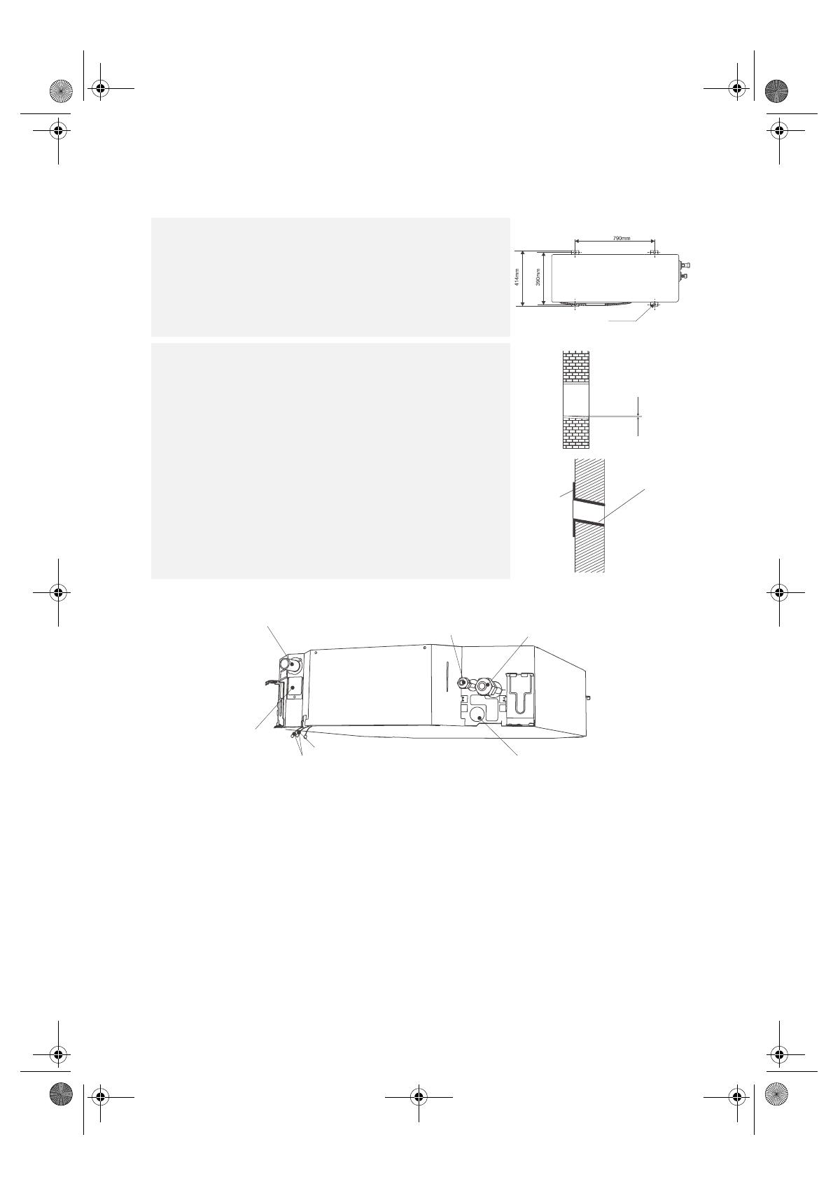
Pipe and cable connections
Outdoor unit installation
•
Install it on a strong and flat surface or bracket.
•
Keep it at least 150 mm above the ground.
•
Fix it well with 4 M8X60 bolts to avoid vibration or other accidents.
4-12 x 18 hole
Drill a hole for piping
•
Drill a hole in the wall if it is necessary to put the pipes and cables through
the wall.
•
The hole should be angled downward to the exterior to allow for easy
drainage.
•
To keep the hole tidy, install a wall hole sleeve and sleeve cap.
Indoor Outdoor
5mm (tilt
downward)
Wall
sleeve cap
Wall hole
sleeve
Indoor Outdoor
Drain pipe connector
Gas delivery pipe connector
Suction pipe connector
Check water pump here
Connect to louver motor wire
Connect to remote control indicator wire
Hole for cords and cables
33933047GB.fm Page 42 Monday, January 10, 2005 1:03 PM

43
Outdoor unit piping connection
Pipe preparation
Measure the length of pipes according to the location and direction of indoor
and outdoor units and the wall hole.
Cut the copper tube (X10 and X 16) correctly with a pipe cutter.
Make sure to completely remove the burrs from the cut cross section of
pipe/tube.
Remove the nuts from the indoor unit. When removing the nuts, some gas
may escape. It is protective gas. Then remove the plastic plug from the pipe
according to its location.
Pipe connection
•
Align the centre of the flare opening and connector.
•
First finger-tighten the flare nut clockwise, then use a wrench.
•
Use the tightening torque table on the right as a guideline. Excessive
tightening damages the flare section.
•
Bind up all the joints of both gas and liquid pipes with thermal insulation
material and fix tightly with wrapping tape (this procedure should be done
after the leak test).
•
Wrap all joints well, otherwise dew may form and drip.
•
The gas pipe and liquid pipe should be taped and wrapped separately.
•
Adjust the position of pipes, and fix them well.
Outdoor unit section
1.
Remove the high and low pressure valve caps with a wrench.
2.
Remove the plastic cover of the connecting pipes.
3.
Align the pipe and connector with one hand and screw the flare nut onto
the connector with the other. Then tighten with a wrench
(see figure to the right).
Note: If the suspended section of the connecting pipes exceeds 2 m, a fixing
bracket should be installed every 1.5 m to support the weight.
Model Outer dia A (mm)
24K
Ø 9.53 Ø 12.0 ~ 12.4
Ø 16 Ø 18.6 ~ 19.0
41K
Ø 9.53 Ø 12.0 ~ 12.4
Ø 19 Ø 23.5 ~ 24.0
Model
Pipe outer dia
(mm)
Tightening torque
(N.m)
24K
Ø 9.53 34 ~ 39
Ø 16 73 ~ 78
41K
Ø 9.53 34 ~ 39
Ø 19 98 ~ 137
Connecting pipe
Small pipe (liquid)
Flare nut
Connector
High pressure valve
Low pressure valve
Apply some
chilled machine oil
Liquid pipe
Gas pipe
Insulation
material
Wrapping
tape
Large pipe (gas)
33933047GB.fm Page 43 Monday, January 10, 2005 1:03 PM

44
Air purging
After connecting the indoor and outdoor units, evacuate air and moisture from the refrigerant system using a vacuum
pump, as shown below.
How to purge air tubes:
•
Unscrew and remove caps from 2 and 3-way valves.
•
Unscrew and remove cap from service valve.
•
Connect vacuum pump flexible hose to the service valve.
•
Start the vacuum pump for 10-15 minutes until it reaches an absolute vacuum of 10 mm Hg.
•
With the vacuum pump still running close the low pressure knob on the vacuum pump manifold. Then stop the
vacuum pump.
•
Open the 2-way valve 1/4 turn, then close it after 10 seconds. Check tightness of all joints using liquid soap or an
electronic leak detector.
•
Turn the 2 and 3-way valves stem. Disconnect the vacuum pump flexible hose.
Vacuum pump
Connect to indoor unit
Open position
Spindle
Needle
Service port capValve core
Connect
to outdoor
unit
Indoor unit
Flow direction R407c refrigerant
3-way valve
Service port
(2) Turn
(8) Tighten
(7) Turn to fully open the valve
(1) Turn
(8) Tighten
Valve cap
2-way valve
(6) Open 1/4 turn
(7) Turn to fully open the valve
Valve cap
(1) Turn
(8) Tighten
3-way valve diagram
33933047GB.fm Page 44 Monday, January 10, 2005 1:03 PM
45
After evacuating the air, check for tightness of all the joints of indoor and outdoor units with a halogen detector or liquid
soap before wrapping.
Adding refrigerant:
The refrigerant volume of the models in this manual is based on using 10m connecting pipes. If your connecting pipes
are longer than 10m, additional refrigerant should be charged according to pipe length (L).
The additional refrigerant must be charged in the condition that it is running in the system. The refrigerant should be
charged to the system from the service port of the low pressure valve. Be careful not to allow air enter the system while
adding refrigerant.
IMPORTANT FOR ANY SERVICE ACTION: When charging R407C refrigerant into the system, make sure
to charge in liquid state. Otherwise, the chemical composition of the refrigerant (R407C) inside the system
may change and affect the performance of the air conditioner.
Max pipe length (m) Additional refrigerant (Kg)
20 (L-10) x 0.02
Drain pipe connection
•
Connect the large end (inner diameter 25mm, outer diameter 32mm) of
the drain hose to the drain port of the main unit, then clamp it well.
•
Measure the distance from the drain pipe to the outside of wall, then cut
a Ø 25 PVC tube (inner diameter 22mm) according to this length.
•
Apply epoxy glue on the small end (outer diameter 21 mm) of the drain
hose, then connect it to the PVC tube.
•
Direct the other end of the PVC tube to the outside of the wall, connect
to a downward pipe with a Ø 25 elbow (make sure to attach the joints
well with epoxy glue).
•
If the suspended section of the indoor drain pipe exceeds 2 m, a
supporting bracket should be fitted every 1-1.5 m. The drain pipe must be
inclined downward with a gradient over 1/100 to ensure correct drain
flow. The drain pipe should not have too many bends as they may prevent
water from draining.
•
Make sure the indoor part of the drain pipe is thermally insulated.
Otherwise, condensate may form and drip on the ceiling board.
•
If the indoor section of the drain pipe is too long, proceed as described.
•
When several units drain together, proceed as described.
Epoxy glue
Dn15pipe
Below 300mm
Below 700mm
Over 1/100
Collective drain pipe
33933047GB.fm Page 45 Monday, January 10, 2005 1:03 PM

46
Electrical Wiring Diagram
The electrician should cut proper length cables and cords, in compliance with local electrical and fire safety codes.
Electrical work
Cable specifications
•
The cross section of the wires above is a minimum one. If the connecting cord between the indoor and outdoor units
is very long, use a cable with a larger cross section to avoid voltage drop.
•
The user should prepare a 2.5 mm earth wire for the whole unit.
Model
Power
supply
Power cord
Electric heater
cord (optional)
Control cable
Power
connecting cord
Defrost cable
Spec. Spec. Spec. Spec. Spec.
3 PHASE
MODEL
(24K)
3-phase
380V
3N~50Hz
5x2.5mm
2
2x2.5mm
2
3x0.75mm
2
3x1.5mm
2
2x0.3mm
2
3 PHASE
MODEL
(41K)
3-phase
380V
3N~50Hz
5x2.5mm
2
4x1.5mm
2
4x0.75mm
2
SINGLE
PHASE
MODEL
(24K)
Single phase
220V3-phase
380V~50Hz
3x2.5mm
2
2x2.5mm
2
3x0.75mm
2
3x1.5mm
2
2x0.3mm
2
Electrical work cautions
•
Make sure to understand the requirements on the rating label before performing electrical work. Follow the wiring
diagram while carrying out the electrical connections.
•
Use a special power supply and leakage protection device for the air conditioner.
•
The indoor and outdoor units must be earthed correctly.
•
All connections must be in accordance with the relevant wiring diagram, and should comply with local regulations.
Incorrect connection could result in damage to the unit or even a hazard.
•
Keep the cables away from the compressor or rotating fans.
•
Do not change the internal wiring.
•
Make sure to fix the wires well. Incomplete connection or fixing of wires could cause a fire.
Electrical connection:
•
Remove the terminal block covers from the indoor and outdoor units.
•
Connect the power connecting cord and control cable. Fix them with a cable clamp after connecting.
•
Earth the indoor and outdoor units. Incorrect earthing may cause an electric shock.
•
After electrical connection, replace the covers.
Power
supply
Outdoor
unit
Defrost cable
Control cable
Power cable (has polarity)
Electric heater power cord
Indoor
unit
Power
supply
Power supply cord
Main switch/fuse
(prepared by user)
Main switch/fuse
(prepared by user)
Control board
Outdoor terminal block
Terminals
Control box cover
Terminal block cover
Terminal block cover
INDOOR UNIT
OUTDOOR UNIT
33933047GB.fm Page 46 Monday, January 10, 2005 1:03 PM
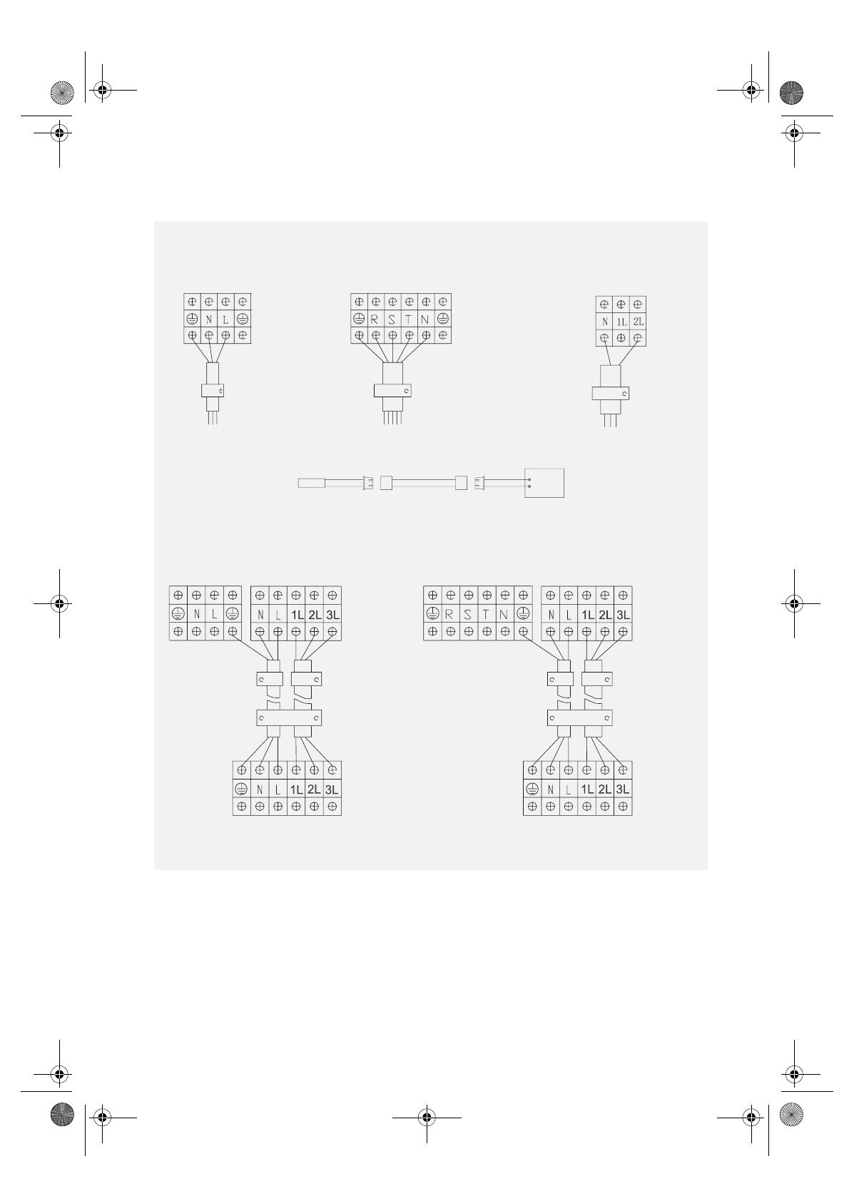
47
Match the colour when connecting the indoor and outdoor units (as shown in the figure above)
Note: Make sure to wrap the cords properly with adhesive tape after wiring.
Electrical work (For 24K)
Power supply cord Electric heater power cord (optional)
SINGLE PHASE MODEL
(220V/50HZ/single phase)
3- PHASE MODEL
(380V/50HZ/3 Phase)
Yellow/Green
Blue
Brown
Cable clamp
Power supply cord
Outdoor terminal
Yellow/Green
Re
d
White
B
lac
k
Blue
Outdoor terminal
Cable clamp
Power supply cord
Indoor
terminal
R
e
d
Red
Cable clamp
Power supply cord
Defrost cable
Thermistor Defrost cable
Indoor unit PCB
Power connecting cord and control cables
SINGLE PHASE MODEL
3- PHASE MODEL
Outdoor unit
Outdoor terminal
Outdoor terminal
Y
e
l
l
o
w
/
G
r
e
e
n
B
lu
e
Brown
Black
V
io
l
e
t
O
r
a
n
g
e
Cable clamp
Control cable
Cable clamp
Power connecting cord
Indoor unit
Indoor terminalIndoor terminal
Outdoor unit
Outdoor terminal
Outdoor terminal
Y
e
l
l
o
w
/
G
r
e
e
n
B
lu
e
Brown
V
io
l
e
t
O
r
a
n
g
e
Cable clamp
Control cable
Cable clamp
Power connecting cord
Indoor unit
Indoor terminalIndoor terminal
Y
e
ll
ow/Green
B
l
u
e
B
ro
w
n
Black
V
i
o
l
e
t
O
r
a
n
g
e
Y
e
ll
ow/Gre
e
n
B
lu
e
B
ro
w
n
Black
V
i
ol
e
t
O
r
a
n
g
e
Black
33933047GB.fm Page 47 Monday, January 10, 2005 1:03 PM
/