PITT Cooking Systems Elbrus Installation guide

Type
Installation guide
Made in Holland
Installation and handling instructions
PITT
®
cooking in kitchen worktops
These documents contain instructions to securely and successfully install PITT
®
cooking into
kitchen worktops. Furthermore, they indicate which level of craftsmanship is required. To
make a warranty claim, installation procedures should be applied as described. PITT
®
cooking
is exclusively intended for consumer use.
1. Materials suitable for PITT
®
cooking 2
2. Manufacturing recesses (cut-outs) 3
Cut-outs Solid Surface
5
3. Installation kitchen worktop 7
4. Installation PITT
®
cooking in the kitchen worktop 8
Content
1a. PITT
®
cooking can be built into:
Compact board (eg. Trespa)
Solid Surface
Quartz Composite (eg. Caesarstone, Silestone)
Concrete
Glass
Natural stone (eg. granite, marble)
Stainless steel
Ceramics
PITT
®
cooking should never be installed into solid wood and worktops with an HPL
top layer.
1b. The minimum thickness of the core material is 4 mm. For Solid Surface, Quartz
composite, compact board and natural stone applies a minimum thickness of the core
material (solid) of 10 mm. For all materials, a maximum thickness of 35 mm applies.
The bottom of the core material needs to be completely flat, in order to bring the
heat conductor in full contact with the worktop.
1. Material suitable for PITT
®
cooking
!
!
2
2.
Manufacturing recesses (cut-outs)
!
The guidelines of the kitchen manufacturer and/or the manufacturer of the kitchen
worktop should always be strictly followed.
2a. The C-size should be at least 50 mm (fig.1). With the XL models, it should be at least 75 mm
(fig.2). The distance between the cut out and the sides (left or right) of the worktop should
be at least 150 mm.
Fig. 1 Fig. 2
2b. The insides of the recess(es) should be smooth and even (fig. 3). Irregularities can
cause cracking (fig. 4).
Fig. 3 Fig. 4
2C. On the top and bottom of the recess(es) should be a facet of at least 1x1 mm be
applied (with exception for Solid Surface) (fig. 5).
Fig. 5
Facet 1x1 mm
35
35
3
2.
Manufacturing recesses (cut-outs)
2H. Adhesive connections and/or interconnections should never intersect the recess(es). These
should have a distance of at least 250 mm to the recess(es) (fig. 6 and 7).
Fig. 6 Fig. 7
4
2.
Manufacturing recesses (cut-outs) | Solid Surface
!
The guidelines of the manufacturer of the Solid Surface material should always be strictly
followed.
In case of Solid Surface the following extra instructions apply:
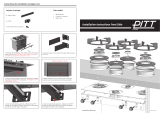
2d. Use a router or CNC machine to prevent jagged recesses.
Radius R = 3 mm
Fig. 8 Fig. 9
Extra plate Solid Surface
2e. Glue an extra Solid Surface plate at the bottom of the worktop. This plate should have the
same measurements as the PITT cooking heat conductor, and the same thickness as the
worktop (fig. 8).
2f. A range of minimum R=3 mm should be applied on the top and bottom of the recess(es). By
sanding it smooth afterwards, possible cracks can be prevented (fig. 9).
2g. Apply aluminium tape and thermo tape in the recess(es), in this order:
1) aluminum tape 2) thermo tape 3) aluminum tape (fig. 10).
The aluminum and thermo tape should be overlapping the top of the worktop surface with at least 5
mm. This seal will offer protection to the changes in temperature.
Aluminum tape
Thermo tape
Aluminum tape
Note!
Tape may not be folded on edge of recess.
Heat conductor
Fig. 10
5
It is strictly necessary that this sealing does not stick out - this because the heat conductor
should be able to connect 100% with the bottom of the worktop.
!
2.
Manufacturing recesses (cut-outs) | Solid Surface
2H. Adhesive connections and/or interconnections should never intersect the recess(es). These
should have a distance of at least 250 mm to the recess(es) (fig. 11 and 12).
Fig. 11 Fig. 12
6
3. Installation worktop
min. 3 mm
min. 3 mm
!
The guidelines of the kitchen manufacturer and/or the manufacturer of the kitchen worktop
should always be strictly followed.
3a. The cabinets should be placed perfectly levelled (fig. 13 and 14).
3b. In the case of bottom cabinets with a closed top, these should be the same size (+10 mm)
as the PITT
®
cooking module. This is to bring the heat conductor in full contact with the core
material.
3c. The worktop should have full support on the left, right, front and back side of the PITT
cooking unit (fig. 15). This prevents tension in the worktop from the weight of the cooking unit.
3d. The distance between the kitchen worktop and the wall and/or cabinets should be at least 3
mm (fig. 16). This allows the material to expand.
Fig. 13 Fig. 14
Fig. 15 Fig. 16
min. 3 mm
7
4. Installation PITT
®
cooking into worktop
!
Strictly follow the PITT
®
cooking installation instructions. The installation manual can be
downloaded via www.pittcooking.com/downloads.
4a. The PITT
®
cooking module should always be fully supported with the PITT
®
cooking support
set to prevent bending of the kitchen worktop (fig. 17 and 18).
4b. In case of service, the PITT
®
cooking module should ALWAYS be able to be disassembled
without disassembling the cabinets and/or kitchen worktop (fig. 19).
Fig. 19
Fig. 18
Support bars
Fig. 17
85 mm
115 mm
8
In case of questions, please feel free to contact us via
[email protected] or by phone via +31(0)88 088 7070.
www.pittcooking.com
  • Page 1 1
  • Page 2 2
  • Page 3 3
  • Page 4 4
  • Page 5 5
  • Page 6 6
  • Page 7 7
  • Page 8 8
  • Page 9 9
  • Page 10 10

PITT Cooking Systems Elbrus Installation guide

Type
Installation guide

Ask a question and I''ll find the answer in the document

Finding information in a document is now easier with AI