Supermicro M11SDV-4C-LN4F User manual
- Category
- Server/workstation motherboards
- Type
- User manual
This manual is also suitable for

USER MANUAL
Revision 1.0b
M11SDV-4C-LN4F
M11SDV-4CT-LN4F
M11SDV-8C-LN4F
M11SDV-8CT-LN4F
M11SDV-8C+-LN4F

The information in this user’s manual has been carefully reviewed and is believed to be accurate. The vendor assumes
no responsibility for any inaccuracies that may be contained in this document, and makes no commitment to update
or to keep current the information in this manual, or to notify any person or organization of the updates. Please Note:
For the most up-to-date version of this manual, please see our website at www.supermicro.com.
Super Micro Computer, Inc. ("Supermicro") reserves the right to make changes to the product described in this manual
at any time and without notice. This product, including software and documentation, is the property of Supermicro and/
or its licensors, and is supplied only under a license. Any use or reproduction of this product is not allowed, except
as expressly permitted by the terms of said license.
IN NO EVENT WILL Super Micro Computer, Inc. BE LIABLE FOR DIRECT, INDIRECT, SPECIAL, INCIDENTAL,
SPECULATIVE OR CONSEQUENTIAL DAMAGES ARISING FROM THE USE OR INABILITY TO USE THIS PRODUCT
OR DOCUMENTATION, EVEN IF ADVISED OF THE POSSIBILITY OF SUCH DAMAGES. IN PARTICULAR, SUPER
MICRO COMPUTER, INC. SHALL NOT HAVE LIABILITY FOR ANY HARDWARE, SOFTWARE, OR DATA STORED
OR USED WITH THE PRODUCT, INCLUDING THE COSTS OF REPAIRING, REPLACING, INTEGRATING,
INSTALLING OR RECOVERING SUCH HARDWARE, SOFTWARE, OR DATA.
Any disputes arising between manufacturer and customer shall be governed by the laws of Santa Clara County in the
State of California, USA. The State of California, County of Santa Clara shall be the exclusive venue for the resolution
of any such disputes. Supermicro's total liability for all claims will not exceed the price paid for the hardware product.
FCC Statement: This equipment has been tested and found to comply with the limits for a Class B digital device
pursuant to Part 15 of the FCC Rules. These limits are designed to provide reasonable protection against harmful
interference when the equipment is operated in a commercial environment. This equipment generates, uses, and can
radiate radio frequency energy and, if not installed and used in accordance with the manufacturer’s instruction manual,
may cause harmful interference with radio communications. Operation of this equipment in a residential area is likely
to cause harmful interference, in which case you will be required to correct the interference at your own expense.
California Best Management Practices Regulations for Perchlorate Materials: This Perchlorate warning applies only
to products containing CR (Manganese Dioxide) Lithium coin cells. “Perchlorate Material-special handling may apply.
See www.dtsc.ca.gov/hazardouswaste/perchlorate.
The products sold by Supermicro are not intended for and will not be used in life support systems, medical equipment,
nuclear facilities or systems, aircraft, aircraft devices, aircraft/emergency communication devices or other critical
systems whose failure to perform be reasonably expected to result in signicant injury or loss of life or catastrophic
property damage. Accordingly, Supermicro disclaims any and all liability, and should buyer use or sell such products
for use in such ultra-hazardous applications, it does so entirely at its own risk. Furthermore, buyer agrees to fully
indemnify, defend and hold Supermicro harmless for and against any and all claims, demands, actions, litigation, and
proceedings of any kind arising out of or related to such ultra-hazardous use or sale.
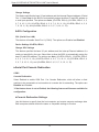
Manual Revision 1.0b
Release Date: June 07, 2019
Unless you request and receive written permission from Super Micro Computer, Inc., you may not copy any part of this
document. Information in this document is subject to change without notice. Other products and companies referred
to herein are trademarks or registered trademarks of their respective companies or mark holders.
Copyright © 2019 by Super Micro Computer, Inc.
All rights reserved.
Printed in the United States of America
WARNING: This product can expose you to chemicals including
lead, known to the State of California to cause cancer and birth
defects or other reproductive harm. For more information, go
to www.P65Warnings.ca.gov.
!

3
Preface
Preface
About This Manual
This manual is written for system integrators, IT technicians and knowledgeable end users. It
provides information for the installation and use of the M11SDV-4C/4CT/8C/8CT/8C+-LN4F
motherboard.
About This Motherboard
The Supermicro M11SDV-4C/4CT/8C/8CT/8C+-LN4F motherboard supports an AMD EPYC™
3000 SoC series processor with up to 8 cores and 16 threads per socket. The AMD EPYC™
3000 upholds optimized performance with NVMe storage, offering up to 512GB of memory,
with speeds of up to 2666MHz. It offers an Intelligent Platform Management Interface (IPMI)
feature, IPMI out-of-band, and a power usage effectiveness mode that provides management
and monitoring capabilities, as well as a M.2 solid-state drive. This is a high performance,
low powered mini-ITX motherboard that is ideal for super compact servers requiring high
compute power. Please note that this motherboard is intended to be installed and serviced
by professional technicians only. For processor/memory updates, please refer to our website
at http://www.supermicro.com/products/.
Manual Organization
Chapter 1 describes the features, specications and performance of the motherboard, and
provides detailed information on the AMD® EPYC 3000 SoC.
Chapter 2 provides hardware installation instructions. Read this chapter when installing the
processor, memory modules, and other hardware components into the system.
If you encounter any problems, see Chapter 3, which describes troubleshooting procedures
for video, memory, and system setup stored in the CMOS.
Chapter 4 includes an introduction to the BIOS, and provides detailed information on running
the BIOS Setup utility.
Appendix A provides BIOS Error Beep Codes.
Appendix B lists software program installation instructions.
Appendix C lists standardized warning statements in various languages.
Appendix D provides UEFI BIOS Recovery instructions.

4
Contacting Supermicro
Headquarters
Address: Super Micro Computer, Inc.
980 Rock Ave.
San Jose, CA 95131 U.S.A.
Tel: +1 (408) 503-8000
Fax: +1 (408) 503-8008
[email protected] (Technical Support)
Website: www.supermicro.com
Europe
Address: Super Micro Computer B.V.
Het Sterrenbeeld 28, 5215 ML
's-Hertogenbosch, The Netherlands
Tel: +31 (0) 73-6400390
Fax: +31 (0) 73-6416525
[email protected] (Technical Support)
[email protected] (Customer Support)
Website: www.supermicro.nl
Asia-Pacic
Address: Super Micro Computer, Inc.
3F, No. 150, Jian 1st Rd.
Zhonghe Dist., New Taipei City 235
Taiwan (R.O.C)
Tel: +886-(2) 8226-3990
Fax: +886-(2) 8226-3992
Website: www.supermicro.com.tw
Super M11SDV-4C/4CT/8C/8CT/8C+-LN4F User's Manual

5
Table of Contents
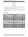
Chapter 1 Introduction
1.1 Checklist ...............................................................................................................................8
Quick Reference ...............................................................................................................13
Quick Reference Table ......................................................................................................15
Motherboard Features .......................................................................................................16
1.2 Processor Overview ...........................................................................................................19
1.3 Special Features ................................................................................................................19
Recovery from AC Power Loss .........................................................................................19
1.4 System Health Monitoring ..................................................................................................20
Onboard Voltage Monitors ................................................................................................20
Fan Status Monitor with Firmware Control .......................................................................20
Environmental Temperature Control .................................................................................20
System Resource Alert......................................................................................................20
1.5 ACPI Features ....................................................................................................................21
1.6 Power Supply .....................................................................................................................21
Chapter 2 Installation
2.1 Static-Sensitive Devices .....................................................................................................22
Precautions .......................................................................................................................22
Unpacking .........................................................................................................................22
2.2 Motherboard Installation .....................................................................................................23
Tools Needed ....................................................................................................................23
Location of Mounting Holes ..............................................................................................23
Installing the Motherboard.................................................................................................24
2.3 Memory Support and Population ........................................................................................25
Memory Support ................................................................................................................25
DIMM Module Population Conguration ...........................................................................26
DIMM Module Population Sequence ................................................................................27
DIMM Installation ..............................................................................................................28
DIMM Removal .................................................................................................................28
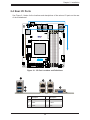
2.4 Rear I/O Ports ....................................................................................................................29
2.5 Front Control Panel ............................................................................................................33
Preface

6
2.6 Connectors and Headers ...................................................................................................38
Power Connections ...........................................................................................................38
Headers ..............................................................................................................................39
2.7 Jumper Settings .................................................................................................................46
How Jumpers Work ...........................................................................................................46
2.8 LED Indicators ....................................................................................................................52
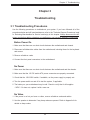
Chapter 3 Troubleshooting
3.1 Troubleshooting Procedures ..............................................................................................55
Before Power On ..............................................................................................................55
No Power ..........................................................................................................................55
No Video ...........................................................................................................................55
System Boot Failure ..........................................................................................................56
Memory Errors ..................................................................................................................56
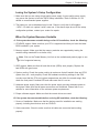
Losing the System's Setup Conguration .........................................................................57
When the System Becomes Unstable ..............................................................................57
3.2 Technical Support Procedures ...........................................................................................59
3.3 Frequently Asked Questions ..............................................................................................60
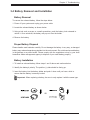
3.4 Battery Removal and Installation .......................................................................................61
Battery Removal ................................................................................................................61
Proper Battery Disposal ....................................................................................................61
Battery Installation .............................................................................................................61
3.5 Returning Merchandise for Service ....................................................................................62
Chapter 4 UEFI BIOS
4.1 Introduction .........................................................................................................................63
Starting the Setup Utility ...................................................................................................63
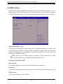
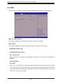
4.2 Main Setup .........................................................................................................................64
4.3 Advanced ............................................................................................................................66
4.4 IPMI ....................................................................................................................................84
4.5 Event Logs .........................................................................................................................88
4.6 Security ...............................................................................................................................90
4.7 Boot ....................................................................................................................................94
4.8 Save & Exit .........................................................................................................................96
Super M11SDV-4C/4CT/8C/8CT/8C+-LN4F User's Manual

7
Appendix A BIOS Codes
Appendix B Software Installation
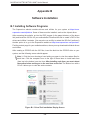
B.1 Installing Software Programs ...........................................................................................100
B.2 SuperDoctor® 5 ................................................................................................................101
Appendix C Standardized Warning Statements
Battery Handling ..............................................................................................................102
Product Disposal .............................................................................................................104
Appendix D UEFI BIOS Recovery

8
Super M11SDV-4C/4CT/8C/8CT/8C+-LN4F User's Manual
Main Parts List (included in the retail box)
Description Part Number Quantity
Supermicro Motherboard M11SDV-4C/4CT/8C/8CT/8C+-LN4F 1
Quick Reference Guide MNL-2172-QRG 1
SATA Data Cables CBL-0044L 4
SATA Power Cable CBL-PWEX-0982 1
24-pin ATX to 4-pin Power Cable CBL-PWEX-1063 1
I/O Shield MCP-260-00084-0N 1
Chapter 1
Introduction
Congratulations on purchasing your computer motherboard from an acknowledged leader in
the industry. Supermicro boards are designed with the utmost attention to detail to provide
you with the highest standards in quality and performance.
Please check that the following items have all been included with your motherboard. If
anything listed here is damaged or missing, contact your retailer. The following items are
included in the retail box:
1.1 Checklist
Main Parts List (included in the Bulk box)
Description Part Number Quantity
Supermicro Motherboard M11SDV-4C/4CT/8C/8CT/8C+-LN4F 1
SATA Data Cables CBL-0044L 2
SATA Power Cable CBL-PWEX-0982 1
24-pin ATX to 4-pin Power Cable CBL-PWEX-1063 1
I/O Shield MCP-260-00084-0N 1

9
Chapter 1: Introduction
Important Links
For your system to work properly, please follow the links below to download all necessary
drivers/utilities and the user’s manual for your server.
• Supermicro product manuals: http://www.supermicro.com/support/manuals/
• Product drivers and utilities: https://www.supermicro.com/wftp/driver/
• Product safety info: http://www.supermicro.com/about/policies/safety_information.cfm
• If you have any questions, please contact our support team at: [email protected]m
This manual may be periodically updated without notice. Please check the Supermicro website
for possible updates to the manual revision level.

10
Super M11SDV-4C/4CT/8C/8CT/8C+-LN4F User's Manual
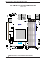
Figure 1-1. M11SDV-4C/4CT/8C/8CT-LN4F Motherboard Image

11
Chapter 1: Introduction
Figure 1-2. M11SDV-8C+-LN4F Motherboard Image

12
Super M11SDV-4C/4CT/8C/8CT/8C+-LN4F User's Manual
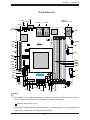
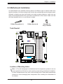
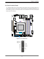
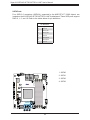
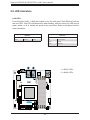
Figure 1-3. M11SDV-4C/4CT/8C/8CT/8C+-LN4F Motherboard Layout
(not drawn to scale)
Note: Components not documented are for internal testing only.
BAR CODE
BMC
AST2500
J1
SGPIO1
JBM1
JBM2
JD1
JPV1
J6
PJ1
JF1
LED3
FAN2
FAN1
FANA
M2_SRW1
JBT1
JWD1
JPG1
JVR1
JVRM1
JVRM2
JI2C1
JI2C2
JHDT1
JTPM1
JSTBY1
JSMB
SATA2
SATA1
SATA0
BT1
JPI2C1
DIMMB2
DIMMA2
DIMMB1
DIMMA1
LED2
LEDM1
LED1
COM1
JMD2
JPCIE1
SATA3
JGP1
M11SDV-4CT-LN4F
REV:1.02
DESIGNED IN USA
i350
1
CPU SLOT7 PCI-E 3.0 X16
SATA POWER
VGA
PCI-E 3.0 X4 M.2-HC
USB 6/7(3.0)
USB 4/5
USB 2/3
USB 0/1
CPU
IPMI_LAN
LAN 1/2
LAN 3/4
VGA
ON
PWR
JF1
RST
UID
X
OH/FF
2
NIC
1
LED
NIC HDD
LED
X
PWR
NMI
1-2:ENABLE
2-3:DISABLE
JPG1:
2-3:NMI
1-2:RST
JWD1:WATCH DOG
4-7:SPEAKER
1-3:PWR LEDJD1:
1-2:ENABLE
2-3:DISABLE
JI2C1/JI2C2:
UID
SUPER DOM

13
Chapter 1: Introduction
BAR CODE
BMC
AST2500
J1
SGPIO1
JBM1
JBM2
JD1
JPV1
J6
PJ1
JF1
LED3
FAN2
FAN1
FANA
M2_SRW1
JBT1
JWD1
JPG1
JVR1
JVRM1
JVRM2
JI2C1
JI2C2
JHDT1
JTPM1
JSTBY1
JSMB
SATA 2
SATA 1
SATA 0
BT1
JPI2C1
DIMMB2
DIMMA2
DIMMB1
DIMMA1
LED2
LEDM1
LED1
COM1
JMD2
JPCIE1
SATA 3
JGP1
M11SDV-4CT-LN4F
REV:1.02
DESIGNED IN USA
i350
1
CPU SLOT7 PCI-E 3.0 X16
SATA POWER
VGA
PCI-E 3.0 X4 M.2-HC
USB 6/7(3.0)
USB 4/5
USB 2/3
USB 0/1
CPU
IPMI_LAN
LAN 1/2
LAN 3/4
VGA
ON
PWR
JF1
RST
UID
X
OH/FF
2
NIC
1
LED
NIC HDD
LED
X
PWR
NMI
1-2:ENABLE
2-3:DISABLE
JPG1:
2-3:NMI
1-2:RST
JWD1:WATCH DOG
4-7:SPEAKER
1-3:PWR LEDJD1:
1-2:ENABLE
2-3:DISABLE
JI2C1/JI2C2:
UID
SUPER DOM
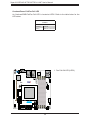
Notes:
• See Chapter 2 for detailed information on jumpers, I/O ports, and JF1 front panel connec-
tions. Jumpers/LED indicators not indicated are used for testing only.
• " " indicates the location of Pin 1.
• When LED3 (Onboard Power LED indicator) is on, system power is on. Unplug the power
cable before installing or removing any components.
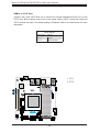
Quick Reference
IPMI_LAN
USB6/7 (3.1 Gen 1)
FAN1
DIMMB1
DIMMB2
USB4/5
LAN1/2
JPV1
DIMMA1
DIMMA2
JSTBY1
JD1
JPI2C1
JBM1
JI2C1
UID
LED2
PJ1
JSMB
LAN3/4
LED1
SATA2
LED3
SGPIO1
COM1
JHDT1
JMD2
JPG1
JF1
USB2/3
JVRM1
JVRM2
JGP1
USB0/1
SATA1
SATA0
SATA3
J6
FAN2
BT1
JBT1
VGA
JPCIE1
LEDM1
FANA
M2_SRW1
JTPM1
JVR1
JWD1
JBM2
JI2C2

14
Super M11SDV-4C/4CT/8C/8CT/8C+-LN4F User's Manual
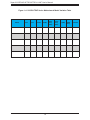
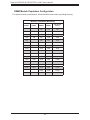
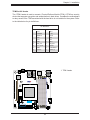
Figure 1-4. X11SDV-TP8F Series Motherboard Model Variation Table
Model CPU Core Threads TDP(W)
Base
Freq
(GHz)
Boost
Freq
(GHz)
L3 (MB)
DDR
Freq
Heatsink
M11SDV-8C+-LN4F 3251 8 16 55 2.5 3.1 16 2666 active
M11SDV-8C-LN4F 3251 8 16 55 2.5 3.1 16 2666 passive
M11SDV-8CT-LN4F 3201 8 8 30 1.5 3.1 16 2133 passive
M11SDV-4C-LN4F 3151 4 8 45 2.7 2.9 16 2666 passive
M11SDV-4CT-LN4F 3101 4 4 35 2.1 2.0 8 2666 passive

15
Chapter 1: Introduction
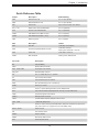
Quick Reference Table
Jumper Description Default Setting
JBM1 Disable Share LAN Pin 1-2 Open (Enable)
JBM2 Disable IPMI/Share LAN Pin 1-2 Open (Enable)
JBT1 CMOS Clear Open: Normal, Closed: Clear CMOS
JI
2
C1, JI
2
C2 SMB to PCI-E Slots Enable/Disable Pins 2-3 (Disabled)
JPG1 Onboard VGA Enable/Disable Pins 1-2 (Enabled)
JVRM1 VRM SMB Clock (to BMC or PCH) Pins 1-2 (Normal)
JVRM2 VRM SMB Data (to BMC or PCH) Pins 1-2 (Normal)
JWD1 Watch Dog Timer Pins 1-2 (Reset)
LED Description Status
LED1 UID LED Solid Blue: Unit Identied
LED2 Overheat (OH)/PWR Fail/Fan Fail LED
Solid Red: Overheat
Blinking Red: PWR Fail or Fan Fail
LED3 Power LED Solid Green: Power On
LEDM1 BMC Heartbeat Blinking Green: BMC Normal
Connector Description
BT1 Onboard Battery
COM1 RS232 COM Port Header
FAN1 - FAN2, FANA CPU/System Fan Headers
IPMI_LAN Dedicated IPMI LAN Port
JD1 Pins 1-2: PWR LED, Pin 4-7: Speaker
JF1 Front Control Panel Header
JGP1 8-bit General Purpose I/O Header
JMD2 M.2 Slot 2280 M-key (PCIe x 4/SATA 3.0)
JPCIE1 PCI-E 3.0 x 16 Slot
JPI
2
C1 Power I
2
C System Management Bus (Power SMB) Header
JPV1 8-pin 12V DC Power Input (Required for 12V only or 24-pin ATX power)
JSMB System Management Bus Header
JSTBY1 Standby Power Connector
JTPM1 Trusted Platform Module (TPM)/Port 80 Connector
LAN1 - LAN4 1 GbE LAN (RJ45) Ports
PJ1 Header for ATX Power Signal 5VSTBY/Power ON/Power Good/Ground; 24pin ATX to
4pin power cable for PJ1 (Supermicro P/N: CBL-PWEX-1063)
SATA0 - SATA3 SATA 3.0 Ports
UID Unit Identier Switch
USB0-5 USB 2.0 Header
USB6/7 Back Panel USB 3.0 Ports
VGA VGA Port (back panel)

16
Super M11SDV-4C/4CT/8C/8CT/8C+-LN4F User's Manual
Note: The table above is continued on the next page.
Motherboard Features
CPU
• Supports an AMD EPYC™ 3000 SoC processor
Memory
• Supports DDR4 ECC/Non-ECC RDIMM, UDIMM, and LRDIMM memory in 4 DIMM slots, up to 512GB, with speed of up
to 2666MHz.
Note: When the motherboard is populated with 4 modules of 2S4R/4DR DDR4 LRDIMM, the memory will operate
at speed of 2133MHz.
When the motherboard is fully populated with 4 modules of single rank DDR4 RDIMM, the memory will operate at
speed of 2133MHz.
When the motherboard is fully populated with 4 modules of 2R/2DR/2S2R/2S4R DDR4 RDIMM, the memory will
operate at speed of 1866MHz.
When the motherboard is fully populated with 4 modules of single rank DDR4 UDIMM, the memory will operate at
speed of 2133MHz.
When the motherboard is fully populated with 4 modules of 2R/2DR DDR4 UDIMM, the memory will operate at
speed of 1866MHz.
DIMM Size
• 4GB, 8GB, 16GB, 32GB, 64GB, and 128GB
Expansion Slots
• One (1) PCI-E 3.0 x 16 slot
Network Controller
• ASpeed AST2500 and Intel i350
Baseboard Management Controller (BMC)
• ASpeed AST2500
Graphics
• Graphics controller via ASpeed AST2500
I/O Devices
• Com Header • One (1) RS232 COM Port Header
• SATA 3.0 • Four (4) SATA 3.0 ports
Peripheral Devices
• Six (6) USB 2.0 ports in three (3) internal headers (USB0/1, USB2/3, USB4/5)
• Two (2) USB 3.0 ports on the I/O back panel (USB6/7)
Motherboard Features

17
Chapter 1: Introduction
Motherboard Features
BIOS
• 128Mb AMI BIOS® SPI Flash BIOS
• UEFI 2.6, ACPI 6.1, PCI FAV 3.0, SMBIOS 3.1, SPI dual/quad speed support, Real Time Clock (RTC) wakeup
Power Management
• ACPI power management
• Wake-On-LAN (JWOL)
• S5
• Power button override mechanism
• Power-on mode for AC power recovery
System Health Monitoring
• Onboard voltage monitors for Vcore, Vmem, Vsocrun, Vsocdual, +3.3V, +5V, +12V, +3.3V Stby, +5V Stby, VBAT, CPU
Temperature, System Temperature, Memory Temperature, Peripheral Temperature, and VRM Temperature
• CPU/System overheat control
• CPU Thermal Trip support
Fan Control
• Fan status monitoring with rmware
• Three (3) 4-pin fan headers with speed control
System Management
• IPMIVIEW, SMCIPMITOOL, IPMICFG
• System management via SuperDoctor® 5, Watch Dog
• Power supply monitoring
• SUM-INBand, SUM-OOB
LED Indicators
• CPU/system overheat LED
• Fan failed LED
• LAN activity LED
• UID LED
• Power LED
Other
• RoHS
Dimensions
• Mini-ITX form factor (6.75" x 6.75") (170 mm x 170 mm)
Note 1: For IPMI conguration instructions, please refer to the Embedded IPMI Con-
guration User's Guide available at http://www.supermicro.com/support/manuals/.
Note 2: If you purchase a Supermicro Out of Band (OOB) software license key
(Supermicro P/N: SFT-OOB--LIC), please DO NOT change the IPMI MAC address.

18
Super M11SDV-4C/4CT/8C/8CT/8C+-LN4F User's Manual
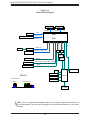
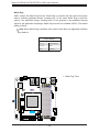
Note: This is a general block diagram and may not exactly represent the features on
your motherboard. See the previous pages for the actual specications of your moth-
erboard.
Figure 1-5.
Chipset Block Diagram
Rear USB 3.0 x 2
CPU1
USB3.0
5Gbps
Header USB 2.0 x 2
USB2.0
500Mbps
FLASH
SPI 128Mb
SPI
TPM1.2 Header
AST2500
SVID
3 Phase VR
MEM_DIMMA
AMD
MEM_DIMMC
SVI2
Slot 1 PCIe x16 ( or 2 x 8 )
BGA
PCIe3.0_x16
8.0GT/s
SATA-III
6Gb/s
PCIe3.0_x4
8.0GT/s
I350 PCIe x4
PCIe3.0_x4 / SATA x 1
8.0GT/s or 6Gb/s
M.2_M PCIe x4
HUB
HUB
Header
USB2 x2
PCIe x 1
COM1 (Header)
Health Info.
RJ45
VGA (KVM)
LPC
4 X SATA-III
USB2 x2
Header
VGA
USB3.0
Dedicated LAN
+
RJ45 x4
Group B 0~15
Group A 12~15
Group A 4~7
Group A 0~3
USB_1_SS_0 & USB_1_HSD0
USB_1_SS_1 & USB_1_HSD1
USB_0_HSD1
USB_0_HSD0
MEM_DIMMDMEM_DIMMB
REAR IO
2666MHz2666MHz
1G LAN1G LAN

19
Chapter 1: Introduction
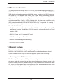
1.2 Processor Overview
The Supermicro M11SDV-4C/4CT/8C/8CT/8C+-LN4F motherboard supports an AMD EPYC™
3000 SoC series processor with up to 8 cores and 16 threads per socket. The AMD EPYC™
3000 upholds optimized performance with NVMe storage, offering up to 512GB of memory,
with speed of up to 2666MHz and 50W of power, while offering performance, reliability,
and high intelligence. It offers an Intelligent Platform Management Interface (IPMI) feature,
IPMI out-of-band, and a power usage effectiveness mode that provides management and
monitoring capabilities, as well as a M.2 solid-state drive. As a low-power system-on-a-chip
(SoC) motherboard, the M11SDV-4C/4CT/8C/8CT/8C+-LN4F is optimized for a variety of
workloads that requires high compute power in a compact form-factor.
The AMD EPYC™ 3000 supports the following features:
• Zen Microarchitecture, 14nm, System on Chip, RAS, Secure Memory Encryption (SME),
and Secure Encrypted Virtualization (SEV) for securely isolating hypervisors and virtual
machines VMS
• 16MB L3 Cache, up to 8 Core and 16 Thread
• ACPI Power Management Rev. 6.1
• Adaptive Thermal Management/Monitoring
• PCI-E 3.0, SATA 3.0, NVMe
1.3 Special Features
This section describes the health monitoring features of the
M11SDV-4C/4CT/8C/8CT/8C+-LN4F motherboard. The motherboard has an onboard
System Hardware Monitor chip AST2500 that supports system health monitoring.
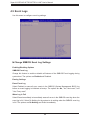
Recovery from AC Power Loss
The Basic Input/Ouput System (BIOS) provides a setting that determines how the system
will respond when AC power is lost and then restored to the system. You can choose for the
system to remain powered off (in which case you must press the power switch to turn it back
on), or for it to automatically return to the power-on state. See the Advanced BIOS Setup
section for this setting. The default setting is Last State.

20
Super M11SDV-4C/4CT/8C/8CT/8C+-LN4F User's Manual
Environmental Temperature Control
System health sensors monitor temperatures and voltage settings of onboard processors
and the system in real time via the IPMI interface. Whenever the temperature of the CPU or
the system exceeds a user-dened threshold, system/CPU cooling fans will be turned on to
prevent the CPU or the system from overheating.
Note: To avoid possible system overheating, please provide adequate airow to your
system.
System Resource Alert
This feature is available when used with SuperDoctor 5® in the Windows OS or in the Linux
environment. SuperDoctor is used to notify the user of certain system events. For example,
you can congure SuperDoctor to provide you with warnings when the system temperature,
CPU temperatures, voltages and fan speeds go beyond a predened range.
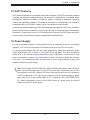
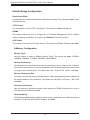
1.4 System Health Monitoring
This section describes the health monitoring features of the M11SDV-4C/4CT/8C/8CT/8C+-LN4F
motherboard. The motherboard has an onboard Baseboard Management Controller (BMC)
chip that supports system health monitoring.
Onboard Voltage Monitors
The onboard voltage monitor will continuously scan crucial voltage levels. Once a voltage
becomes unstable, it will give a warning or send an error message to the screen. Users can
adjust the voltage thresholds to dene the sensitivity of the voltage monitor. Real time readings
of these voltage levels are all displayed in BIOS.
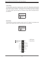
Fan Status Monitor with Firmware Control
The system health monitor chip can check the RPM status of a cooling fan. The CPU and
chassis fans are controlled by BIOS Thermal Management through the back panel. Refer
to the below table for available fan modes to choose the most appropriate one for nominal
operation.
Fan Mode Description
Full Speed Use this mode to set fan speed at full speed for maximum system cooling
Standard Use this mode to set fan speed for normal system cooling
Heavy I/O Use this mode to set fan speed for higher PCI-E add-on card area cooling
Optimal Use this mode to set fan speed for normal PCI-E add-on card area cooling
PUE2 Use this mode to set fan speed for best power efciency and maximum noise reduction
Page is loading ...
Page is loading ...
Page is loading ...
Page is loading ...
Page is loading ...
Page is loading ...
Page is loading ...
Page is loading ...
Page is loading ...
Page is loading ...
Page is loading ...
Page is loading ...
Page is loading ...
Page is loading ...
Page is loading ...
Page is loading ...
Page is loading ...
Page is loading ...
Page is loading ...
Page is loading ...
Page is loading ...
Page is loading ...
Page is loading ...
Page is loading ...
Page is loading ...
Page is loading ...
Page is loading ...
Page is loading ...
Page is loading ...
Page is loading ...
Page is loading ...
Page is loading ...
Page is loading ...
Page is loading ...
Page is loading ...
Page is loading ...
Page is loading ...
Page is loading ...
Page is loading ...
Page is loading ...
Page is loading ...
Page is loading ...
Page is loading ...
Page is loading ...
Page is loading ...
Page is loading ...
Page is loading ...
Page is loading ...
Page is loading ...
Page is loading ...
Page is loading ...
Page is loading ...
Page is loading ...
Page is loading ...
Page is loading ...
Page is loading ...
Page is loading ...
Page is loading ...
Page is loading ...
Page is loading ...
Page is loading ...
Page is loading ...
Page is loading ...
Page is loading ...
Page is loading ...
Page is loading ...
Page is loading ...
Page is loading ...
Page is loading ...
Page is loading ...
Page is loading ...
Page is loading ...
Page is loading ...
Page is loading ...
Page is loading ...
Page is loading ...
Page is loading ...
Page is loading ...
Page is loading ...
Page is loading ...
Page is loading ...
Page is loading ...
Page is loading ...
Page is loading ...
Page is loading ...
Page is loading ...
Page is loading ...
Page is loading ...
Page is loading ...
Page is loading ...
-
 1
1
-
 2
2
-
 3
3
-
 4
4
-
 5
5
-
 6
6
-
 7
7
-
 8
8
-
 9
9
-
 10
10
-
 11
11
-
 12
12
-
 13
13
-
 14
14
-
 15
15
-
 16
16
-
 17
17
-
 18
18
-
 19
19
-
 20
20
-
 21
21
-
 22
22
-
 23
23
-
 24
24
-
 25
25
-
 26
26
-
 27
27
-
 28
28
-
 29
29
-
 30
30
-
 31
31
-
 32
32
-
 33
33
-
 34
34
-
 35
35
-
 36
36
-
 37
37
-
 38
38
-
 39
39
-
 40
40
-
 41
41
-
 42
42
-
 43
43
-
 44
44
-
 45
45
-
 46
46
-
 47
47
-
 48
48
-
 49
49
-
 50
50
-
 51
51
-
 52
52
-
 53
53
-
 54
54
-
 55
55
-
 56
56
-
 57
57
-
 58
58
-
 59
59
-
 60
60
-
 61
61
-
 62
62
-
 63
63
-
 64
64
-
 65
65
-
 66
66
-
 67
67
-
 68
68
-
 69
69
-
 70
70
-
 71
71
-
 72
72
-
 73
73
-
 74
74
-
 75
75
-
 76
76
-
 77
77
-
 78
78
-
 79
79
-
 80
80
-
 81
81
-
 82
82
-
 83
83
-
 84
84
-
 85
85
-
 86
86
-
 87
87
-
 88
88
-
 89
89
-
 90
90
-
 91
91
-
 92
92
-
 93
93
-
 94
94
-
 95
95
-
 96
96
-
 97
97
-
 98
98
-
 99
99
-
 100
100
-
 101
101
-
 102
102
-
 103
103
-
 104
104
-
 105
105
-
 106
106
-
 107
107
-
 108
108
-
 109
109
-
 110
110


Supermicro M11SDV-4C-LN4F User manual
- Category
- Server/workstation motherboards
- Type
- User manual
- This manual is also suitable for
Ask a question and I''ll find the answer in the document
Finding information in a document is now easier with AI
Related papers
-
Supermicro A+ Server AS-E301-9D-8CN4 User manual
-
Supermicro Supero C7Z97-M User manual
-
-
-
-
-
-
-
-
Other documents
-
 Supero C7B360-CB-M User manual
-
Biostar X470NH User manual
-
DFI SO630 Owner's manual
-
Dell PowerEdge 7250 Owner's manual
-
-
Vdwall SC-12 User manual
-
-
 Hypertec ORION HD525U-G5C-24T4N Owner's manual
-
Shenzhen B W Electronics Development BT022 Wireless Mini Numeric Keypad User manual
-
Gigabyte G492-ZD2 User manual

