Page is loading ...

Smart-UPS
®
VT
10-30 kVA
208/220 V
Site Preparation and
Installation Manual


Smart-UPS® VT 10-30kVA, 208V, Site Preparation and Installation – 990-1598A 1
Smart-UPS
®
VT 10-30 kVA 208/220 V
Site Preparation and Installation Manual
IMPORTANT SAFETY INSTRUCTIONS –
SAVE THESE INSTRUCTIONS
This manual contains important instructions for the SUVT series that should be
followed during installation and maintenance of the UPS and Batteries


Contents
990-1598B Smart-UPS® VT 10-30 kVA, 208/220 V Site Preparation and Installation Manual i
Safety .....................................................................1
General Safety Instructions . . . . . . . . . . . . . . . . . . . . . . . . . . . . 1
Symbols used in this guide . . . . . . . . . . . . . . . . . . . . . . . . . . . . 1
Environmental symbols . . . . . . . . . . . . . . . . . . . . . . . . . . . . . . . 1
General safety . . . . . . . . . . . . . . . . . . . . . . . . . . . . . . . . . . . . . . 2
Introduction ............................................................3
UPS Family Range and Components . . . . . . . . . . . . . . . . . . . . . 4
13.85 in/352 mm Enclosures . . . . . . . . . . . . . . . . . . . . . . . . . . . 4
20.59 in/523 mm Enclosures . . . . . . . . . . . . . . . . . . . . . . . . . . . 4
Serial number . . . . . . . . . . . . . . . . . . . . . . . . . . . . . . . . . . . . . . 5
Type label . . . . . . . . . . . . . . . . . . . . . . . . . . . . . . . . . . . . . . . . . 5
User interface . . . . . . . . . . . . . . . . . . . . . . . . . . . . . . . . . . . . . . 6
Connection Interface (rear) . . . . . . . . . . . . . . . . . . . . . . . . . . . . 7
Foot print . . . . . . . . . . . . . . . . . . . . . . . . . . . . . . . . . . . . . . . . . 8
APC Network Management Card AP9619 (installed in UPS)
and APC Humidity Sensor (Optional) . . . . . . . . . . . . . . . . . . . . . 9
Site Preparation .....................................................10
Installation Space Requirements . . . . . . . . . . . . . . . . . . . . . . . 10
Clearance for 20.59 in/523 mm Enclosures . . . . . . . . . . . . . . . 10
Clearance for stand-alone 13.85 in/352 mm Enclosures . . . . . . 11
Operating Environment . . . . . . . . . . . . . . . . . . . . . . . . . . . . . 12
Operating conditions . . . . . . . . . . . . . . . . . . . . . . . . . . . . . . . 12
Heat dissipation . . . . . . . . . . . . . . . . . . . . . . . . . . . . . . . . . . . 12
Audible noise . . . . . . . . . . . . . . . . . . . . . . . . . . . . . . . . . . . . . 12
Recommended current protection . . . . . . . . . . . . . . . . . . . . . . 13
Minimum breaker settings for 10 kVA UPS . . . . . . . . . . . . . . . . 13
Minimum breaker settings for 15 kVA UPS . . . . . . . . . . . . . . . . 14
Minimum breaker settings for 20 kVA UPS . . . . . . . . . . . . . . . . 14
Minimum setting of breakers for 30 kVA UPS . . . . . . . . . . . . . . 14
Recommended phase-conductor sizes [AWG] for a 86°F
(30°C) temperature environment . . . . . . . . . . . . . . . . . . . . . . . 15
EPO switch wiring . . . . . . . . . . . . . . . . . . . . . . . . . . . . . . . . . . 15

ii Smart-UPS® VT 10-30 kVA, 208/220 V Site Preparation and Installation Manual 990-1598B
Basic Wiring Overview . . . . . . . . . . . . . . . . . . . . . . . . . . . . . . 16
Site Preparation Checklist . . . . . . . . . . . . . . . . . . . . . . . . . . . . 17
Mechanical assembly ............................................ 18
Stabilizing Brackets . . . . . . . . . . . . . . . . . . . . . . . . . . . . . . . . . 18
Leveling Feet . . . . . . . . . . . . . . . . . . . . . . . . . . . . . . . . . . . . . 19
Floor Anchoring . . . . . . . . . . . . . . . . . . . . . . . . . . . . . . . . . . . 20
Drilling floor holes for floor anchoring . . . . . . . . . . . . . . . . . . . 20
Hole positions for floor anchors (stand-alone Enclosures) . . . . . 20
Floor anchoring of stand-alone systems . . . . . . . . . . . . . . . . . . 21
Electrical Installation ............................................ 22
System-Electrical Information . . . . . . . . . . . . . . . . . . . . . . . . . 22
Source connections . . . . . . . . . . . . . . . . . . . . . . . . . . . . . . . . . 24
One-line diagram for Smart-UPS VT 10, 15, 20, 30kVA,
208V, 3 phase, single mains . . . . . . . . . . . . . . . . . . . . . . . . . . 25
One-line diagram for Smart-UPS VT 10, 15, 20, 30kVA,
220V, 3 phase, single mains . . . . . . . . . . . . . . . . . . . . . . . . . . 26
Wiring . . . . . . . . . . . . . . . . . . . . . . . . . . . . . . . . . . . . . . . . . . 27
Input/Output Wiring – Single Mains (default) . . . . . . . . . . . . . 28
Input/Output Wiring – Dual Mains . . . . . . . . . . . . . . . . . . . . . 30
External Battery Wiring . . . . . . . . . . . . . . . . . . . . . . . . . . . . . 32
Wiring to battery bank or battery racks . . . . . . . . . . . . . . . . . . 32
Communication Wiring to EPO and Optional Equipment . . . . 33
Pin connections J106 (XR Enclosure) and J108 (EPO) . . . . . . . . 34
Pin connections J106 (UPS) to J200 (XR Enclosure - option) . . . 34
XR Enclosure, APC Maintenance Bypass Panel, and Generator
Control wiring . . . . . . . . . . . . . . . . . . . . . . . . . . . . . . . . . . . . . 35
Pin connections J108 (for EPO wiring options) . . . . . . . . . . . . 36
Connection of APC Humidity Sensor . . . . . . . . . . . . . . . . . . . . 37
Front panel removal . . . . . . . . . . . . . . . . . . . . . . . . . . . . . . . . 37
Wiring Verification Procedure . . . . . . . . . . . . . . . . . . . . . . . . . 40
Installation Site Checklist . . . . . . . . . . . . . . . . . . . . . . . . . . . . 41

990-1598B Smart-UPS® VT 10-30 kVA, 208/220 V Site Preparation and Installation Manual 1
Safety
General Safety Instructions
This guide contains important instructions that should be followed when handling the UPS, Battery
Enclosures, and batteries.
Symbols used in this guide
Environmental symbols
WARNING!
Risk of electric shock.
CAUTION!
Read this information to avoid equipment damage.
Note
Indicates important information.
Indicates that more information is available on this subject in a different section of this
manual.
Indicates that more information is available on the same subject in a different manual.
Temperature Ventilation
requirements
Humidity Dust/Fumes Altitude

Safety – General Safety Instructions
2 Smart-UPS® VT 10-30 kVA, 208/220 V Site Preparation and Installation Manual 990-1598B
General safety
WARNING!
All electrical power and control wiring must be installed by a qualified electrician and
comply with local and national codes.
WARNING!
When connected, the UPS contains energy from both AC and DC sources. If the UPS
has dual mains supply, be aware of the two AC supply sources. Risk of electric shock -
parts inside the UPS are energized from the battery supply even the AC power is
disconnected.
WARNING!
Servicing of batteries should be performed or supervised by personnel knowledgeable
of batteries and the required precautions. Keep unauthorized personnel away from
batteries.
WARNING!
Batteries do not contain serviceable parts. Only APC authorized personnel may open
batteries.
WARNING!
Do not dispose of battery or batteries in a fire. The battery may explode. Do not open or
mutilate the battery or batteries. Released electrolyte is harmful to the skin and eyes. It
may be toxic.
WARNING!
Risk of Energy Hazard, 96 V, 7.2 Ampere-hour battery. Before replacing batteries,
remove watches, rings, or other metal objects. High energy through conductive
materials could cause severe burns.
WARNING!
When handling batteries, wear rubber gloves and boots. Do not lay tools or metal
objects on top of batteries.
WARNING!
When replacing a Battery Unit, replace with the same number of the APC SYBT1
(always replace a whole Battery Module (4 Battery Units) at a time).
WARNING!
Only trained personnel familiar with the construction and operation of the equipment
and the electrical and mechanical hazards involved, may install and remove system
components.
For configurations including customer-supplied external batteries, refer to
manufacturer’s battery installation and maintenance instructions.

990-1598B Smart-UPS® VT 10-30 kVA, 208/220 V Site Preparation and Installation Manual 3
Introduction
Welcome to the Site Preparation and Installation Manual for the Smart-UPS
®
VT. This manual
contains information on how to prepare your site for the installation of the UPS and optional APC
equipment (also available at www.apc.com) and instructions on how to carry out the electrical/
mechanical installation. Separate manuals are available on:
• Receiving and Unpacking - part no. 990-1747
• Operation - part no. 990-1599
Note
Keep the UPS free from loose objects to prevent obstruction of the airflow.
Note
For more information on APC products and services, visit us at www.apc.com
Note
Most illustrations show 20.59 in / 523 mm Enclosures but apply to both Enclosure sizes
(13.85 in / 352 mm and 20.59 in / 523 mm). Any differences between the two Enclosure
sizes will be addressed in the manual.

4 Smart-UPS® VT 10-30 kVA, 208/220 V Site Preparation and Installation Manual 990-1598B
UPS Family Range and Components
13.85 in/352 mm Enclosures
20.59 in/523 mm Enclosures
8
8
5-2321C_rev04
Unit
S
eria
l
N
o
Voltage
&
Connection Types
A
PC SKU
SUVT10KF1
B
2S
SUVT10KF2B2S
SUVT10K
F1
B4S
SUVT10K
F2
B4S
SUVT10KF
3
B4S
SU
V
T10KF4B
4S
SUVT1
5K
F
2
B2S
S
U
VT1
5K
F2B4S
SUVT1
5KF3B
4S
S
U
VT15KF4B4S
SUVT20
KF2B4
S
SUVT20K
F3
B4S
SUVT2
0
KF4B4S
S
UV
T3
0
KF3B4
S
SUVT30KF4B4S
Worldwide Support
n
um
ber
s
:
w
ww
.
a
pcc
.
c
o
m/sup
p
ort
/
servi
c
e/geomap_w
o
rl
d
.dfm
Ho
t
l
i
ne
i
n U
S/Ca
na
d
a
/
L
A
M
:
+1 800
800
4APC
Hotli
n
e
i
n
E
ME
A
:
+35
3
91 7
0
2
000
Ra
t
ed Input Current
27.1A
208V
4
0
.
6
A
2
0
8V
54
.2A
2
08
V
81.3A
208V
Ra
t
ed
Outp
ut
Cur
r
ent
27.8
A
2
0
8
V
41
.
6A
208
V
5
5.5A
208V
83
.
3A
20
8V
Bat
te
r
y
C
ur
r
e
nt
28.
9A
43
.
3
A
57.7A
86.6A
SUVTF10KB2F
SUVT
F1
0K
B
4
F
S
U
VTF15
KB2
F
SUVTF15
K
B4F
SUVTF20KB4F
S
UVTF3
0
KB4F
A
ppa
r
ent
/
Active
Powe
r
10kVA/8kW
1
5
kVA/
1
2k
W
2
0k
VA/
1
6
kW
3
0k
VA/24k
W
AC Output
208Y/120V 4W+GND
6
0
Hz
A
C
Input
208Y/120V 4W+GND 60Hz
DC Input
+/- 192
V
Model
APC Smart-UPS VT 10kVA 20
8
V
w/
1
B
at
t.
M
od
u
l
e
Ex
p.
to
2
APC Smar
t
-
UPS
VT
1
0k
V
A 208V
w/
2 Batt
.
Mod
ule
s
APC Sma
r
t-UPS VT 10
k
VA 2
0
8V
w
/
1 Batt
.
Modu
l
e Exp.
t
o 4
APC
Sm
a
r
t
-UPS
V
T 1
0kV
A
2
08V
w/2 Batt. Modules Exp. to 4
A
P
C Smart-UPS VT 10kVA 208V
w
/3 Batt
.
Mo
d
ul
e
s E
x
p. to
4
A
P
C Sm
ar
t
-
U
PS
VT
1
0k
V
A 208V
w
/
4 Batt
.
Mo
d
ules
A
P
C
Smart-UPS
VT
1
5kVA
208V
w/
2 Batt
.
M
o
du
l
e
s
APC Smart
-
UPS VT 15kVA 208V
w/
2
B
at
t
.
M
odu
les E
x
p
. t
o
4
A
P
C Smart-UPS VT 15kVA 208V
w
/3 Batt. Mo
du
les E
x
p. to
4
APC Smar
t
-UPS VT 15k
V
A 20
8V
w
/4
Batt. M
o
dules
APC Smart-UPS VT 20kVA 208V
w
/2
Ba
t
t
. Mod
u
l
e
s
Exp
.
t
o
4
APC Smart
-
UPS
V
T 20kVA 208V
w/
3
B
att. M
o
du
l
e
s
Ex
p
. t
o
4
APC
S
ma
r
t
-
UP
S
VT 20kVA 208V
w/
4
Ba
t
t. Modu
l
es
APC S
m
art
-
UPS
V
T 30kVA 208V
w/3 Batt. Modu
l
es
Exp. to 4
APC
Sm
a
rt-UPS VT
3
0
kV
A 2
0
8V
w
/
4 Batt. Mo
d
ules
Date
i
n
stall
e
d
Da
t
e for
1
.
Re
p
lac
em
e
nt
Dat
e
fo
r
2.
Replacement
Batte
r
y Capacit
y
@–
192V
DC
7
.2Ah
14
.
4
A
h
7
.
2A
h
14
.
4
Ah
2
1.6Ah
2
8.
8
Ah
1
4
.4Ah
14.4Ah
2
1.6Ah
28.8Ah
1
4
.
4
Ah
2
1.6Ah
28.
8
Ah
21
.
6
A
h
28.8Ah
SEE INSTALLATION INSTRUCTION
S
BEFORE CONNEC
T
I
N
G TO
T
HE
SUPPLY
Ba
tt
e
r
i
es
TH
IS
R
E
AR
CO
V
E
R
M
US
T
BE
P
LA
CED
O
N UPS
10/100B
as
e
-
T
Pr
o
be
AP
9
619 Network
Ma
nage
me
nt Card
EM
!
Reset
O
ut
pu
t
P
w
r
Zo
ne
10
/
100
Model:
Serial:
BATTERY UNIT
Mode
l
:
Serial:
BATTERY UNIT
Mo
d
el:
Serial:
BATTERY UNIT
Model:
Serial:
BATTERY UNIT
M
o
del
:
Serial:
BATTERY UNIT
M
o
de
l
:
S
e
rial
:
BATTERY UNIT
Mode
l:
Seri
al
:
BATTER
Y
UNIT
Mode
l:
S
eria
l:
BATTERY U
NI
T
Front Rear Front without front panel
10-15 kVA
885-2321C_rev04
Unit Serial No
Voltage & Connection Types
APC SKU
SUVT10KF1B2S
SUVT10KF2B2S
SUVT10KF1B4S
SUVT10KF2B4S
SUVT10KF3B4S
SUVT10KF4B4S
SUVT15KF2B2S
SUVT15KF2B4S
SUVT15KF3B4S
SUVT15KF4B4S
SUVT20KF2B4S
SUVT20KF3B4S
SUVT20KF4B4S
SUVT30KF3B4S
SUVT30KF4B4S
Worldwide Support numbers: www.apcc.com/support/service/geomap_world.dfm
Hotline in US/Canada/LAM: +1 800 800 4APC
Hotline in EMEA: +353 91 70 2000
Rated Input Current
27.1A
208V
40.6A
208V
54.2A
208V
81.3A
208V
Rated Output Current
27.8A
208V
41.6A
208V
55.5A
208V
83.3A
208V
Battery Current
28.9A
43.3A
57.7A
86.6A
SUVTF10KB2F
SUVTF10KB4F
SUVTF15KB2F
SUVTF15KB4F
SUVTF20KB4F
SUVTF30KB4F
Apparent/
Active Power
10kVA/8kW
15kVA/12kW
20kVA/16kW
30kVA/24kW
AC Output
208Y/120V 4W+GND 60Hz
AC Input
208Y/120V 4W+GND 60Hz
DC Input
+/- 192V
Model
APC Smart-UPS VT 10kVA 208V
w/1 Batt. Module Exp. to 2
APC Smart-UPS VT 10kVA 208V
w/2 Batt. Modules
APC Smart-UPS VT 10kVA 208V
w/1 Batt. Module Exp. to 4
APC Smart-UPS VT 10kVA 208V
w/2 Batt. Modules Exp. to 4
APC Smart-UPS VT 10kVA 208V
w/3 Batt. Modules Exp. to 4
APC Smart-UPS VT 10kVA 208V
w/4 Batt. Modules
APC Smart-UPS VT 15kVA 208V
w/2 Batt. Modules
APC Smart-UPS VT 15kVA 208V
w/2 Batt. Modules Exp. to 4
APC Smart-UPS VT 15kVA 208V
w/3 Batt. Modules Exp. to 4
APC Smart-UPS VT 15kVA 208V
w/4 Batt. Modules
APC Smart-UPS VT 20kVA 208V
w/2 Batt. Modules Exp. to 4
APC Smart-UPS VT 20kVA 208V
w/3 Batt. Modules Exp. to 4
APC Smart-UPS VT 20kVA 208V
w/4 Batt. Modules
APC Smart-UPS VT 30kVA 208V
w/3 Batt. Modules Exp. to 4
APC Smart-UPS VT 30kVA 208V
w/4 Batt. Modules
Date
installed
Date for 1.
Replacement
Date for 2.
Replacement
Battery Capacity
@– 192V DC
7.2Ah
14.4Ah
7.2Ah
14.4Ah
21.6Ah
28.8Ah
14.4Ah
14.4Ah
21.6Ah
28.8Ah
14.4Ah
21.6Ah
28.8Ah
21.6Ah
28.8Ah
SEE INSTALLATION INSTRUCTIONS
BEFORE CONNECTING TO THE
SUPPLY
Batteries
THIS REAR COVER MUST BE
PLACED ON UPS
10/1
0
0
Bas
e
-T
P
r
obe
AP9619 Netw
o
rk Manag
e
me
n
t Ca
r
d
EM
!
R
es
e
t
Output
P
wr
Zone
10/100
Model:
Serial:
BATTERY UNIT
Model:
Serial:
BATTERY UNIT
Model:
Serial:
BATTERY UNIT
Model:
Serial:
BATTERY UNIT
Model:
Serial:
BATTERY UNIT
Model:
Serial:
BATTERY UNIT
Model:
Serial:
BATTERY UNIT
Mode
l
:
Serial:
BATTERY UNIT
10/100Base-T
P
r
obe
AP9619 Network
M
a
nage
m
e
n
t
C
ar
d
E
M
!
Re
s
et
Output
Pwr
Zone
1
0
/10
0
Model:
Serial:
BATTERY UNIT
Model:
Serial:
BATTERY UNIT
Model:
Serial:
BATTERY UNIT
Model:
Serial:
BATTERY UNIT
Model:
Serial:
BATTERY UNIT
Model:
Serial:
BATTERY UNIT
Model:
Serial:
BATTERY UNIT
Model:
Serial:
BATTERY UNIT
Model:
Serial:
BATTERY UNIT
Model:
Serial:
BATTERY UNIT
Model:
Serial:
BATTERY UNIT
Model:
Serial:
BATTERY UNIT
Model:
Serial:
BATTERY UNIT
Model:
Serial:
BATTERY UNIT
Model:
Serial:
BATTERY UNIT
Model:
Serial:
BATTERY UNIT
Front
Rear
Front without
front panel 10-15 kVA
Front without
front panel 20-30 kVA
Blind plates
cover
empty
battery bays

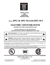
Introduction – UPS Family Range and Components
990-1598B Smart-UPS® VT 10-30 kVA, 208/220 V Site Preparation and Installation Manual 5
Serial number
The serial number is available on the type label on the rear side of the UPS.
Type label
885-2321D_rev05
Unit Serial No
Voltage & Connection Types
APC SKU
SUVT10KF1B2S
SUVT10KF2B2S
SUVT10KF1B4S
SUVT10KF2B4S
SUVT10KF3B4S
SUVT10KF4B4S
SUVT15KF2B2S
SUVT15KF2B4S
SUVT15KF3B4S
SUVT15KF4B4S
SUVT20KF2B4S
SUVT20KF3B4S
SUVT20KF4B4S
SUVT30KF3B4S
SUVT30KF4B4S
Worldwide Support numbers: www.apcc.com/support/service/geomap_world.dfm
Hotline in US/Canada/LAM: +1 800 800 4APC
Hotline in EMEA: +353 91 70 2000
Rated Input Current
27.1/25.5A
208/220V
40.6/38.4A
208/220V
54.2/51.2A
208/220V
81.3/76.7A
208/220V
Rated Output Current
27.8/26.2A
208/220V
41.6/39.4A
208/220V
55.5/52.5A
208/220V
83.3/78.7A
208/220V
Battery Current
28.9A
43.3A
57.7A
86.6A
SUVTF10KB2F
SUVTF10KB4F
SUVTF15KB2F
SUVTF15KB4F
SUVTF20KB4F
SUVTF30KB4F
Apparent/
Active Power
10kVA/8kW
15kVA/12kW
20kVA/16kW
30kVA/24kW
AC Output
208Y/120V 4W+GND 60Hz
220Y/127V 4W+GND 60Hz
AC Input
208Y/120V 4W+GND 60Hz
220Y/127V 4W+GND 60Hz
DC Input
± 192V
Model
APC Smart-UPS VT 10kVA 208/220V
w/1 Batt. Module Exp. to 2
APC Smart-UPS VT 10kVA 208/220V
w/2 Batt. Modules
APC Smart-UPS VT 10kVA 208/220V
w/1 Batt. Module Exp. to 4
APC Smart-UPS VT 10kVA 208/220V
w/2 Batt. Modules Exp. to 4
APC Smart-UPS VT 10kVA 208/220V
w/3 Batt. Modules Exp. to 4
APC Smart-UPS VT 10kVA 208/220V
w/4 Batt. Modules
APC Smart-UPS VT 15kVA 208/220V
w/2 Batt. Modules
APC Smart-UPS VT 15kVA 208/220V
w/2 Batt. Modules Exp. to 4
APC Smart-UPS VT 15kVA 208/220V
w/3 Batt. Modules Exp. to 4
APC Smart-UPS VT 15kVA 208/220V
w/4 Batt. Modules
APC Smart-UPS VT 20kVA 208/220V
w/2 Batt. Modules Exp. to 4
APC Smart-UPS VT 20kVA 208/220V
w/3 Batt. Modules Exp. to 4
APC Smart-UPS VT 20kVA 208/220V
w/4 Batt. Modules
APC Smart-UPS VT 30kVA 208/220V
w/3 Batt. Modules Exp. to 4
APC Smart-UPS VT 30kVA 208/220V
w/4 Batt. Modules
Date
installed
Date for 1.
Replacement
Date for 2.
Replacement
Battery Capacity
@± 192V DC
7.2Ah
14.4Ah
7.2Ah
14.4Ah
21.6Ah
28.8Ah
14.4Ah
14.4Ah
21.6Ah
28.8Ah
14.4Ah
21.6Ah
28.8Ah
21.6Ah
28.8Ah
SEE INSTALLATION INSTRUCTIONS
BEFORE CONNECTING TO THE
SUPPLY
Batteries
THIS REAR COVER MUST BE
PLACED ON UPS

Introduction – UPS Family Range and Components
6 Smart-UPS® VT 10-30 kVA, 208/220 V Site Preparation and Installation Manual 990-1598B
User interface
Display: user-control interface used to configure the functionality, monitor the system, set alarm
thresholds, and to provide audible and visual alarms.
Network Management Card with Environmental Monitor (AP9619): used for remote system
control and monitoring, e-mail notifications etc.
Computer-interface port for the connection of computers with APC Powerchute
®
software.
Mechanical Bypass Lever: used to bypass the upstream mains power around the UPS to support
the load directly = internal mechanical bypass operation.
Service port (for APC maintenance personnel only).
10/100Base-T
Probe
AP9619 Network Manag
ement Card EM
!
Reset
Output
Pwr
Zone
10/100
Model:
Serial:
BATTERY UNIT
Model:
Serial:
BATTERY UNIT
Model:
Serial:
BATTERY UNIT
Model:
Serial:
BATTERY UNIT
Model:
Serial:
BATTERY UNIT
Model:
Serial:
BATTERY UNIT
Model:
Serial:
BATTERY UNIT
Model:
Serial:
BATTERY UNIT
Model:
Serial:
BATTERY UNIT
Model:
Serial:
BATTERY UNIT
Model:
Serial:
BATTERY UNIT
Model:
Serial:
BATTERY UNIT
Model:
Serial:
BATTERY UNIT
Model:
Serial:
BATTERY UNIT
Model:
Serial:
BATTERY UNIT
Model:
Serial:
BATTERY UNIT

Introduction – UPS Family Range and Components
990-1598B Smart-UPS® VT 10-30 kVA, 208/220 V Site Preparation and Installation Manual 7
Display port for the connection of display communication cable.
Documentation storage.
Inlet for communication cables.
Connection Interface (rear)
Upper Cover Plate rear.
Upper part of Conduit Box.

Introduction – UPS Family Range and Components
8 Smart-UPS® VT 10-30 kVA, 208/220 V Site Preparation and Installation Manual 990-1598B
Lower part of Conduit Box.
Power connection.
Communication wiring connection (EPO signalling, Battery Temperature Sensor).
Protective earth.
Foot print
Conduit Box.
Levelling feet.
Castors.
Communication cable inlets.
Rear Rear
20.59 in/523 mm
13.85 in/352 mm
36.45 in/
926 mm

Introduction – UPS Family Range and Components
990-1598B Smart-UPS® VT 10-30 kVA, 208/220 V Site Preparation and Installation Manual 9
APC Network Management Card AP9619 (installed in UPS) and APC Humidity Sensor
(Optional)
For installing Humidity Sensor see “Connection of APC Humidity Sensor” on page 40.
10/100Base-T
Probe
AP9619 Network Management Card EM
!
Reset
Output
Pwr
Zone
10/100
Humidity Sensor

10 Smart-UPS® VT 10-30 kVA, 208/220 V Site Preparation and Installation Manual 990-1598B
Site Preparation
Installation Space Requirements
Clearance for 20.59 in/523 mm Enclosures
*) Minimum free rear space for ventilation 4 in/100 mm.
Space requirements in mm
Minimum clearance above Enclosure (A) 20.00 508
Enclosure depth (B) 32.99 838
Enclosure width (C) 20.59 523
Minimum rear service clearance* (compliant with NEC 110.26 for
North America) (D)
36.00 914
Minimum front clearance (E) 40.00 1,000
Conduit Box, depth (F) 3.46 88
No side clearance required (add width of Stabilizing Brackets for
floor anchoring if applicable)
00
Stabilizing Bracket width 3.34 85
Total installation depth, inclusive of Front Panel, Conduit Box and
minimum front and rear clearances (G)
112.45 2,840
(E)
(D)
(A)
UPS
Conduit Box
(F)
(B)
(G)
(C)

Site Preparation – Installation Space Requirements
990-1598B Smart-UPS® VT 10-30 kVA, 208/220 V Site Preparation and Installation Manual 11
Clearance for stand-alone 13.85 in/352 mm Enclosures
*) Minimum free rear space for ventilation 4 in/100 mm.
Space requirements in mm
Minimum clearance above UPS (A) 20.00 508
UPS depth (B) 32.99 854
UPS width 13.85 352
Minimum rear service clearance* (compliant with NEC 110.26
for North America) (D)
36.00 914
Minimum front clearance (E) 40.00 1,000
Conduit Box, depth (F) 3.46 88
No side clearance required (add width of Stabilizing Bracket for
floor anchoring if applicable)
00
Stabilizing Bracket width 3.34 85
Total installation depth, inclusive of Front Panel, Conduit Box
and minimum front and rear clearances (G)
112.45 2.840
For the stability of 13.85 in/352 mm stand-alone Enclosures, the Stabilizing Brackets
must always be mounted on both sides of the UPS. See Stabilizing Brackets.
(C)
(A)
(D)
Stabilizing Bracket,
left and right
UPS
Conduit Box (F)
(B)
(G)
(E)

12 Smart-UPS® VT 10-30 kVA, 208/220 V Site Preparation and Installation Manual 990-1598B
Operating Environment
Operating conditions
Heat dissipation
Audible noise
Note
Install the UPS in an indoor, temperature-controlled area, free of conductive
contaminants.
Temperature
Range:
32° to 104°F /
0° to 40°C
Keep Ventilated
Front-to-Rear
Airflow (see
space
considerations)
Relative
Humidity: <95%
Non-condensing
No Conductive
Dust or
Corrosive
Fumes
Altitude derating table:
3,000 ft/914 m: 100% load
4,500 ft/1371 m: 95% load
6,000 ft/1828 m: 91% load
8,000 ft/2438 m: 86% load
10,000 ft/3048 m: 82% load
UPS size
BTU/hr at fully
charged batteries UPS size
BTU/hr at fully
charged batteries
10 kVA 1,774 20 kVA 3,624
15 kVA 2,866 30 kVA 5,486
UPS Sizes
Audible noise at 100% load
(1.09 yard/1 m from the UPS)
Audible noise at <70% load
(1.09 yard/1 m from the UPS)
10-15 kVA 54 dBA 45.4 dBA
20-30 kVA 58 dBA 48.5 dBA

Site Preparation – Operating Environment
990-1598B Smart-UPS® VT 10-30 kVA, 208/220 V Site Preparation and Installation Manual 13
Recommended current protection
Note 1: If the available fault current of the installation is below 30 kA, a lower kAIC-rated breaker can be
used.
Note 2: For breaker settings, refer to below table listing available overload currents.
Note 3: If the available fault current of the installation is less than 1200 A for the 10 kVA and 15 kVA UPS
sizes, and below 2300 A for the 20 kVA and 30 kVA UPS sizes, a breaker (of the same value as for the
bypass input) can be used.
Note 4: Recommended maximum rating of a single-fuse configuration if the internal bypass is to be protected
during a load short-circuit.
Minimum breaker settings for 10 kVA UPS
Note 1: For the output value, the short-circuit-level is indicated.
Note
AC output over-current protection and AC output disconnect must be provided by the
customer.
Dual/single
mains
configuration Connection 10 kVA 15 kVA 20 kVA 30 kVA Notes
Single Mains/bypass
input
35 A
breaker (30
kAIC)
60 A
breaker (30
kAIC)
80 A breaker
(30 kAIC)
125 A breaker
(30 kAIC)
Dual Mains input 35 A
breaker
(30 kAIC)
60 A
breaker
(30 kAIC)
80 A breaker
(30 kAIC)
125 A breaker
(30 kAIC)
1, 2
Dual Bypass input 35 A
breaker
(30 kAIC)
60 A
breaker
(30 kAIC)
80 A breaker
(30 kAIC)
125 A breaker
(30 kAIC)
1, 2
Any Output 35 A fast-
acting class
J fuse
60 A fast-
acting class
J fuse
80 A fast-
acting class
J fuse
125 A fast-
acting class
J fuse
3, 4
Overload Event Mains input Bypass input Output Duration Notes
Internal fault 2 kA 1.7 kA 14 kA <10 ms 1
800% overload bypass
operation
– 223 A 223 A 500 ms
150% overload normal/
battery operation
– – 42 A 30 s
125% overload normal/
battery operation
– – 35 A 60 s
Continuously 34 A 31 A 31 A
∞

Site Preparation – Operating Environment
14 Smart-UPS® VT 10-30 kVA, 208/220 V Site Preparation and Installation Manual 990-1598B
Minimum breaker settings for 15 kVA UPS
Note 1: For the output value, the short-circuit-level is indicated
Minimum breaker settings for 20 kVA UPS
Note 1: For the output value, the short-circuit-level is indicated.
Minimum setting of breakers for 30 kVA UPS
Note 1: For the output value, the short-circuit level is indicated.
Overload Event Mains input Bypass input Output Duration Notes
Internal fault 2.5 kA 2.1 kA 14 kA <10 ms 1
800% overload bypass
operation
– 333 A 333 A 500 ms
150% overload normal/
battery operation
– – 63 A 30 s
125% overload normal/
battery operation
– – 52 A 60 s
Continuously 51 A 46 A 46 A
∞
Overload Event Mains input Bypass input Output Duration Notes
Internal fault 4 kA 3.4 kA 14 kA <10 ms 1
800% overload bypass
operation
– 444 A 444 A 500 ms
150% overload normal/
battery operation
– – 84 A 30 s
125% overload normal/
battery operation
– – 70 A 60 s
Continuously 68 A 62 A 62 A
∞
Overload Event Mains input Bypass input Output Duration Notes
Internal fault 5 kA 4.2 kA 14 kA <10 ms 1
800% overload bypass
operation
– 667 A 667 A 500 ms
150% overload normal/battery
operation
– – 125 A 30 s
125% overload normal/battery
operation
– – 105 A 60 s
Continuously 102 A 92 A 92 A
∞
/